
ZGARD S & DS
Gas Sensors
Instruction Manual
THIS MANUAL MUST BE CAREFULLY READ BY ALL INDIVIDUALS WHO HAVE OR WILL HAVE
THE RESPONSIBILITY FOR USING OR SERVICING THE PRODUCT. Like any piece of complex
equipment, this instrument will perform as designed only if it is used and serviced in accordance
with the manufacturer’s instructions. OTHERWISE, IT COULD FAIL TO PERFORM AS DESIGNED
AND PERSONS WHO RELY ON THIS PRODUCT FOR THEIR SAFETY COULD SUSTAIN SEVERE
PERSONAL INJURY OR DEATH.
The warranties made by Mine Safety Appliances Company with respect to the product are voided
if the product is not used and serviced in accordance with the instructions in this manual. Please
protect yourself and others by following them. We encourage our customers to write or call
regarding this equipment prior to use or for any additional information relative to use or service.
Manuel d’instructions
Veuillez lire attentivement les instructions qui suivent. Tous ceux qui sont responsables, ou qui
aurons la responsabilité pour l’installation, la fonctionnalité ou l’usage de ce produit doivent se
familiariser complètement avec ses instructions. Comme tout appareil complexifié, ce produit
peut vous donner les résultats anticipés seulement s’il est installé, usagé et que le service d’en-
tretien sont effectués d’après les instructions du fabricant (ou manufacturier). Sous peine de ne
pas suivre les instructions ci-incluses, il est possible que cet appareil vous donne des résultats
insuffisant. En conséquence, les personnes qui dépendront sur ce produit pour leur sécurité peu-
vent être blessés ou mourir.
Les garanties de ‘Mine Safety Appliances Company’ par rapport à ces produits sont annulés si les
produits ne sont pas installés, usagés et le service maintenus conformément aux instructions ci-
incluses. Veuillez vous protéger ainsi que les autres, en suivant les instructions d’installations.
S’il vous plaît, entrez en communications avec nous au sujet de ce produit avant l’utilisation de
ce produit ou pour plus amples renseignements, sois pour l’usage ou les réparations.
In North America., to contact your nearest stocking location, dial toll-free 1-800-MSA-INST
To contact MSA International, dial (724) 776-8626
© MINE SAFETY APPLIANCES COMPANY 2014 - All Rights Reserved
This manual is available on the internet at www.MSAsafety.com
Manufactured by
MSA NORTH AMERICA
1000 Cranberry Woods Drive, Cranberry Township, PA 16066
(L) Rev 2 10063481
"! WARNING
"! Détecteur d’Émanations

MSA Permanent Instrument Warranty
1 Warranty - Seller warrants that this product will be free from mechanical defect or faulty
workmanship for a period of eighteen (18) months from date of shipment or one (1) year
from installation, whichever occurs first, provided it is maintained and used in accordance
with Seller's instructions and / or recommendations. This warranty does not apply to
expendable or consumable parts whose normal life expectancy is less than one (1) year
such as, but not limited to, non-rechargeable batteries, filament units, filter, lamps, fuses
etc. The Seller shall be released from all obligations under this warranty in the event
repairs or modifications are made by persons other than its own or authorized service
personnel or if the warranty claim results from physical abuse or misuse of the product.
No agent, employee or representative of the Seller has any authority to bind the Seller to
any affirmation, representation or warranty concerning the product. Seller makes no
warranty concerning components or accessories not manufactured by the Seller, but will
pass on to the Purchaser all warranties of manufacturers of such components. THIS
WARRANTY IS ON LIEU OF ALL OTHER WARRANTIES, EXPRESSED, IMPLIED OR
STATUTORY, AND IS STRICTLY LIMITED TO THE TERMS HEREOF. SELLER
SPECIFICALLY DISCLAIMS ANY WARRANTY OF MERCHANTABILITY OR OF
FITNESS FOR A PARTICULAR PURPOSE.
2. Exclusive Remedy - It is expressly agreed that Purchaser's sole and exclusive remedy
for breach of the above warranty, for any tortious conduct of Seller, or for any other cause
of action, shall be the repair and / or replacement at Seller's option, of any equipment or
parts thereof, which after examination by Seller is proven to be defective. Replacement
equipment and /or parts will be provided at no cost to Purchaser, F.O.B. Seller's Plant.
Failure of Seller to successfully repair any nonconforming product shall not cause the
remedy established hereby to fail of its essential purpose.
3. Exclusion of Consequential Damage - Purchaser specifically understands and agrees
that under no circumstances will Seller be liable to Purchaser for economic, special,
incidental or consequential damages or losses of any kind whatsoever, including but not
limited to, loss of anticipated profits and any other loss caused by reason of nonoperation
of the goods. This exclusion is applicable to claims for breach of warranty, tortious
conduct or any other cause of action against seller.
ii

iii
1. The ZGARD S & DS gas sensors described
in this manual must be installed, operated,
and maintained in strict accordance with the
labels, cautions, warnings, instructions, and
within the limitations stated.
2. The ZGARD S & DS gas sensors must not
be installed in outdoor areas or in locations
where explosive concentrations of
combustible gases or vapors might occur in
the atmosphere: Class 1, Group A, B, C, and
D areas as defined by the NEC. Because the
gas sensors are not explosion-proof, they
must be located in non-hazardous areas. The
ZGARD S & DS gas sensor must not
be subject to direct sunlight or equivalent.
3. Do not paint the ZGARD S & DS gas
sensors. Cleaning must be with warm water
only (no cleaning solutions).
4. The only absolute method to assure the
proper overall operation of a gas detection
instrument is to check it with a known
concentration of the gas for which it has been
calibrated. Consequently, a calibration check
must be included as part of the installation
and as a routine inspection of the system.
5. Use only genuine MSA replacement parts
when performing any maintenance
procedures provided in this manual.
Failure to do so may seriously impair
instrument performance. Repair or alteration
of the ZGARD S & DS gas sensors, beyond
the scope of these maintenance instructions
or by anyone other than authorized MSA
service personnel, could cause the product to
fail to perform as designed, and persons who
rely on this product for their safety could
sustain serious personal injury or death.
6. The ZGARD S & DS gas sensors must be
installed, located and operated in accordance
to all applicable codes. These codes include,
but are not limited to, the National Fire
Prevention Code and National Electric Code.
7. Do not exceed the relay contact ratings listed
in this manual. Otherwise, the relay operation
may fail, which can result in personal injury
or death.
FAILURE TO COMPLY WITH THE
ABOVE WARNINGS CAN RESULT
ON SERIOUS PERSONAL INJURY
OR DEATH.
1. Le détecteur d’émanations ZGARD S & DS
tel que représenté dans ce manuel doit être
installé, opéré et maintenu conformément aux
étiquettes, les cautions, avertissements, ainsi
que les instructions et les restrictions
spécifiées.
2. Le détecteur d’émanations ZGARD S & DS
ne doit pas être fixé en plein air ou dans une
région où des concentrations explosives de
gaz ou de vapeur sont présentes dans
l’atmosphère; Classe 1, Groupes A, B, C, et
D comme définis pas le NEC. Étant donné
que les détecteurs d’émanations ne sont pas
protégés contre les explosions, ils devraient
être localisé dans un endroit non-dangereux.
Le détecteur d’émanation ZGARD S & DS ne
doit pas être exposé au soleil.
3. Veuillez ne pas peinturer le ZGARD S & DS .
Nettoyer uniquement avec de l’eau tiède,
sans savon ou produits de nettoyage.
4. Pour vérifier que l’appareil fonctionne bien, il
s’agit de l’exposer à une concentration
d’émanation pour laquelle l’appareil a été
calibré. Conséquemment, une vérification du
calibre doit être incluse comme partie de
l’installation ainsi qu’à l’inspection régulière
du système.
5. Un mot de caution lors de l’entretien de cet
appareil; il est nécessaire d’utiliser que les
pièces MSA lors d’effectuer l’entretien de cet
appareil. Sinon, l’appareil peut faillir. Toutes
réparations ou modifications du détecteur
d’émanations au dessus des instructions ci-
incluses, ou par autre personne non-autorisée
par le MSA peut causer une faillite mettant en
danger les personnes qui dépendent sur cet
appareil pour leur bien-être contre les
blessures et la mortalité.
6. Le détecteur d’émanations ZGARD S & DS
doit être fixé, localisé, et opéré conformément
aux codes applicable. Ces codes sont inclus,
mais pas limités au ‘National Fire Prevention
Code’ et le ‘National Electric Code.’
7. Ne pas dépasser l’indique du relais tel que
spécifié dans ce manuel d’instructions.
Autrement, l’opération du relais peut faire
faillite qui, par la suite peut causer des
blessures physiques ou même la mortalité.
CAUTION: Si vous n’adhéré pas aux
avertissements ci-haut spécif
"
WARNING
"
AVERTISSEMENTS
General Warnings

iv
Table of Contents
Chapter 1,
General Information and Applications . . . . . . . . . . . . . . . . . . . . . . . .1-1
Table 1-1. ZGARD S & DS Sensors . . . . . . . . . . . . . . . . . . . . . . . . . . . . . . . . . .1-1
Chapter 2,
Installation Guidelines . . . . . . . . . . . . . . . . . . . . . . . . . . . . . . . . . . . . .2-1
Mounting . . . . . . . . . . . . . . . . . . . . . . . . . . . . . . . . . . . . . . . . . . . . . . . . . . . . . . . . . . .2-1
Wiring Connections . . . . . . . . . . . . . . . . . . . . . . . . . . . . . . . . . . . . . . . . . . . . . . . . . . .2-1
" WARNING . . . . . . . . . . . . . . . . . . . . . . . . . . . . . . . . . . . . . . . . . . . . . . . . . . . .2-1
" CAUTION . . . . . . . . . . . . . . . . . . . . . . . . . . . . . . . . . . . . . . . . . . . . . . . . . . . . .2-1
Chapter 3,
Start-Up . . . . . . . . . . . . . . . . . . . . . . . . . . . . . . . . . . . . . . . . . . . . . . . . .3-1
Operating Features and Setup ZGARD S Sensors (4 to 20 mA and RS-485) . . . . . .3-1
Table 3-1. ZGARD S & DS Sensor Specifications . . . . . . . . . . . . . . . . . . . . . . . .3-1
ZGARD S Sensors (RS-485 Only) . . . . . . . . . . . . . . . . . . . . . . . . . . . . . . . . . . . . . . . .3-2
Bump Test . . . . . . . . . . . . . . . . . . . . . . . . . . . . . . . . . . . . . . . . . . . . . . . . . . . . . . . . .3-2
Table 3-2. Digital Binary Address Codes . . . . . . . . . . . . . . . . . . . . . . . . . . . . . . .3-3
Chapter 4,
Calibration . . . . . . . . . . . . . . . . . . . . . . . . . . . . . . . . . . . . . . . . . . . . . . .4-1
Calibration Procedure . . . . . . . . . . . . . . . . . . . . . . . . . . . . . . . . . . . . . . . . . . . . . . . . .4-1
" WARNING . . . . . . . . . . . . . . . . . . . . . . . . . . . . . . . . . . . . . . . . . . . . . . . . . . . .4-1
Calibration Equipment . . . . . . . . . . . . . . . . . . . . . . . . . . . . . . . . . . . . . . . . . . . . . . . . .4-1
" WARNING . . . . . . . . . . . . . . . . . . . . . . . . . . . . . . . . . . . . . . . . . . . . . . . . . . . .4-1
Calibration Of ZGARD S & DS Sensors . . . . . . . . . . . . . . . . . . . . . . . . . . . . . . . . .4-1
Zero Calibration . . . . . . . . . . . . . . . . . . . . . . . . . . . . . . . . . . . . . . . . . . . . . . . . . . . . .4-1
Span Calibration . . . . . . . . . . . . . . . . . . . . . . . . . . . . . . . . . . . . . . . . . . . . . . . . . . . .4-1
Sensor Out of Range or Inoperative After Calibration . . . . . . . . . . . . . . . . . . . . . . . .4-2
Sensor Fail Indication . . . . . . . . . . . . . . . . . . . . . . . . . . . . . . . . . . . . . . . . . . . . . . . .4-2
Chapter 5,
Parts List . . . . . . . . . . . . . . . . . . . . . . . . . . . . . . . . . . . . . . . . . . . . . . . .5-1
Table 5-1. Parts List . . . . . . . . . . . . . . . . . . . . . . . . . . . . . . . . . . . . . . . . . . . . . . .5-1
" WARNING . . . . . . . . . . . . . . . . . . . . . . . . . . . . . . . . . . . . . . . . . . . . . . . . . . . .5-1
Appendix A,
Installation Outline Drawings . . . . . . . . . . . . . . . . . . . . . . . . . . . . . . .A-1

The ZGARD S Sensors are designed to detect the
presence of Carbon Monoxide, Nitrogen Dioxide
and Combustibles in air.
The ZGARD DS is a Dual Sensor in one enclosure
designed to detect the presence of Carbon
Monoxide and Nitrogen Dioxide in air. Depending
on the type of sensor used, electrochemical,
solid-state metal oxide or catalytic bead
technology is employed. Each generates a
representative output signal proportional to the
calibrated operating range.
The ZGARD S & DS sensors are available with
two output versions, a 4-20mA analog output or an
addressable RS485 digital signal. The ZGARD S &
DS, RS485 version is specifically designed to
operate with any MSA ZGARD C 485 or CXII
Controller, operating as a system. The ZGARD S
& DS with 4-20mA output can be installed as a
stand-alone sensor typically integrated with
common commercial equipment including PLC,
DCS or Building Environmental Automation
Systems or operate with any ZGARD C Controller.
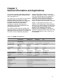
TABLE 1-1 shows distinctive features of the
ZGARD S & DS Sensors and is a quick guide for
determining the operating features of each sensor.
The performance of any ZGARD S & DS Sensor
depends on the appropriate and strategic
placement within a guarded area. Gas sensors
should be strategically placed closest to the areas
where the target gases or vapors might occur in
the atmosphere.
1-1
Chapter 1,
General Information and Applications
Table 1-1. ZGARD S & DS Sensors
CARBON CARBON NITROGEN COMBUSTIBLE
MONOXIDE (SS) MONOXIDE (EC) DIOXIDE (EC) (LEL)
Principal of Operation MOS, Metal Oxide Electrochemical Electrochemical Catalytic Sensor
Semiconductor
Accuracy at STP +/- 10% Full Scale +/- 5% Full Scale +/- 10% Full Scale +/- 5% Full Scale
Operating Range 0-100 ppm 0-100 ppm 0-10 ppm 0-100% LEL
OR OR
0-200 ppm 0-200 ppm
Zero Deadband 17 ppm 1 ppm 0.1 ppm 1% LEL
Output 4-20mA 4-20mA 4-20mA 4-20mA
OR OR OR OR
RS485 Network RS485 Network RS485 Network RS485 Network
Operating Temperature 0° to 40°C -20° to 40°C 0° to 40°C -20° to 40°C
Storage Temperature -10° to 50°C -20° to 50°C -10° to 50°C -20° to 50°C
Humidity 25 to 95% RH 0 to 95% RH 0 to 95% RH 0 to 95% RH
Altitude 0 to 6562 Feet / 0-2000 Meter
SENSOR ENCLOSURE
ZGARD S Enclosure Powder-coated metal double-gang connection box
Dimensions 5.5” H (140 mm) x 5.5" W (140 mm) x 2.2" D (56 mm)
Weight 0.45kg (1.00 lbs.)
ZGARD DS Enclosure Polycarbonate
Dimensions 7.0” H (178 mm) x 10.5" W (267 mm) x 4.5" D (114 mm)
Weight 1.1kg (2.45 lbs.)

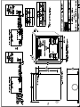
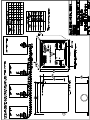
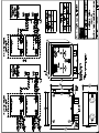
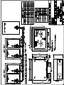
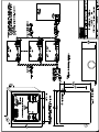
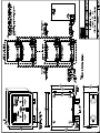
NOTE: Reference the Installation Outline
drawings in this manual, Appendix A.
Mounting
• Do not mount the sensor to structures subject
to vibration and shock, such as piping and
piping supports.
• Do not locate the sensor near an excessive
heat source or in wet or damp locations.
• For proper cooling, allow at least five inches
of clearance around all surfaces except for
the mounting surface. Also consider mounting
the sensor so it can be easily accessed for
service and routine testing.
• The sensor has four mounting lugs; securely
mount the instrument to a wall or support
using appropriate hardware.
Wiring Connections
Before putting a ZGARD S & DS Sensor into
operation, determine the elevation and the number
of gas sensors according to the required
application. Also refer to the ZGARD S & DS
sensor(s) Installation Outline drawings for
important information regarding:
• Operating power
• Required conductors and wire size
• 4-20 mA and RS485 Network wiring
connection.
When wiring the sensor, disconnect
the main power to prevent bodily
harm.
Lors de l’installation électrique du
détecteur, couper le courant d’électric-
ité du détecteur en entier pour éviter
toutes possibilités de chocs qui peut
causer des blessures corporelles.
Do not use the sensor power when
connecting any external devices.
Use shielded cable for wiring installa-
tion. Do not install low voltage signal
cable in the same conduit as the other
devices such as sensors operating
power and or relay wiring.
Make sure that each RS485 sensor is
given a unique address (Switch select-
ed) to enable the MSA ZGARD C series
controller to communicate properly.
When connecting sensors, make sure
all wiring is correct for the power and
signal leads. Ensure the RS485 bus
wiring is not interchanged; otherwise,
permanent sensor damage may result.
Perform all wiring and conduit installa-
tion in accordance with the National
Electrical Code.
Failure to follow the above Warning
and Cautions can result in injury or
property damage.
Utilisez pas le pouvoir électrique du
détecteur pour brancher autres
appareils.
Se servir uniquement le fil conducteur
électrique ayant un écran de protec-
tion. Soyez avisé qu’il faut isoler un
conduit uniquement pour l’électricité
(pouvoir) du détecteur ainsi que le
relais.
Assurez-vous que chaque détecteur a
son propre bouton de contrôle pour
assurer que le contrôleur du MSA
ZGARD S & DS communique directe-
ment tel que branché.
Lorsque vous branchez le détecteur
isolé, assurez-vous que le branchage
de fils électriques sont convenable au
pouvoir (électricité). Veuillez noter que
le fil RS 485 ne doit pas être échangé
pour un autre fil électrique, il est
unique à cet appareil. Autrement, vus
courez le risque d’endommager, en
permanence, le détecteur.
Exécuter tout branchement et installa-
tion de conduit conformément au
“National Electric Code”.
A coup sûr, si les cautions ci-haut
mentionnés ne sont pas suivis, il y a
possibilité de blessures corporelles et
vous courez chance d’endommager
votre propriété.
"
WARNING
"
CAUTION
"
ATTENTION!
"
CAUTION
2-1
Chapter 2,
Installation Guidelines

3-1
Chapter 3,
Start-Up
• The ZGARD S and DS Sensors are factory-calibrated and ready for immediate use.
• Once power is applied to the unit and a 30-second delay occurs, the normal green LED is solid ON
to indicate the sensor is operating properly.
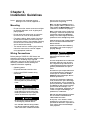
Table 3-1. ZGARD S & DS Sensor Specifications
Operating Power mA 24 VAC/DC 250 mA max Comb
50/60 Hz 100 mA max SS
Class 2 Source 100 mA max EC
RS485 24 VDC 250 mA max Comb
100 mA max SS
Class 2 Source 100 mA max EC
RS485-PR 24 VDC/DC 250 mA max Comb
50/60 Hz 100 mA max SS
Class 2 Source 100 mA max EC
Signal mA Isolated 4-20 mA current source
RS485 2-wire (plus shield) network connection
RS485-PR 2-wire (plus shield) network connection
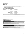
Operating Features and Setup
ZGARD S Sensors
(4 to 20 mA and RS-485)
SW2
àß 1 TEST FULL SCALE (100% OUTPUT)
àß 2 TEST HALF SCALE (50% OUTPUT)
àß 3 TEST ZERO SCALE (0% OUTPUT)
àß 4 CUT-OFF (ON/ OFF)
SW2
àß 1 TEST FULL SCALE (100% OUTPUT)
àß 2 TEST HALF SCALE (50% OUTPUT)
àß 3 TEST ZERO SCALE (0% OUTPUT)
àß 4 CUT-OFF (ON/ OFF)
ZGARD S Sensors, Output Test: Each sensor provides a
means of driving the output to 0%, 50% or 100% full-scale.
Respectively, when the onboard switch SW2 is turned ON to
1 or 2 or 3, the sensor generates the selected output signal.
This feature is useful for testing remote devices, which may be
connected to the sensor output.
ZGARD S Sensors, Zero Deadband: Each sensor provides a
zero deadband (cut-off) option to eliminate possible high
background interference of any unsuspected environmental or
other airborne compounds. This function is switch-enabled.
When SW2, position 4 is in the OFF position, the zero
deadband feature is enabled. When SW2, position 4 is in the
ON position, there is no deadband.

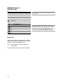
ZGARD S Sensors
(RS-485 Only)
SW2
àß 1 TEST FULL SCALE (100% OUTPUT)
àß 2 TEST HALF SCALE (50% OUTPUT)
àß 3 TEST ZERO SCALE (0% OUTPUT)
àß 4 CUT-OFF (ON/ OFF)
àß 5 NOT USED
àß 6 NOT USED
àß 7 PRIBUSIN
àß 8 NOT USED
SW1 RS-485 ADDRESS 1 - 127
(SET BY BINARY)
1 àß 1
2 àß 2
4 àß 3
8 àß 4
16àß 5
32àß 6
64àß 7
For RS-485 Sensors, SW2 - position 7 must always be turned
ON. This will allow the sensor to communicate to a C 485, CX
or CXII controller.
Digital Address Binary Code Setup: Each sensor must be
given a unique address code for accurate communication. The
binary address code is set by arranging the user selection
switch SW1 as shown. Turning on SW1 switches 1, 2, 3, 4, 5, 6
and 7 according to the appropriate Binary Address Code
required for each application. See TABLE 3-2 for details.
3-2
Bump Test
Apply a representative sample gas to the sensor
and check if the sensor responds to the target gas
and has reached the appropriate value.
NOTE: Any connected remote equipment may
be activated.
The initial sensor function test is now completed.

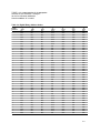
TABLE 3-2 is a representation of the appropriate
selection of SW1 Switches 1 through 7
for the first 40 sensor addresses.
Note that address ‘0’ is invalid.
3-3
Table 3-2. Digital Binary Address Codes
BINARY 1 2 4 8 16 32 64
ADDRESS SW1-1 SW1-2 SW1-3 SW1-4 SW1-5 SW1-6 SW1-7
1 ON OFF OFF OFF OFF OFF OFF
2 OFF ON OFF OFF OFF OFF OFF
3 ON ON OFF OFF OFF OFF OFF
4 OFF OFF ON OFF OFF OFF OFF
5 ON OFF ON OFF OFF OFF OFF
6 OFF ON ON OFF OFF OFF OFF
7 ON ON ON OFF OFF OFF OFF
8 OFF OFF OFF ON OFF OFF OFF
9 ON OFF OFF ON OFF OFF OFF
10 OFF ON OFF ON OFF OFF OFF
11 ON ON OFF ON OFF OFF OFF
12 OFF OFF ON ON OFF OFF OFF
13 ON OFF ON ON OFF OFF OFF
14 OFF ON ON ON OFF OFF OFF
15 ON ON ON ON OFF OFF OFF
16 OFF OFF OFF OFF ON OFF OFF
17 ON OFF OFF OFF ON OFF OFF
18 OFF ON OFF OFF ON OFF OFF
19 ON ON OFF OFF ON OFF OFF
20 OFF OFF ON OFF ON OFF OFF
21 ON OFF ON OFF ON OFF OFF
22 OFF ON ON OFF ON OFF OFF
23 ON ON ON OFF ON OFF OFF
24 OFF OFF OFF ON ON OFF OFF
25 ON OFF OFF ON ON OFF OFF
26 OFF ON OFF ON ON OFF OFF
27 ON ON OFF ON ON OFF OFF
28 OFF OFF ON ON ON OFF OFF
29 ON OFF ON ON ON OFF OFF
30 OFF ON ON ON ON OFF OFF
31 ON ON ON ON ON OFF OFF
32 OFF OFF OFF OFF OFF ON OFF
33 ON OFF OFF OFF OFF ON OFF
34 OFF ON OFF OFF OFF ON OFF
35 ON ON OFF OFF OFF ON OFF
36 OFF OFF ON OFF OFF ON OFF
37 ON OFF ON OFF OFF ON OFF
38 OFF ON ON OFF OFF ON OFF
39 ON ON ON OFF OFF ON OFF
40 OFF OFF OFF ON OFF ON OFF

Calibration Procedure
While the ZGARD S & DS sensors are factory-
calibrated, the user must perform regular
calibration checks as part of a routine inspection
and maintenance schedule. Use calibration gases
of known and certified concentrations, and check
the expiration date on the gas cylinders.
The calibration procedure must be
completed after the replacement of
sensing cells; otherwise the unit could
fail to perform as designed and per-
sons who rely on this product for their
safety could sustain severe personal
injury or death.
Le procès de calibration doit être com-
plété lors du remplacement de cellules
du détecteur. Sinon, l’appareil peut
faire faillite qui augmente la possibilité
de causer des blessures corporels ou
la mortalité.
Calibration Equipment
• Flow controller 0.25 liters/minute and tubing
• Zero Gas and Span Gas
SENSOR SPAN VALUE MSA GAS CYLINDER
TYPE PART. NO.
Carbon Monoxide 60 ppm CO 710882
Nitrogen Dioxide 5 ppm NO
2
710332
Combustible 2.5% CH
4
10028032
Zero Air 20.8% O
2
in Nitrogen 10028042
• Calibration magnet (MSA P/N 30060-2)
• Calibration cover (MSA P/N 10128624)
for S sensor
• Calibration cover (MSA P/N 10149017)
for DS sensor
Remove the Calibration Cover after
calibration is complete; otherwise, the
unit could fail to perform as designed
and persons who rely on this product
for their safety could sustain severe
personal injury or death.
Enlever le couvercle du calibre seule-
ment une fois le procès de calibration
est terminé. Autrement, vous courez
chance de faillite de l’appareil et les
gens qui se fient sur cet appareil pour
leurs sécurité cours une chance de
blessures corporelles ou même la
mortalité.
Calibration Of ZGARD S & DS Sensors
NOTE: Slow Flash = 1 Flash per second
Fast Flash = 8 Flashes per second.
Zero Calibration
1. Apply Zero Air to sensor using
calibration cover.
2. Apply magnet to calibration target until
the Green LED slow flashes;
then, remove magnet.
3. Remove Zero Air when green LED is SOLID
ON (stops flashing)
NOTE: If the previous Span Calibration
failed, the red LED SLOW FLASH
appears instead of the green SOLID
ON LED.
Proceed to Span Calibration.
4. Zero calibration is now complete
(time required is two minutes);
proceed to Span Calibration.
Span Calibration
1. Apply Span Gas to sensor using
calibration cover.
2. Apply magnet to calibration target until
the Green LED fast flashes; then,
remove magnet.
NOTE: Green LED slow flashes first.
NOTE: mA output is held at 4
during calibration.
3. Remove the Span Gas when the Green LED
is Solid ON.
4. Span calibration is now complete (time
required is two minutes).
• There is a two-minute delay when the
Green LED stays ON.
"
WARNING
"
WARNING
"
ATTENTION!
"
ATTENTION!
4-1
Chapter 4,
Calibration

5. Remove calibration cover.
NOTE: Upon completion of span calibration,
there is a two-minute delay before
sensor output returns. This time
allows for the span gas to dissipate,
preventing false indications from
the controller.
• If magnet is left on for more than 16
seconds, calibration aborts and normal
operation resumes (with no change
to calibration).
• When calibrating a solid state CO sensor,
nafion tubing (MSA P/N 813628) should
be installed between the regulator and
calibration cover.
Sensor Out of Range or Inoperative
After Calibration
• If Sensor is out of range or inoperative after
calibration, the Red LED slow flashes.
• Perform a new Zero and Span calibration to
resolve the problem.
Sensor Fail Indication
• If a sensor fails or is not present, the Red
LED turns ON and the sensor is not seen by
the controller. (SENSOR FAIL)
4-2

5-1
Chapter 5,
Parts List
Table 5-1. Parts List
ITEM PART NUMBER
Replacement Electrochemical (EC) CO Cell Assembly 10064004
Replacement Electrochemical (EC) NO2 Cell Assembly 10064003
Replacement Solid-State (SS) CO Cell Assembly 10063828
Replacement LEL Cell Assembly 10143928
Calibration Cover for S Sensor 10128624
Calibration Cover for DS Sensor 10149017
Calibration Magnet 30060-2
NOTE: When ordering replacement parts, please state the unit’s MSA Part Number and Serial Number.
Use only genuine MSA replacement
parts when performing any
maintenance on the ZGARD S & DS
Sensors. Failure to do so may serious-
ly impair instrument performance.
Repair or alteration of the ZGARD S &
DS gas sensors, beyond the scope of
these maintenance instructions or by
anyone other than authorized MSA
service personnel, could cause the
product to fail to perform as designed,
and persons who rely on this product
for their safety could sustain serious
personal injury
or death.
Disconnect all power source(s) to the
ZGARD S & DS Sensors before remov-
ing or changing components.
Un mot de caution lors de l’entretien
du détecteur ZGARD S & DS. Il est
nécessaire d’utiliser que les pièces
MSA lors d’effectuer l’entretien. Sinon,
vous pouvez causer l’appareil de ne
pas fonctionner proprement. Toutes
réparations ou modifications du
détecteur ZGARD S & DS au dessus
des instructions ci-incluses ou par
autre personne non-autorisée par le
MSA peut causer une faillite de l’ap-
pareil mettant en danger les personnes
qui dépendent sur cet appareil pour
leur bien-être contre les blessures et la
mortalité.
Coupez tout pouvoir (électricité) au
détecteur ZGARD S & DS avant d’ef-
fectuer des changements, modifica-
tions ou réparations.
"
WARNING
"
ATTENTION!

A-1
Appendix A,
Installation Outline Drawings


-
 1
1
-
 2
2
-
 3
3
-
 4
4
-
 5
5
-
 6
6
-
 7
7
-
 8
8
-
 9
9
-
 10
10
-
 11
11
-
 12
12
-
 13
13
-
 14
14
-
 15
15
-
 16
16
-
 17
17
-
 18
18
-
 19
19


MSA Z-Gard® DS Sensor Manuel utilisateur
- Taper
- Manuel utilisateur
- Ce manuel convient également à
dans d''autres langues
- English: MSA Z-Gard® DS Sensor User manual
Documents connexes
Autres documents
-
Altair 5X Multigas Detector Le manuel du propriétaire
-
-
Mettler Toledo InPro®6000 Optical O2 Sensors Mode d'emploi
-
Rae EntryRAE PGM-3000 Manuel utilisateur
-
Eurotherm P304 Guide d'installation
-
BW Technologies MicroClip XT Quick Reference Manual
-
-