
COMPLIANCE INFORMATION
UL Listed
C-UL Listed (Canada)
CISPR/EN55022 Class A
FCC Regulations
This equipment has been tested and found to comply with the limits for a class A digital device, pursuant
to part 15 of the FCC rules. These limits are designed to provide reasonable protection against harmful
interference when the equipment is operated in a commercial environment. This equipment generates,
uses, and can radiate radio frequency energy and, if not installed and used in accordance with the
instruction manual, may cause harmful interference to radio communications. Operation of this
equipment in a residential area is likely to cause harmful interference, in which case the user will be
required to correct the interference at the user’s own expense.
Canadian Regulations
This digital apparatus does not exceed the Class A limits for radio noise for digital apparatus set out on
the radio interference regulations of the Canadian Department of Communications.
Le présent appareil numérique n'émet pas de bruits radioélectriques dépassant les limites applicables
aux appareils numériques de la class A prescrites dans le Règlement sur le brouillage radioélectrique
édicté par le ministère des Communications du Canada.
European Regulations
Warning
This is a Class A product. In a domestic environment this product may cause radio interference in which
case the user may be required to take adequate measures.
Achtung !
Dieses ist ein Gerät der Funkstörgrenzwertklasse A. In Wohnbereichen können bei Betrieb dieses Gerätes
Rundfunkstörungen auftreten, in weichen Fällen der Benutzer für entsprechende Gegenmaßnahmen
werantwortlich ist.
Attention !
Ceci est un produit de Classe A. Dans un environment domestique, ce produit risque de créer des
interférences radioélectriques, il appartiendra alors à l’utilsateur de prende les measures spécifiques
appropriées
Trademark Notice
All registered trademarks and trademarks are the property of their respective owners.
Copyright Restrictions
© 1999 TRANSITION Networks.
All rights reserved. No part of this work may be reproduced or used in any form or by any means –
graphic, electronic, or mechanical – without written permission from TRANSITION Networks.
Printed in the U.S.A. 33113.A
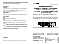
Designed to be installed in the TRANSITION Networks E-MCC-1600 Media
Converter Chassis, C/E-R-TX-FX-01 series redundant Fast Ethernet
™ media converters
connect 100BASE-TX unshielded twisted pair copper to 1300 nm 100BASE-FX
multimode OR to 1300 nm 100BASE-FX singlemode fiber. In the event of a failure
in the primary copper or fiber connection, a fully redundant secondary connection
is made available to the failed copper or fiber connection. Also, the copper and
fiber media converter interfaces operate independently, so that a failure on one
interface will not force a failure on the other interface.
Switches at the side of the media converter allow selection of auto-negotiation and
of full/half-duplex. Also, a port select timer (PST) switch* allows the network
administrator to set different timer values (used when a primary connection is lost
and a secondary connection is made) at each end of the copper/fiber interface.
(*See note on page 5.)
Minneapolis, MN 55344 USA
Redundant Fast Ethernet
™
100BASE-TX/100BASE-FX 1300 Nanometer
Slide-In-Module Media Converters
C/E-R-TX-FX-01, C/E-R-TX-FX-01(SC), C/E-R-TX-FX-01(SM)
USER’S GUIDE
C/E-R-TX-FX-01
Provides two (2) RJ-45 twisted pair
100BASE-TX connectors and two (2)
sets of RX (receive) and TX (transmit)
ST 100BASE-FX connectors to 1300
nm multimode fiber-optic cable.
C/E-R-TX-FX-01(SC)
Provides two (2) RJ-45 twisted pair
100BASE-TX connectors and two (2)
sets of RX (receive) and TX (transmit)
SC 100BASE-FX connectors to 1300
nm multimode fiber-optic cable.
C/E-R-TX-FX-01(SM)
Provides two (2) RJ-45 twisted pair
100BASE-TX connectors and two (2)
sets of RX (receive) and TX (transmit)
SC 100BASE-FX connectors to 1300
nm singlemode fiber-optic cable.
Power Modules
Media
Conversion
Center
Power
In Use
Power
In Use
1
2
Management
Module
Power
Link
TX
RX
CAUTION: RJ connectors are NOT INTENDED FOR CONNECTION TO THE
PUBLIC TELEPHONE NETWORK. Failure to observe this caution could result in
damage to the public telephone network.
Der Anschluss dieses Gerätes an ein öffentlickes Telekommunikationsnetz in den EG-Mitgliedstaaten
verstösst gegen die jeweligen einzelstaatlichen Gesetze zur Anwendung der Richtlinie 91/263/EWG zur
Angleichung der Rechtsvorschriften der Mitgliedstaaten über Telekommunikationsendeinrichtungen
einschliesslich der gegenseitigen Anerkennung ihrer Konformität.
C/E-R-TX-FX-01 in the Network . . . . . .2
Installation . . . . . . . . . . . . . . . . . . . .3
Operation . . . . . . . . . . . . . . . . . . . . .4
Fault Isolation and Correction . . . . .5
Cable Specifications . . . . . . . . . . . . .6
Technical Specifications . . . . . . . . . .7
Compliance Information . . . . . . . . . .8

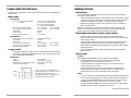
C/E-R-TX-FX-01 IN THE NETWORK
Recessed switches located on each side of the media converter are used to
configure the media converter for the network.
NOTE: Switch labels are located
AT TOP of C/E-R-TX-FX-01 media converter.
MDI/MDI-X SWITCHES
(One for each RJ-45 port - located one on each side of media
converter) Allows straight-through twisted-pair cable to be
used for crossover 100BASE-TX connections.
4-POSITION SWITCH (3rd switch not used)
Auto-negotiation (UP) Detects and adapts to line speed and
operating mode of attached device.
Full/Half-duplex (UP) Allows an attached full-duplex station to
transmit and receive simultaneously. (DOWN) Allows an
attached station to transmit and receive sequentially.
Port Select Timer (UP) Selects timer duration of eleven (11) seconds.
(DOWN) Selects timer duration of five (5) seconds.
TECHNICAL SPECIFICATIONS
Standards IEEE 802.3
Case Dimensions 5.7" x 3.0" x 1.8" (145mm x 76mm x 46mm)
Shipping Weight 3 pounds (1.4 kilograms)
Delay 400nsec round trip
Environment Temperature: 0-50°C (32° to 122° F )
Humidity 10-90%, non condensing
Altitude 0-10,000 feet
Power Supply Requirements Replace power supply with only the equivalent
input rating (see below) and output rating (unregulated 9-24VDC, 5.5W).
TN PN Requirement Location
3507 240 volts, 50 hertz United Kingdom
3342 230 volts, 50 hertz Europe
3340 120 volts, 60 hertz USA/Canada/Mexico
3346 100 volts, 50-60 hertz Japan
3511 240 volts, 50 hertz Australia
3537 (with power cord: 3522) South Africa
Warranty Lifetime
NOTE: Media Converter Slide-in-Modules can be installed in any
installation slot, in any order.
DECLARATION OF CONFORMITY
Name of Mfg: Transition Networks
6475 City West Parkway, Minneapolis MN 55344 USA
Model: Redundant Fast Ethernet
™
Media Converters
Part Number: C/E-R-TX-FX-01
Regulation: EMC Directive 89/336/EEC
Purpose: To declare that the C/E-R-TX-FX-01 to which this declaration refers is
in conformity with the following standards.
EMC-CISPR 22: 1985 Class A; EN 55022: 1988 Class A; EN 50082-1:1992;
EN 60950 A4:1997; IEC 801.2, IEC 801.3, and IEC 801.4; IEC 950
I, the undersigned, hereby declare that the equipment specified above conforms to the
above Directive(s) and Standard(s).
_May 1, 1999_____
Stephen Anderson, Vice-President of Engineering Date
2 kilometers - multimode
20 kilometers - singlemode
100 meters
100 meters
MDI switch setting
PST (DOWN) switch setting
MDI switch setting
PST (UP) switch setting
SWITCH
SWITCH
Do NOT connect media
converters between hubs.
Install no more than two (2)
media converters in series.

CABLE SPECIFICATIONS
The physical characteristics of the media cable must meet or exceed IEEE 802.3
specifications.
Fiber Cable
MULTIMODE
Fiber Optic Cable Recommended: 62.5 / 125 µm multimode fiber
Optional: 100 / 140 µm multimode fiber
85 / 125 µm multimode fiber
50 / 125 µm multimode fiber
Fiber Optic Transmitter Power: min: -19.0 dBm max: -14.0 dBm
Fiber Optic Receiver Sensitivity: min: -32.5 dBm max: -14.0 dBm
Wavelength : 850nM
Bit error rate: ≤10-9
Maximum Cable Distance: 2 kilometers
SINGLEMODE
Fiber Optic Cable Recommended: 9 µm singlemode fiber
Wavelength: 1300nM
Bit error rate: ≤10-9
Fiber-optic Transmitter Power: min: -15.0 dBm max: -8.0 dBm
Fiber-optic Receiver Sensitivity: min: -32.5 dBm max: -8.0 dBm
Maximum Cable Distance: 20 kilometers
Copper Cable
Category 5 twisted-pair copper wire is required. Either shielded twisted-
pair (STP) or unshielded twisted-pair (UTP) can be used. DO NOT USE
FLAT OR SILVER SATIN WIRE.
CATEGORY 5:
Gauge 24 to 22 AWG
Attenuation 20 dB/1000’ @ 10 MHz
Differential Characteristic Impedance 100 Ω ±10% @ 10 MHz
Maximum Cable Distance: 100 meters
INSTALLATION
Set Switches
Use small flatblade screwdriver or similar device to set recessed switches
according to site installation.
• Set EACH MDI/MDI-X switch to MDI for cable connection between switch
and media converter OR to MDI-X for cable connection between media
converter and terminal, transceiver or network interface card (NIC).
• Referring to drawing on page 2, set four-position switch according to
network configuration.
NOTE: If connecting two (2) media converters in series, set the PST (#4)
switch on one media converter to the UP position AND set the PST (#4)
switch on the other media converter to the DOWN position.
Install Slide-In-Module in E-MCC-1600 Chassis
• Remove Media Converter Slide-in-Module protective plate from
selected installation slot by removing two (2) screw that secures plate to
front of E-MCC-1600.
• Carefully slide Media Converter Slide-in-Module into installation slot,
aligning Media Converter Slide-in-Module with installation guides.
NOTE: Ensure that the Media Converter Slide-in-Module is firmly seated
against backplane.
• Secure Slide-in-Module by installing panel fastener screw attached to
Slide-in-Module.
Install Cable
COPPER
NOTE: KEEP TWISTED PAIR RUNS AS SHORT AS POSSIBLE.
• Locate or build 802.3 compliant cables with straight through
configuration and male RJ-45 plug connectors.
• Connect male RJ-45 plug connector at one end of cable to media
converter RJ-45 jack connector.
• Connect male RJ-45 plug connector at other end of cable to DTE
terminal RJ-45 jack connector (with MDI switch set to MDI-X) or to
switch RJ-45 jack connector (with MDI switch set to MDI).
FIBER
• Locate or build 802.3 compliant fiber cable with male two-stranded TX to
RX connectors appropriate to the media converter installed at both ends.
• Connect male TX and RX cable connectors at one end of cable to TX
and RX female connectors, respectively, on media converter.
• Connect male TX and RX cable connectors at other end of cable to RX
and TX connectors of 802.3 compliant fiber device.
(continued on next page)
The two active pairs in a 100BASE-TX
network are pins 1 & 2 and pins 3 & 6. Use
only dedicated wire pairs (such as
blue/white & white/blue, orange/white &
white/orange) for the active pins.
1
2
3
6
Twisted
Pair #1
Twisted
Pair #2
Straight Through Cable
1
2
3
6

INSTALLATION
(continued)
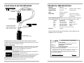
Connect to Power
• Install Power Adapter cord at back of media converter.
• Connect Power Adapter 3-prong plug to AC power.
• Verify that media converter is powered by observing illuminated LED(s).
OPERATION
After installation, the media converter should function without operator
intervention.
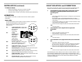
Status LEDs:
Use the status LEDs to monitor media converter operation in the network.
NOTE: lluminated PRI(mary) and/or SEC(ondary)
LEDs indicate media converter connection to
external power.
PRI Copper Primary Port - Steady green
LED indicates primary copper port is
being selected
by internal
control logic
SEC Copper
Secondary Port -
Steady green
LED indicates
secondary
copper port is
being selected
by internal control logic
RXC Receive Copper Port - Steady green
LED indicates valid data is being
detected on copper interface
SDC Signal Detect Copper - Steady green LED indicates Link
established on copper port selected
PRI: Fiber Primary Port - Steady green LED indicates primary fiber
port is being selected by internal control logic
SEC Fiber Secondary Port - Steady green LED indicates secondary
fiber port is being selected by internal control logic
SDF Signal Detect Fiber - Steady green LED indicates optical signal
present on fiber port selected
RXF Receive Fiber Port - Steady green LED indicates non-IDLE
symbols are being detected on fiber interface
FAULT ISOLATION and CORRECTION
If the media converter fails, isolate and correct the failure by determining the
answers to the following questions and then taking the indicated action:
1. Are the PRI(mary)/SEC(ondary) LEDs on the media converter
illuminated or alternating between between primary and
secondary ports?
NO
• Is the power adapter the proper type of voltage and cycle frequency
for AC outlet?
NOTE: Refer to the “Power Supply Requirements” on page 7.
• Is the power adapter properly installed in the media converter and
in the outlet?
• *Are PST switch settings on two media converters installed in series
in the network set to different values?
• Contact Technical Support at (800) 260-1312/ (800) LAN-WANS.
YES
• Proceed to step 2.
2. Is the 100BASE-TX SDC (Signal Detect/Copper) LED
illuminated?
NO
• Check UTP cables for proper connection.
• Verify MDI/MDI-X switch position.
• Contact Technical Support at (800) 260-1312/ (800) LAN-WANS.
YES
• Proceed to step 3.
3. Is the 100BASE-FX SDF (Signal Detect/Fiber) LED illuminated?
NO
• Check fiber cables for proper connection.
• Verify that TX and RX cables on media converter are connected to
RX and TX ports, respectively, on the other 100BASE-FX device.
• Refer to Tech Tips available at: http://www.transition.com
• Contact Technical Support at (800) 260-1312/ (800) LAN-WANS.
YES
• Contact Technical Support at (800) 260-1312/ (800) LAN-WANS.
*NOTE: Setting PST switch settings on two media converters installed in series
in the network to different values (11 seconds and 5 seconds) ensures, in the
event of common power failure or similar incident, a sufficient delay in the time
required to establish each link so that communication between the media
converters is guaranteed.
PrimaryPrimary
100BASE-TX100BASE-TX
PrimaryPrimary
100BASE-FX100BASE-FX
SecondarySecondary
100BASE-TX100BASE-TX
SecondarySecondary
100BASE-FX100BASE-FX
RXC
RXF
SDF
SDC
PRI
SEC
PRI
SEC
RXC
SDC
PRI
SEC
RXF
SDF
SEC
PRI
-
 1
1
-
 2
2
-
 3
3
-
 4
4


Milan Technology C/E-R-TX-FX-01 Manuel utilisateur
- Taper
- Manuel utilisateur
- Ce manuel convient également à
dans d''autres langues
Autres documents
-
Transition Networks E-100BTX-FX-05(100) Manuel utilisateur
-
-
Allied Telesis MC102XL Guide d'installation
-
-
Transition Networks TN-CWDM-SFP-1290 Manuel utilisateur
-
LG-Ericsson ipecs ES-5048XG Guide d'installation
-
SMC Networks SMC8028L2 Manuel utilisateur
-
-
-