Marmitek 1082002 Manuel utilisateur
- Catégorie
- Composants de dispositif de sécurité
- Taper
- Manuel utilisateur
Ce manuel convient également à


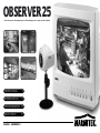
Congratulations! This Marmitek Observation System you have bought is a quality product, manufactured with high precision. Marmitek Observation
Systems are easy to install, and give you added security for many years. All items you need to hook up your Observation Systems are included in the
box. If you want to expand your system, an extensive range of camera’s and accessories is available. For more information visit www.marmitek.com.
Before you start, please read the installation and operating instructions in this manual, and keep it for future reference.
FEATURES
• Highly reliable stable circuit to assure best quality picture.
• Connect up to 4 cameras.
• Easy to install and operate.
• Compact, lightweight and versatile.
• High resolution monitor.
• Low, minimum lighting requirement.
• Manual or auto selector switch.
• 3 to 60 second auto switching speed adjustable.
• 2 way audio monitoring
• VCR outputs for VCR or time lapse recorder
• Camera cable extendable up to 100m
READ THE FOLLOWING PRECAUTIONS BEFORE INSTALLING OR USING THE SYSTEM
1. Choose an ideal location for the camera so that the lens won't be exposed to any direct light source. The camera unit must also be protected
against moisture and vibration.
2. The monitor should only be operated with the correct power source indicated on the specification.
3. Check the system for operation prior to installing the unit.
4. Be careful not to scratch the camera lens.
THE MARMITEK OBSERVER 25 KIT CONTAINS:
1. 25 cm black and white monitor with 4 channel auto camera switcher
2. 1/3" CCD Auto iris camera
3. 20m DIN cable for plug&play connection
2 MARMITEK
4. Camera bracket
5. Owner’s manual

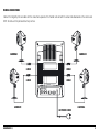
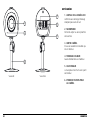
DESCRIPTION OF CONTROLS & OPERATION
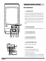
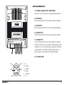
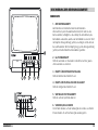
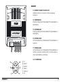
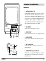
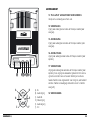
FRONT VIEW MONITOR UNIT
1. TIME CONTROL KNOB
To vary the display switching speed from 3 to 60 seconds. When
the system is in the auto mode with more than one camera, this
knob enables you to vary the time each camera picture will be dis-
played on the monitor. In order to increase the switching time, turn
this knob in clockwise direction. Turning this knob all the way in
counter clockwise direction will quickly step through the camera
images.
2. VOLUME CONTROL KNOB
Adjust the volume control knob to reach the desired volume level.
3. CONTRAST CONTROL KNOB
To adjust the CONTRAST of the screen.
4. BRIGHTNESS CONTROL KNOB
To adjust the BRIGHTNESS of the screen.
5. VERTICAL HOLD CONTROL KNOB
To adjust the VERTICAL synchronization.
6. VCR ON/OFF SELECTOR
Press it to review the video signal from the VCR.
Press it again to switch back to the camera signal.
VCR Recording Reviewing Method
1) Connect the monitor to the VCR and press the RECORD button
on the VCR to start recording the pictures. The VCR will record the
3OBSERVER25
1
2 3
6
5
4
PUSH
TALK
1
234
AUTO
POWER
7 11 8 9 10
12

actual picture as displayed on the monitor.
2) To review the recorded pictures, press the VCR button on the monitor and then the PLAY button on the VCR.
7. TALK BUTTON
Press and hold this button to talk through the loud speaker built into the camera and release it to receive audio from the camera’s microphone.
8. CAMERA-1,2,3,4 BUTTONS
Press the corresponding button on the monitor for the desired camera channel.
9. PROGRAMMABLE AUTO SEQUENCE
Turns on/off the Auto Sequence Mode. In auto mode the system will switch between preset camera channels at a time sequence set by the
dwell time adjuster. The sequencer is also programmable. Press and hold the auto button for 3 seconds, this will enable sequence memory
mode and cause the auto LED to flash. With the auto led flashing press the channel of each camera required to be included in the display
sequence (in the order that you wish them to be displayed).
When your selections are finished press the auto button in order to lock the memory.
IMPORTANT-This operation must be carried out when using less than 4 cameras in order to avoid switching to a blank screen.
NB: The memory will be lost if the power to the monitor is lost.
10. POWER CONTROL BUTTON
Press to turn on the power.
The screen will display the areas being monitored.
Press again to turn power OFF.
11. MICROPHONE
Pick up your voice and sounds near the monitor. As soon as the TALK button is activated, your voice will be heard through the loudspeaker of
the active camera (intercom function).
12. LED INDICATORS
LED POWER, AUTO, TALK, CAMERA 1
~
4 function indicators.
4 MARMITEK

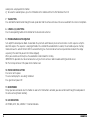
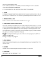
REAR VIEW MONITOR UNIT
13. CAMERA PLUG&PLAY INPUT CONNECTORS
Connect up to 4 cameras by these easy plug and play connectors.
14. VIDEO INPUT
Receives video signal from VCR / time lapse recorder for playback
15. AUDIO INPUT
Receives audio signal from VCR / time lapse recorder for playback
16. AUDIO OUTPUT
Transmits audio signal to VCR / time lapse recorder for recording.
17. VIDEO OUTPUT
Transmits video signal to VCR / time lapse recorder for recording.
Also used to send the camera signals to a second monitor (second
monitor will act as "slave" and will display a copy of the information
as displayed on the main monitor. Switching between camera
images is done on main monitor, slave monitor will follow).
18. AC POWER CORD
5OBSERVER25
13 17 16 15 14 18
C1 C2 C3 C4
D
E
F
A
B
C
A) B+
B) Audio in
C) Audio B+
D) Video in
E) Audio out
F) N.C

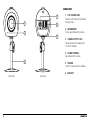
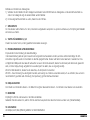
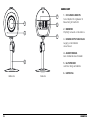
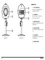
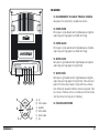
CAMERA UNIT
1. CCD CAMERA LENS
Fixed lens with built-in IR illumination
for night vision.
2. MICROPHONE
Pick up sound around the camera.
3. CAMERA OUTPUT JACK
For connection of the cable which
runs to the monitor.
4. ALARM TERMINAL
No function for this model.
5. SPEAKER
Deliver the sound from the monitor.
6. BRACKET
6 MARMITEK
Front View Rear View
3
5
4
1
2
6

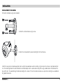
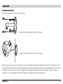
INSTALLATION
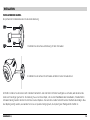
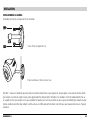
INSTALLATION OF THE CAMERA
Permanent installation using camera bracket:
1. Attach the camera bracket using 4 screws.
2. Attach the camera onto the pedestal and tighten the thumb screw.
CAUTION : Keep camera installed away from direct sunlight. Also avoid places where humidity is high or where the camera is not protected from
rain. The mounting bracket must be attached to a structural object such as a wall stud or ceiling rafter using suitable fastener. Do not touch the
glass of the lens. This could damage the delicate coating on its surface. If the lens has to be cleaned, use a special lens cleaning tissue available at
any good camera store.
7OBSERVER25

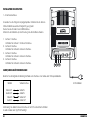
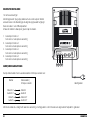
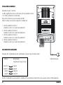
INSTALLATION OF THE MONITOR
1-4 Camera connections
Using the provided plug&play cable, connect the camera to the monitor as
shown in the diagram on the next page.
Plug the AC cord into an 230V outlet
Power the monitor by pressing the green power button
1. Camera 1 Terminal
Connect camera 1 cable to this terminal
2. Camera 2 Terminal
Connect camera 2 cable to this terminal.
3. Camera 3 Terminal
Connect camera 3 cable to this terminal.
4. Camera 4 Terminal
Connect camera 4 cable to this terminal.
AUDIO/VIDEO JACK CONNECTIONS.
Refer to the following connection method, for connecting a VCR or time lapse recorder
Monitor VCR Terminal
Video OUT Video IN
Audio OUT Audio IN
Video IN Video OUT
Audio IN Audio OUT
NOTE : The cable for this connection is not supplied with the unit.
An "RCA" type cable is required.
8 MARMITEK
1
2
3
4
C1 C2 C3 C4
AC power cord

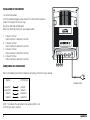
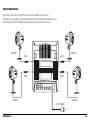
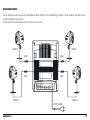
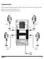
WIRING CONNECTIONS
Connect the Plug&Play Din Jack cable with the arrow mark upwards at the monitor side and with the arrow mark downwards at the camera side
NOTE: Do not use RCA jack to connect any camera.
9OBSERVER25
C1 C2 C3 C4
AC POWER CORD
CAMERA1
CAMERA2 CAMERA3
CAMERA4
CABLE
CABLE CABLE
CABLE

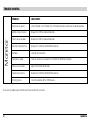
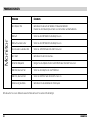
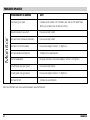
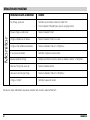
TROUBLE SHOOTING
PROBLEM CHECK POINT:
No picture, no sound Check if monitor is in VCR mode. Press VCR on/off selector to switch over to normal operation.
Multiple image in picture Readjust the VERTICAL Hold control knob.
Picture rolls up or down Readjust the VERTICAL Hold control knob.
Too dark or bright picture. Readjust the CONTRAST or BRIGHTNESS controls.
No Power Check for AC connection.
Poor picture quality Clean the camera lens. Readjust the CONTRAST or BRIGHTNESS controls.
Picture, but no sound Adjust the VOLUME control knob.
Sound, but no picture Readjust the CONTRAST or BRIGHTNESS controls.
Shrinking picture Check the condition of the POWER source.
Please visit our website www.marmitek.com if you need further assistance.
10 MARMITEK
Monitor

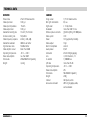
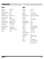
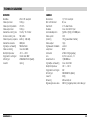
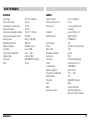
TECHNICAL DATA
MONITOR
Picture tube 25cm CRT black & white
Video input level 1.0V p-p
Video input impedance 75 ohm
Video output level 1.0V p-p
Horizontal Scanning rate 15.625 / 15.734 KHz
Vertical scanning rate 50 / 60 Hz
Video frequency response 6MHz (+ 1dB,-3dB)
Horizontal resolution 800 lines or better
Signal to noise ratio 50 dB or Better
Video amplifier circuit More Than 30dB
Operating temperature -10˚C
~
+50˚C
Power consumption less than 40W
Dimensions 250x250x255mm (wxdxh)
Weight 4,64 kg
CAMERA
Image sensor 1/3" CCD black & white
Min. light illumination 0,1 Lux
Night vision ± 1m by IR leds
Resolution more than 380 TV lines
Effective picture elements (V)492 x H(512) / 251.000 pixels
Video system CCIR
Power 12V (supplied by monitor)
Video output 1Vpp
Built in microphone electret
Loud speaker 0,5W
Connector 6P Mini DIN (plug&play)
Lens 4,3mm fixed lens, 73˚
Iris control 1/100.000 sec.
S/N ratio more than 45 dB
Operating temperature -10˚C
~
+50˚C
Power consumption 2W
Dimensions 50x70x50mm (wxdxh)
Weight 230g
Cabinet ABS plastic, white
Accessories included 20m HQ plug&play cable,
camera bracket
11OBSERVER25

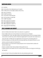
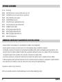
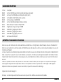
OPTIONAL ACCESSORIES:
Part. No. Description
09324 CA159 B/W Camera with fixed lens (camera as provided in set)
09325 CA159M B/W Camera C/CS without lens (lens 4,6,12,16mm)
09328 CAD611 B/W dome camera, shock proof
09345 CA162WP B/W outdoor camera
09331 CA168 B/W camera in smoke detector housing
09333 CH112 outdoor housing for CA159/CA159M
09332 TLV9600 time lapse recorder
09164 20m HQ plug&play cable 6P Mini DIN
09165 40m HQ plug&play cable 6P Mini DIN
09166 100m HQ plug&play cable 6P Mini DIN
09167 6P/6P Mini DIN extension connector
CARE, MAINTENANCE AND SAFEGUARDS
• Keep your monitor and camera dry. When the units become wet, dry them immediately.
• Keep the unit away from excessive dirt and dust. These can cause premature wear of parts.
• Ventilation slots and openings in the cabinet and the back or bottom are provided for ventilation and to ensure reliable operation of the
equipment and to protect it from overheating. These openings must not be blocked or covered. The equipment should never be placed near or
over a radiator. The monitor should never be placed in a built-in installation such as bookcase, unless proper ventilation is provided.
• Do not attempt to service this equipment yourself as opening or removing covers may expose you to dangerous voltage or other hazards. Refer
all dervicing to qualified service personnel.
• Use and store your unit in normal temperature environment. Extreme temperatures can shorten the life of electronic devices.
• Handle the monitor carefully. Dropping it can cause serious damage to the unit.
• Clean the unit with a damp cloth to keep it looking new. Do not use harsh chemicals, cleaning solvents, or strong detergents to clean the unit.
This equipment is CE approved.
NOTE: All specifications are subect to change without notice.
12 MARMITEK

OBSERVER 25
Herzlichen Glückwunsch zum Kauf dieses Marmitek Überwachungssystems. Dieses Marmitek Überwachungssystem ist ein Qualitätserzeugnis, das
mit grösster Sorgfalt hergestellt wurde. Marmitek Überwachungssysteme sind einfach zu installieren und geben Ihnen zusätzliche Sicherheit für viele
Jahre. Alle Teile um Ihre Überwachungsanlage anzuschliessen, befinden sich in diesem Karton. Wenn Sie Ihr System erweitern möchten, so stehen
eine grosse Auswahl an Kameras und Zubehör zur Verfügung. Mehr Informationen erhalten Sie unter www.marmitek.com.
Bitte lesen Sie diese Installations- und Gebrauchsanweisung sorgfältig und bewahren Sie diese für künftige Gelegenheiten.
EIGENSCHAFTEN
• sehr stabile Schaltungen garantieren beste Bildqualität
• Anschlüsse für bis zu 4 Kameras
• Einfach zu installieren und zu bedienen
• Kompakt, leicht und vielseitig
• Hochauflösender Monitor
• Wenig Licht erforderlich
• Automatisches oder manuelles Umschalten
• Umschaltzeit einstellbar von 3 bis 60 Sekunden
• 2-Weg Audiosystem
• VCR-Ausgänge für Videorekorder oder TimeLapseRekorder
• Kamerakabel bis 100 m verlängerbar
LESEN SIE DIE FOLGENDEN VORSORGEMASSNAHMEN BEVOR SIE DAS SYSTEM INSTALLIEREN ODER GEBRAUCHEN.
1. Wählen Sie einen idealen Standort für die Kamera, so dass das Objektiv keiner direkten Lichtquelle ausgesetzt ist.
Die Kamera muss vor Feuchtigkeit und Erschütterungen geschützt sein.
2. Der Monitor muss an die richtige Stromquelle angeschlossen werden, so wie in der Anleitung beschrieben.
3. Überprüfen Sie den Betrieb des Systems bevor Sie das Gerät installieren.
13OBSERVER25

4. Achten Sie besonders darauf, die Linse des Objektivs nicht zu beschädigen.
DAS OBSERVER 25 SET ENTHÄLT:
1. 25 cm s/w-Monitor mit automatischem 4-Kanal-Umschalter
2. 1/3" CCD Auto-Iris-Kamera
3. 20m DIN-Kabel für plug&play-Anschluss
4. Kamerahalterung
5. Betriebsanleitung
14 MARMITEK

BESCHREIBUNG DER BEDIENUNGSELEMENTE
VORDERSEITE
1. ZEITKONTROLLKNOPF
Zum Einstellen der Umschaltzeit von 3 bis 60 Sekunden.
Wenn sich das System im automatischen Stand, mit mehr als einer
Kamera befindet, ermöglicht es dieser Knopf, die Umschaltzeit jedes
Kamerabildes einzustellen, welches auf dem Monitor zu sehen ist. Wird
der Knopf in Uhrzeigerrichtung gedreht, so verlängert sich die Zeit auf
bis zu 60 Sekunden. Wird der Knopf ganz gegen die Uhrzeigerrichtung
gedreht, wird schnell durch die Kamerabilder geschaltet.
2. LAUTSTÄRKEKNOPF
Stellt die Lautstärke ein. Rauf- oder runterdrehen um die gewün-
schte Lautstärke zu erreichen.
3. KNOPF FÜR KONTRASTEINSTELLUNG
Stellt den Kontrast des Bildschirms ein.
4. KNOPF ZUR EINSTELLUNG DER HELLIGKEIT
Stellt die Helligkeit des Bildschirms ein.
5. VERTIKALER FESTSTELLKNOPF
Stellt die verticale Synchronisation ein.
6. VIDEO EIN/AUS-SCHALTER
Den Schalter drücken, um das Videosignal des Gerätes zu erhalten.
Erneut drücken um zum Kamerasignal zurückzugehen.
15OBSERVER25
1
2 3
6
5
4
PUSH
TALK
1
234
AUTO
POWER
7 11 8 9 10
12

Methode zum Einstellen des Videosignales:
1) Verbinden Sie den Monitor mit dem Videogerät und drücken Sie die RECORD-Taste des Videogerätes um die Aufnahme der Bilder zu
starten. Das Videogerät zeigt die aktuellen Bilder auf dem Monitor.
2) Um die aufgenommenen Bilder zu sehen, drücken Sie die VCR-Taste.
7. SPRACHTASTE
Die Taste drücken und festhalten um in den, in die Kamera eingebauten Lautsprecher zu sprechen und loslassen, um Empfang vom Mikrofon
der Kamera zu erhalten.
8. TASTEN FÜR KAMERAS 1,2,3,4
Drücken Sie eine der Tasten, um den gewählten Kamerakanal anzuzeigen.
9. PROGRAMMIERBARE AUTO-REIHENFOLGE
Ein/Ausschalter für die Einstellung der Auto-Reihenfolge.
In der Auto-Einstellung wird das System zwischen den eingestellten Kamerakanälen schalten, wenn die zeitliche Reihenfolge mit dem
Zeitschalter eingestellt wurde. Der Zeitschalter ist ebenfalls programmierbar. Drücken und halten Sie die Auto-Taste 3 Sekunden fest. Dies
ermöglicht dem Bildspeicher das Auto-LED aufleuchten zu lassen. Brennt das Auto-LED, drücken Sie den Kanal jeder Kamera die gewünscht
wird, um in die Display-Anzeige aufgenommen zu werden (wenn Sie wollen, dass sie angezeigt werden).
Wenn Ihre Wahl beendet ist, drücken Sie die Auto-Taste, um den Speicher festzustellen.
WICHTIG – Diese Einstellung muss durchgeführt werden, wenn weniger als 4 Kameras verwendet werden, um zu verhindern, dass auf einen
leeren Bildschirm geschaltet wird. Anmerkung: Die Speicherung geht bei Stromausfall verloren.
10. EIN/AUS-SCHALTER
Den Schalter zum Einschalten drücken. - Der Bildschirm zeigt den überwachten Bereich. - Den Schalter erneut drücken zum Ausschalten.
11. MIK ROFON
Empfängt Ihre Stimme und Geräusche in der Nähe des Monitors.
Sobald die TALK-Taste aktiviert ist, wird Ihre Stimme durch den Lautsprecher der aktivierten Kamera zu hören sein. (Interkomfunktion).
12. LED-ANZEIGE
LED-EIN/AUS, AUTO,TALK (SPRACHE), KAMERA 1-4 FUNKTIONSANZEIGE.
16 MARMITEK

RÜCKSEITE
13. KAMERA PLUG&PLAY-ANSCHLÜSSE
Verbindet einfach bis zu 4 Kameras mit diesen plug&play-
Anschlüssen.
14. VIDEOEINGANG
Empfängt Videosignal vom Videorekorder/TimeLapseRekorder zur
Wiederholung.
15. AUDIOEINGANG
Empfängt Audiosignal vom Videorekorder/TimeLapseRekorder zur
Wiederholung.
16. AUDIOAUSGANG
Leitet das Audiosignal zum Videorekorder/TimeLapseRekorder zur
Aufnahme.
17. VIDEOAUSGANG
Leitet das Videosignal zum Videorekorder/TimeLapseRekorder zur
Aufnahme. Kann auch verwendet werden, um Kamerasignale zu
einem zweiten Monitor zu übertragen.
18. AC STROMKABEL
17OBSERVER25
13 17 16 15 14 18
C1 C2 C3 C4
D
E
F
A
B
C
A) B+
B) Audio in
C) Audio B+
D) Video in
E) Audio out
F) N.C

KAMERA UNIT
1. CCD KAMERA OBJEKTIV
Festes Objektiv mit eingebauter IR-
Beleuchtung für Nachtsicht.
2. MIKROFON
Empfängt Geräusche um die Kamera.
3. KAMERA OUTPUT-ANSCHLUSS
Ausgang um den Monitor
anzuschliessen.
4. ALARM TERMINAL
Keine Funktion bei diesem Modell.
5. LAUTSPRECHER
Liefert den Klang vom Monitor.
6. HALTERUNG
18 MARMITEK
3
5
4
1
2
6
Vorderseite Rückseite

INSTALLATION
INSTALLATION DER KAMERA
Bei permanenter Installation benutzen Sie die Kamerahalterung.
1. Verbinden Sie die Kamera und Halterung mit den 4 Schrauben.
2. Verbinden Sie die Kamera mit dem Sockel und drehen Sie die Schraube fest an.
ACHTUNG: Installieren Sie die Kamera nicht in direktem Sonnenlicht. Auch sind Stellen mit hoher Feuchtigkeit zu vermeiden, oder bei denen die
Kamera nicht vor Regen geschützt ist. Die Halterung muss an ein festes Objekt, z.B. an einem Wandbalken oder Deckenbalken, mit ordentlichen
Schrauben befestigt werden. Berühren Sie nicht das Glas des Objektives. Dies kann den sensiblen Schutzfilm auf der Oberfläche beschädigen. Muss
das Objektiv gereinigt werden, so verwenden Sie hierzu ein spezielles Reinigungstuch, das in jedem guten Photogeschäft erhältlich ist.
19OBSERVER25

INSTALLATION DES MONITORS
1 – 4 Kameraanschlüsse
Verwenden Sie das mitgelieferte plug&play-Kabel. Verbinden Sie die Kamera
mit dem Monitor wie auf dem Diagramm gezeigt wird.
Stecken Sie das AC-Kabel in den 230V Anschluss.
Schalten Sie den Monitor ein, indem Sie die grüne Einschalttaste drücken.
1. Kamera 1 Anschluss
Verbinden Sie Kamera 1 mit diesem Anschluss.
2. Kamera 2 Anschluss
Verbinden Sie Kamera 2 an diesem Anschluss.
3. Kamera 3 Anschluss
Verbinden Sie Kamera 3 an diesem Anschluss.
4. Kamera 4 Anschluss
Verbinden Sie Kamera 4 an diesem Anschluss.
AUDIO/VIDEO GERÄTEVERBINDUNGEN
Beachten Sie die folgende Verbindungsmethode zum Anschluss eines Video- oder TimeLapseRekorders.
Monitor Video-Anschluss
Video OUT Video IN
Audio OUT Audio IN
Video IN Video OUT
Audio IN Audio OUT
Anmerkung: Das Kabel für diesen Anschluss ist nicht im Lieferumfach enthalten.
Es wird ein Kabel vom Typ "RCA" benötigt.
20 MARMITEK
1
2
3
4
C1 C2 C3 C4
AC Stromkabel
La page charge ...
La page charge ...
La page charge ...
La page charge ...
La page charge ...
La page charge ...
La page charge ...
La page charge ...
La page charge ...
La page charge ...
La page charge ...
La page charge ...
La page charge ...
La page charge ...
La page charge ...
La page charge ...
La page charge ...
La page charge ...
La page charge ...
La page charge ...
La page charge ...
La page charge ...
La page charge ...
La page charge ...
La page charge ...
La page charge ...
La page charge ...
La page charge ...
La page charge ...
La page charge ...
La page charge ...
La page charge ...
-
 1
1
-
 2
2
-
 3
3
-
 4
4
-
 5
5
-
 6
6
-
 7
7
-
 8
8
-
 9
9
-
 10
10
-
 11
11
-
 12
12
-
 13
13
-
 14
14
-
 15
15
-
 16
16
-
 17
17
-
 18
18
-
 19
19
-
 20
20
-
 21
21
-
 22
22
-
 23
23
-
 24
24
-
 25
25
-
 26
26
-
 27
27
-
 28
28
-
 29
29
-
 30
30
-
 31
31
-
 32
32
-
 33
33
-
 34
34
-
 35
35
-
 36
36
-
 37
37
-
 38
38
-
 39
39
-
 40
40
-
 41
41
-
 42
42
-
 43
43
-
 44
44
-
 45
45
-
 46
46
-
 47
47
-
 48
48
-
 49
49
-
 50
50
-
 51
51
-
 52
52


Marmitek 1082002 Manuel utilisateur
- Catégorie
- Composants de dispositif de sécurité
- Taper
- Manuel utilisateur
- Ce manuel convient également à
dans d''autres langues
- Deutsch: Marmitek 1082002 Benutzerhandbuch
- Nederlands: Marmitek 1082002 Handleiding
Documents connexes
-
Marmitek VIDEO DOORPHONE Le manuel du propriétaire
-
Marmitek MEGACAM1 Manuel utilisateur
-
-
Marmitek GIGACAM 4 Manuel utilisateur
-
-
-
Marmitek PROTECTOR 28 Manuel utilisateur
-
-
Marmitek DoorGuard 300 Manuel utilisateur