Lincoln Electric 215 Manuel utilisateur
- Catégorie
- Système de soudage
- Taper
- Manuel utilisateur
Ce manuel convient également à

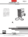
POWER MIG
™
215
OPERATOR’S MANUAL
IM828-A
April, 2007
Safety Depends on You
Lincoln arc welding and cutting
equipment is designed and built
with safety in mind. However, your
overall safety can be increased by
proper installation ... and thought-
ful operation on your part. DO
NOT INSTALL, OPERATE OR
REPAIR THIS EQUIPMENT
WITHOUT READING THIS
MANUAL AND THE SAFETY
PRECAUTIONS CONTAINED
THROUGHOUT. And, most
importantly, think before you act
and be careful.
For use with machine Code Numbers
1111007700,, 1111009999,, 1111224477
For use with machine Code Numbers
• Sales and Service through Subsidiaries and Distributors Worldwide •
Cleveland, Ohio 44117-1199 U.S.A. TEL: 216.481.8100 FAX: 216.486.1751 WEB SITE: www.lincolnelectric.com
• World's Leader in Welding and Cutting Products •
Copyright © 2007 Lincoln Global Inc.
R
C
UL
RETURN TO MAIN MENU

FOR ENGINE
powered equipment.
1.a. Turn the engine off before troubleshooting and maintenance
work unless the maintenance work requires it to be running.
____________________________________________________
1.b.Operate engines in open, well-ventilated
areas or vent the engine exhaust fumes
outdoors.
____________________________________________________
1.c. Do not add the fuel near an open flame
welding arc or when the engine is running.
Stop the engine and allow it to cool before
refueling to prevent spilled fuel from vaporiz-
ing on contact with hot engine parts and
igniting. Do not spill fuel when filling tank. If
fuel is spilled, wipe it up and do not start
engine until fumes have been eliminated.
____________________________________________________
1.d. Keep all equipment safety guards, covers and devices in
position and in good repair.Keep hands, hair, clothing and
tools away from V-belts, gears, fans and all other moving
parts when starting, operating or repairing equipment.
____________________________________________________
1.e. In some cases it may be necessary to remove safety
guards to perform required maintenance. Remove
guards only when necessary and replace them when the
maintenance requiring their removal is complete.
Always use the greatest care when working near moving
parts.
___________________________________________________
1.f. Do not put your hands near the engine fan.
Do not attempt to override the governor or
idler by pushing on the throttle control rods
while the engine is running.
___________________________________________________
1.g. To prevent accidentally starting gasoline engines while
turning the engine or welding generator during maintenance
work, disconnect the spark plug wires, distributor cap or
magneto wire as appropriate.
i
SAFETY
i
ARC WELDING CAN BE HAZARDOUS. PROTECT YOURSELF AND OTHERS FROM POSSIBLE SERIOUS INJURY OR DEATH.
KEEP CHILDREN AWAY. PACEMAKER WEARERS SHOULD CONSULT WITH THEIR DOCTOR BEFORE OPERATING.
Read and understand the following safety highlights. For additional safety information, it is strongly recommended that you pur-
chase a copy of “Safety in Welding & Cutting - ANSI Standard Z49.1” from the American Welding Society, P.O. Box 351040,
Miami, Florida 33135 or CSA Standard W117.2-1974. A Free copy of “Arc Welding Safety” booklet E205 is available from the
Lincoln Electric Company, 22801 St. Clair Avenue, Cleveland, Ohio 44117-1199.
BE SURE THAT ALL INSTALLATION, OPERATION, MAINTENANCE AND REPAIR PROCEDURES ARE
PERFORMED ONLY BY QUALIFIED INDIVIDUALS.
WARNING
Mar ʻ95
ELECTRIC AND
MAGNETIC FIELDS
may be dangerous
2.a. Electric current flowing through any conductor causes
localized Electric and Magnetic Fields (EMF). Welding
current creates EMF fields around welding cables and
welding machines
2.b. EMF fields may interfere with some pacemakers, and
welders having a pacemaker should consult their physician
before welding.
2.c. Exposure to EMF fields in welding may have other health
effects which are now not known.
2.d. All welders should use the following procedures in order to
minimize exposure to EMF fields from the welding circuit:
2.d.1.
Route the electrode and work cables together - Secure
them with tape when possible.
2.d.2. Never coil the electrode lead around your body.
2.d.3. Do not place your body between the electrode and
work cables. If the electrode cable is on your right
side, the work cable should also be on your right side.
2.d.4. Connect the work cable to the workpiece as close as
possible to the area being welded.
2.d.5. Do not work next to welding power source.
1.h. To avoid scalding, do not remove the
radiator pressure cap when the engine is
hot.
CALIFORNIA PROPOSITION 65 WARNINGS
Diesel engine exhaust and some of its constituents
are known to the State of California to cause can-
cer, birth defects, and other reproductive harm.
The engine exhaust from this product contains
chemicals known to the State of California to cause
cancer, birth defects, or other reproductive harm.
The Above For Diesel Engines
The Above For Gasoline Engines
POWER MIG 215

ii
SAFETY
ii
ARC RAYS can burn.
4.a. Use a shield with the proper filter and cover
plates to protect your eyes from sparks and
the rays of the arc when welding or observing
open arc welding. Headshield and filter lens
should conform to ANSI Z87. I standards.
4.b. Use suitable clothing made from durable flame-resistant
material to protect your skin and that of your helpers from
the arc rays.
4.c. Protect other nearby personnel with suitable, non-flammable
screening and/or warn them not to watch the arc nor expose
themselves to the arc rays or to hot spatter or metal.
ELECTRIC SHOCK can
kill.
3.a. The electrode and work (or ground) circuits
are electrically “hot” when the welder is on.
Do not touch these “hot” parts with your bare
skin or wet clothing. Wear dry, hole-free
gloves to insulate hands.
3.b. Insulate yourself from work and ground using dry insulation.
Make certain the insulation is large enough to cover your full
area of physical contact with work and ground.
In addition to the normal safety precautions, if welding
must be performed under electrically hazardous
conditions (in damp locations or while wearing wet
clothing; on metal structures such as floors, gratings or
scaffolds; when in cramped positions such as sitting,
kneeling or lying, if there is a high risk of unavoidable or
accidental contact with the workpiece or ground) use
the following equipment:
• Semiautomatic DC Constant Voltage (Wire) Welder.
• DC Manual (Stick) Welder.
• AC Welder with Reduced Voltage Control.
3.c. In semiautomatic or automatic wire welding, the electrode,
electrode reel, welding head, nozzle or semiautomatic
welding gun are also electrically “hot”.
3.d. Always be sure the work cable makes a good electrical
connection with the metal being welded. The connection
should be as close as possible to the area being welded.
3.e. Ground the work or metal to be welded to a good electrical
(earth) ground.
3.f.
Maintain the electrode holder, work clamp, welding cable and
welding machine in good, safe operating condition. Replace
damaged insulation.
3.g. Never dip the electrode in water for cooling.
3.h. Never simultaneously touch electrically “hot” parts of
electrode holders connected to two welders because voltage
between the two can be the total of the open circuit voltage
of both welders.
3.i. When working above floor level, use a safety belt to protect
yourself from a fall should you get a shock.
3.j. Also see Items 6.c. and 8.
POWER MIG 215
FUMES AND GASES
can be dangerous.
5.a.Welding may produce fumes and gases
hazardous to health. Avoid breathing these
fumes and gases. When welding, keep
your head out of the fume. Use enough
ventilation and/or exhaust at the arc to keep
fumes and gases away from the breathing zone. When
welding with electrodes which require special
ventilation such as stainless or hard facing (see
instructions on container or MSDS) or on lead or
cadmium plated steel and other metals or coatings
which produce highly toxic fumes, keep exposure as
low as possible and below Threshold Limit Values (TLV)
using local exhaust or mechanical ventilation. In
confined spaces or in some circumstances, outdoors, a
respirator may be required. Additional precautions are
also required when welding on galvanized steel.
5. b. The operation of welding fume control equipment is affected
by various factors including proper use and positioning of
the equipment, maintenance of the equipment and the spe-
cific welding procedure and application involved. Worker
exposure level should be checked upon installation and
periodically thereafter to be certain it is within applicable
OSHA PEL and ACGIH TLV limits.
5.c.
Do not weld in locations near chlorinated hydrocarbon
vapors
coming from degreasing, cleaning or spraying operations.
The heat and rays of the arc can react with solvent vapors
to
form phosgene, a highly toxic gas, and other irritating prod-
ucts.
5.d. Shielding gases used for arc welding can displace air and
cause injury or death. Always use enough ventilation,
especially in confined areas, to insure breathing air is safe.
5.e. Read and understand the manufacturerʼs instructions for this
equipment and the consumables to be used, including the
material safety data sheet (MSDS) and follow your
employerʼs safety practices. MSDS forms are available from
your welding distributor or from the manufacturer.
5.f. Also see item 1.b.
AUG 06

FOR ELECTRICALLY
powered equipment.
8.a. Turn off input power using the disconnect
switch at the fuse box before working on
the equipment.
8.b. Install equipment in accordance with the U.S. National
Electrical Code, all local codes and the manufacturerʼs
recommendations.
8.c. Ground the equipment in accordance with the U.S. National
Electrical Code and the manufacturerʼs recommendations.
CYLINDER may explode
if damaged.
7.a. Use only compressed gas cylinders
containing the correct shielding gas for the
process used and properly operating
regulators designed for the gas and
pressure used. All hoses, fittings, etc. should be suitable for
the application and maintained in good condition.
7.b. Always keep cylinders in an upright position securely
chained to an undercarriage or fixed support.
7.c. Cylinders should be located:
•Away from areas where they may be struck or subjected to
physical damage.
•A safe distance from arc welding or cutting operations and
any other source of heat, sparks, or flame.
7.d. Never allow the electrode, electrode holder or any other
electrically “hot” parts to touch a cylinder.
7.e. Keep your head and face away from the cylinder valve outlet
when opening the cylinder valve.
7.f. Valve protection caps should always be in place and hand
tight except when the cylinder is in use or connected for
use.
7.g. Read and follow the instructions on compressed gas
cylinders, associated equipment, and CGA publication P-l,
“Precautions for Safe Handling of Compressed Gases in
Cylinders,” available from the Compressed Gas Association
1235 Jefferson Davis Highway, Arlington, VA 22202.
iii
SAFETY
iii
POWER MIG 215
Jan, 07
WELDING and CUTTING
SPARKS can
cause fire or explosion.
6.a.
Remove fire hazards from the welding area.
If this is not possible, cover them to prevent
the welding sparks from starting a fire.
Remember that welding sparks and hot
materials from welding can easily go through small cracks
and openings to adjacent areas. Avoid welding near
hydraulic lines. Have a fire extinguisher readily available.
6.b. Where compressed gases are to be used at the job site,
special precautions should be used to prevent hazardous
situations. Refer to “Safety in Welding and Cutting” (ANSI
Standard Z49.1) and the operating information for the
equipment being used.
6.c. When not welding, make certain no part of the electrode
circuit is touching the work or ground. Accidental contact
can cause overheating and create a fire hazard.
6.d. Do not heat, cut or weld tanks, drums or containers until the
proper steps have been taken to insure that such procedures
will not cause flammable or toxic vapors from substances
inside. They can cause an explosion even
though
they have
been “cleaned”. For information, purchase “Recommended
Safe Practices for the
Preparation
for Welding and Cutting of
Containers and Piping That Have Held Hazardous
Substances”, AWS F4.1 from the American Welding Society
(see address above).
6.e. Vent hollow castings or containers before heating, cutting or
welding. They may explode.
6.f.
Sparks and spatter are thrown from the welding arc. Wear oil
free protective garments such as leather gloves, heavy shirt,
cuffless trousers, high shoes and a cap over your hair. Wear
ear plugs when welding out of position or in confined places.
Always wear safety glasses with side shields when in a
welding area.
6.g. Connect the work cable to the work as close to the welding
area as practical. Work cables connected to the building
framework or other locations away from the welding area
increase the possibility of the welding current passing
through lifting chains, crane cables or other alternate cir-
cuits. This can create fire hazards or overheat lifting chains
or cables until they fail.
6.h. Also see item 1.c.
6.I. Read and follow NFPA 51B “ Standard for Fire Prevention
During Welding, Cutting and Other Hot Work”, available
from NFPA, 1 Batterymarch Park,PO box 9101, Quincy, Ma
022690-9101.
6.j. Do not use a welding power source for pipe thawing.

iv
SAFETY
iv
Mar. ʻ93
POWER MIG 215
PRÉCAUTIONS DE SÛRETÉ
Pour votre propre protection lire et observer toutes les instructions
et les précautions de sûreté specifiques qui parraissent dans ce
manuel aussi bien que les précautions de sûreté générales suiv-
antes:
Sûreté Pour Soudage A LʼArc
1. Protegez-vous contre la secousse électrique:
a. Les circuits à lʼélectrode et à la piéce sont sous tension
quand la machine à souder est en marche. Eviter toujours
tout contact entre les parties sous tension et la peau nue
ou les vétements mouillés. Porter des gants secs et sans
trous pour isoler les mains.
b. Faire trés attention de bien sʼisoler de la masse quand on
soude dans des endroits humides, ou sur un plancher
metallique ou des grilles metalliques, principalement dans
les positions assis ou couché pour lesquelles une grande
partie du corps peut être en contact avec la masse.
c. Maintenir le porte-électrode, la pince de masse, le câble
de soudage et la machine à souder en bon et sûr état
defonctionnement.
d.Ne jamais plonger le porte-électrode dans lʼeau pour le
refroidir.
e. Ne jamais toucher simultanément les parties sous tension
des porte-électrodes connectés à deux machines à souder
parce que la tension entre les deux pinces peut être le
total de la tension à vide des deux machines.
f. Si on utilise la machine à souder comme une source de
courant pour soudage semi-automatique, ces precautions
pour le porte-électrode sʼapplicuent aussi au pistolet de
soudage.
2. Dans le cas de travail au dessus du niveau du sol, se protéger
contre les chutes dans le cas ou on recoit un choc. Ne jamais
enrouler le câble-électrode autour de nʼimporte quelle partie
du corps.
3. Un coup dʼarc peut être plus sévère quʼun coup de soliel,
donc:
a. Utiliser un bon masque avec un verre filtrant approprié
ainsi quʼun verre blanc afin de se protéger les yeux du ray-
onnement de lʼarc et des projections quand on soude ou
quand on regarde lʼarc.
b. Porter des vêtements convenables afin de protéger la
peau de soudeur et des aides contre le rayonnement de
lʻarc.
c. Protéger lʼautre personnel travaillant à proximité au
soudage à lʼaide dʼécrans appropriés et non-inflammables.
4. Des gouttes de laitier en fusion sont émises de lʼarc de
soudage. Se protéger avec des vêtements de protection libres
de lʼhuile, tels que les gants en cuir, chemise épaisse, pan-
talons sans revers, et chaussures montantes.
5. Toujours porter des lunettes de sécurité dans la zone de
soudage. Utiliser des lunettes avec écrans lateraux dans les
zones où lʼon pique le laitier.
6. Eloigner les matériaux inflammables ou les recouvrir afin de
prévenir tout risque dʼincendie dû aux étincelles.
7. Quand on ne soude pas, poser la pince à une endroit isolé de
la masse. Un court-circuit accidental peut provoquer un
échauffement et un risque dʼincendie.
8. Sʼassurer que la masse est connectée le plus prés possible
de la zone de travail quʼil est pratique de le faire. Si on place
la masse sur la charpente de la construction ou dʼautres
endroits éloignés de la zone de travail, on augmente le risque
de voir passer le courant de soudage par les chaines de lev-
age, câbles de grue, ou autres circuits. Cela peut provoquer
des risques dʼincendie ou dʼechauffement des chaines et des
câbles jusquʼà ce quʼils se rompent.
9. Assurer une ventilation suffisante dans la zone de soudage.
Ceci est particuliérement important pour le soudage de tôles
galvanisées plombées, ou cadmiées ou tout autre métal qui
produit des fumeés toxiques.
10. Ne pas souder en présence de vapeurs de chlore provenant
dʼopérations de dégraissage, nettoyage ou pistolage. La
chaleur ou les rayons de lʼarc peuvent réagir avec les vapeurs
du solvant pour produire du phosgéne (gas fortement toxique)
ou autres produits irritants.
11. Pour obtenir de plus amples renseignements sur la sûreté,
voir le code “Code for safety in welding and cutting” CSA
Standard W 117.2-1974.
PRÉCAUTIONS DE SÛRETÉ POUR
LES MACHINES À SOUDER À
TRANSFORMATEUR ET À
REDRESSEUR
1. Relier à la terre le chassis du poste conformement au code de
lʼélectricité et aux recommendations du fabricant. Le dispositif
de montage ou la piece à souder doit être branché à une
bonne mise à la terre.
2. Autant que possible, Iʼinstallation et lʼentretien du poste seront
effectués par un électricien qualifié.
3. Avant de faires des travaux à lʼinterieur de poste, la debranch-
er à lʼinterrupteur à la boite de fusibles.
4. Garder tous les couvercles et dispositifs de sûreté à leur
place.

vv
TThhaannkk YYoouu
for selecting a QUALITY product by Lincoln Electric. We want you
to take pride in operating this Lincoln Electric Company product
••• as much pride as we have in bringing this product to you!
Read this Operators Manual completely before attempting to use this equipment. Save this manual and keep it
handy for quick reference. Pay particular attention to the safety instructions we have provided for your protection.
The level of seriousness to be applied to each is explained below:
WARNING
This statement appears where the information must be followed exactly to avoid serious personal injury or loss of life.
This statement appears where the information must be followed to avoid minor personal injury or damage to this equipment.
CAUTION
Please Examine Carton and Equipment For Damage Immediately
When this equipment is shipped, title passes to the purchaser upon receipt by the carrier. Consequently, Claims
for material damaged in shipment must be made by the purchaser against the transportation company at the
time the shipment is received.
Please record your equipment identification information below for future reference. This information can be
found on your machine nameplate.
Product _________________________________________________________________________________
Model Number ___________________________________________________________________________
Code Number or Date Code_________________________________________________________________
Serial Number____________________________________________________________________________
Date Purchased___________________________________________________________________________
Where Purchased_________________________________________________________________________
Whenever you request replacement parts or information on this equipment, always supply the information you
have recorded above. The code number is especially important when identifying the correct replacement parts.
On-Line Product Registration
- Register your machine with Lincoln Electric either via fax or over the Internet.
• For faxing: Complete the form on the back of the warranty statement included in the literature packet
accompanying this machine and fax the form per the instructions printed on it.
• For On-Line Registration: Go to our
WEB SITE at www.lincolnelectric.com. Choose “Quick Links” and then
“Product Registration”. Please complete the form and submit your registration.
CUSTOMER ASSISTANCE POLICY
The business of The Lincoln Electric Company is manufacturing and selling high quality welding equipment, consumables, and cutting equip-
ment. Our challenge is to meet the needs of our customers and to exceed their expectations. On occasion, purchasers may ask Lincoln
Electric for advice or information about their use of our products. We respond to our customers based on the best information in our posses-
sion at that time. Lincoln Electric is not in a position to warrant or guarantee such advice, and assumes no liability, with respect to such infor-
mation or advice. We expressly disclaim any warranty of any kind, including any warranty of fitness for any customerʼs particular purpose,
with respect to such information or advice. As a matter of practical consideration, we also cannot assume any responsibility for updating or
correcting any such information or advice once it has been given, nor does the provision of information or advice create, expand or alter any
warranty with respect to the sale of our products.
Lincoln Electric is a responsive manufacturer, but the selection and use of specific products sold by Lincoln Electric is solely within the control
of, and remains the sole responsibility of the customer. Many variables beyond the control of Lincoln Electric affect the results obtained in
applying these types of fabrication methods and service requirements.
Subject to Change – This information is accurate to the best of our knowledge at the time of printing. Please refer to www.lincolnelectric.com
for any updated information.

vi vi
MASTER TABLE OF CONTENTS FOR ALL SECTIONS
Page
________________________________________________________________________
Installation .......................................................................................................Section A
Technical Specifications........................................................................................A-1
Safety Precautions.................................................................................................A-2
Uncrating the POWER MIG 215............................................................................A-2
Location.................................................................................................................A-2
Input Power, Grounding and connection Diagrams.................................A-2 thru A-3
Output Polarity Connections..................................................................................A-3
Gun and Cable Installation ....................................................................................A-4
Shielding Gas ........................................................................................................A-4
________________________________________________________________________
Operation .........................................................................................................Section B
Safety Precautions.................................................................................................B-1
Product Description ...............................................................................................B-2
Recommended Processes and Equipment ...........................................................B-2
Welding Capability.................................................................................................B-2
Limitations..............................................................................................................B-2
Description of Controls ..........................................................................................B-2
Wire Drive Roll.......................................................................................................B-2
Wire Size Conversion parts...................................................................................B-2
Procedure for Changing Drive Roll........................................................................B-3
Wire Reel Loading.................................................................................................B-3
Mounting of 10 to 30 lbs. Spools ...........................................................................B-3
To Start the Welder................................................................................................B-3
Feeding Electrode..................................................................................................B-4
Idle Roll Pressure Setting......................................................................................B-4
Wire Drive Configuration................................................................................B-4, B-5
Making a Weld.......................................................................................................B-5
Avoiding Wire Feeding Problems ..........................................................................B-6
Fan Control............................................................................................................B-6
Input Line Voltage Protection.................................................................................B-6
Wire Feed overload Protection..............................................................................B-6
Welding Thermal Overload Protection...................................................................B-6
________________________________________________________________________
Accessories.....................................................................................................Section C
Drive Roll Kits........................................................................................................C-1
Aluminum Feeding Kit (Optional K1703-1)............................................................C-1
K363P Readi-Reel Adapter...................................................................................C-1
Dual Cylinder Mounting Kit (K1702-1)...................................................................C-1
Alternative Magnum GMAW Gun and Cable Assemblies .....................................C-1
Magnum Gun Connection Kit (Optional K466-6)...................................................C-1
Spool Gun and Adapter Kit (Optional K1809-1) ....................................................C-1
Making a Weld with the Spool Gun Adapter Kit and Spool Gun Installed.............C-2
________________________________________________________________________
POWER MIG 215

vii vii
MASTER TABLE OF CONTENTS FOR ALL SECTIONS (cont.)
Page
Maintenance ....................................................................................................Section D
Safety Precautions ................................................................................................D-1
General Maintenance............................................................................................D-1
Drive Rolls and guide Tubes .................................................................................D-1
Contact Tip and Gas Nozzle Installation ...............................................................D-1
Gun Tubes and Nozzles........................................................................................D-1
Gun Cable Cleaning..............................................................................................D-1
Liner Removal and Replacement..........................................................................D-2
Gun Handle Disassembly......................................................................................D-3
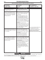
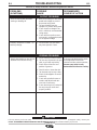
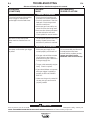
Troubleshooting..............................................................................................Section E
How to Use Troubleshooting Guide.......................................................................E-1
Troubleshooting Guide ............................................................................E-2 thru E-4
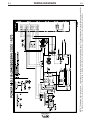
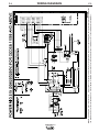
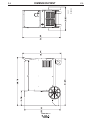
Wiring Diagram and Dimension Print............................................................Section F
Parts Manual....................................................................................................Appendix
POWER MIG 215 ..............................................................................................P-487
Magnum 250L Gun ....................................................................................P-202-H.2
POWER MIG 215

A-1
A-1
INSTALLATION
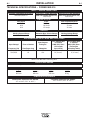
75°C Copper Wire 75°C Copper Wire
Input Ampere in Conduit in Conduit
Input Voltage/ Fuse or Breaker Rating On AWG (IEC) Sizes AWG (IEC) Sizes
(For lengths (For lengths
Frequency (Hz) Size (Super Lag) Nameplate up to 100 ft.) exceeding 100 ft.)
208/50/60 60 45A 10 (6 mm
2
) 8 (10 mm
2
)
230/50/60 60 41A 10 (6 mm
2
) 8 (10 mm
2
)
NOTE: Use #10 AWG Grounding Wire
TECHNICAL SPECIFICATIONS – POWER MIG 215
INPUT – SINGLE PHASE ONLY
RATED OUTPUT
OUTPUT
RECOMMENDED INPUT WIRE AND FUSE SIZES
Height Width Depth Weight
31.79 in 18.88 in 38.78 in 210 Ibs
808 mm 480 mm 985 mm 95 kg
PHYSICAL DIMENSIONS
Wire Speed 50 – 700 IPM (1.27 – 17.8 m/minute)
WIRE SPEED RANGE
Standard Voltage/Phase/Frequency
Input Current @ 170 Amp Rated Output Input Current @ 215 Amp Rated Output
208/230/1/50/60 Hz
(With 115V receptacle loaded to 15A) (With 115V receptacle loaded to 15A)
39/35 Amps 45/41 Amps
Duty Cycle Amps Volts at Rated Amperes
30% 215 Amps 22 Volts
40% 190 Amps 23 Volts
60% 170 Amps 24 Volts
Welding Current Range Maximum Open Circuit Voltage Welding Voltage Range
30 – 250Amps 35 Volts 13.5-24 Volts
POWER MIG 215
TEMPERATURE RANGES
STORAGE TEMPERATURE RANGE
-40°F to 185°F(-40°C to +40°C)
OPERATING TEMPERATURE RANGE
-4°F to 104°F(-20°C to +40°C)

A-2
A-2
INSTALLATION
Read entire installation section before starting
installation.
SAFETY PRECAUTIONS
POWER MIG 215
INPUT POWER, GROUNDING AND
CONNECTION DIAGRAMS
1. Before starting the installation, check with the local
power company if there is any question about
whether your power supply is adequate for the volt-
age, amperes, phase, and frequency specified on
the welder nameplate. Also be sure the planned
installation will meet the U.S. National Electrical
Code and local code requirements. This welder
may be operated from a single phase line or from
one phase of a two or three phase line.
2. Models that have multiple input voltages specified
on the nameplate (e.g. 208/230) are shipped con-
nected for the highest voltage. If the welder is to be
operated on lower voltage, it must be reconnected
according to the instructions in Figure A.1 for dual
voltage machines.
Make certain that the input power is electrically
disconnected before removing the screw on the
reconnect panel access cover.
------------------------------------------------------------------------
UNCRATING THE POWER MIG 215
Cut banding and lift off cardboard carton. Cut banding
holding the machine to the skid. Remove foam and
corrugated packing material. Untape accessories from
Gas Bottle Platform. Unscrew the two wood screws
(at the Gas Bottle Platform) holding the machine to
the skid. Roll the machine off the skid assembly.
LOCATION
Locate the welder in a dry location where there is free
circulation of clean air into the louvers in the back and
out the front. A location that minimizes the amount of
smoke and dirt drawn into the rear louvers reduces
the chance of dirt accumulation that can block air pas-
sages and cause overheating.
ELECTRIC SHOCK can kill.
• Only qualified personnel should
perform this installation.
• Only personnel that have read
and understood the POWER MIG
215 Operating Manual should
install and operate this equip-
ment.
• Machine must be grounded per
any national, local or other applic-
able electrical codes.
• The POWER MIG power switch is
to be in the OFF position when
installing work cable and gun and
when connecting other equip-
ment.
WARNING
WARNING
ELECTRIC SHOCK can kill.
• Do not touch electrically live parts such as
output terminals or internal wiring.
• All input power must be electrically dis-
connected before proceeding.
WARNING

3. The 208/230 volt 50/60 Hz model POWER MIG is
shipped with a 7 ft.(2.1m). input cable and plug
connected to the welder.
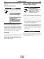
4. Using the instructions in Figure A.2, have a quali-
fied electrician connect a receptacle (Customer
Supplied) or cable to the input power lines and the
system ground per the U.S. National Electrical
Code and any applicable local codes. See
“Technical Specifications” at the beginning of this
chapter for proper wire sizes. For long runs over
100 feet, larger copper wires should be used. Fuse
the two hot lines with super lag type fuses as
shown in the following diagram. The center contact
in the receptacle is for the grounding connection. A
green wire in the input cable connects this contact
to the frame of the welder. This ensures proper
grounding of the welder frame when the welder
plug is inserted into a grounded receptacle.
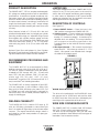
FIGURE A.2 — Receptacle Diagram
CONNECT TO A SYSTEM
GROUNDING WIRE. SEE
THE UNITED STATES
NATIONAL ELECTRICAL
CODE AND/OR LOCAL
CODES FOR OTHER
DETAILS AND MEANS FOR
PROPER GROUNDING.
CONNECT TO HOT WIRES
OF A THREE-WIRE, SINGLE
PHASE SYSTEM.
A-3 A-3
INSTALLATION
POWER MIG 215
50/60 HZ
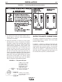
FIGURE A.1 — Dual Voltage Machine Input Connections
OUTPUT POLARITY CONNECTIONS
The welder, as shipped from the factory, is connected
for electrode positive (+) polarity. This is the normal
polarity for GMA welding.
If negative (–) polarity is required, interchange the
connection of the two cables located in the wire drive
compartment near the front panel. The electrode
cable, which is attached to the wire drive, is to be con-
nected to the negative (–) labeled terminal and the
work lead, which is attached to the work clamp, is to
be connected to the positive (+) labeled terminal.

GUN AND CABLE INSTALLATION
The Magnum 250L gun and cable provided with the
POWER MIG 215 is factory installed with a liner for
.035-.045" (0.9-1.2 mm) electrode and an .035" (0.9
mm) contact tip. Be sure that the contact tip, liner, and
drive rolls all match the size of the wire being used.
Turn the welder power switch off before installing
gun and cable.
1. Lay the cable out straight.
2. Unscrew knurled screw on the drive unit front end
(inside wire feed compartment) until tip of screw no
longer protrudes into gun opening as seen from
front of machine.
3. Insert the male end of gun cable into the Gun
Adapter casting through opening in front panel.
Make sure connector is fully inserted and tighten
knurled screw.
4. Connect the gun trigger connector from the gun
and cable to the mating receptacle inside the com-
partment located above the gun connection made
in item 3 above. Make sure that the keyways are
aligned, insert and tighten retaining ring.
SHIELDING GAS
(For Gas Metal Arc Welding Processes)
Customer must provide cylinder of appropriate type
shielding gas for the process being used.
A gas flow regulator, for Argon blend gas, and an inlet
gas hose are factory provided with the POWER MIG
215. When using 100% CO
2
an additional adapter will
be required to connect the regulator to the gas bottle.
Install shielding gas supply as follows:
1. Set gas cylinder on rear platform of POWER MIG
215. Hook chain in place to secure cylinder to rear
of welder.
WARNING
A-4
A-4
INSTALLATION
WARNING
2. Remove the cylinder cap. Inspect the cylinder
valves and regulator for damaged threads, dirt,
dust, oil or grease. Remove dust and dirt with a
clean cloth.
DO NOT ATTACH THE REGULATOR IF OIL,
GREASE OR DAMAGE IS PRESENT! Inform your
gas supplier of this condition. Oil or grease in the
presence of high pressure oxygen is explosive.
3. Stand to one side away from the outlet and open
the cylinder valve for an instant. This blows away
any dust or dirt which may have accumulated in the
valve outlet.
Be sure to keep your face away from the valve
outlet when “cracking” the valve.
4. Attach the flow regulator to the cylinder valve and
tighten the union nut(s) securely with a wrench.
NOTE: If connecting to 100% CO
2
cylinder, an
additional regulator adapter must be installed
between the regulator and cylinder valve. If adapter
is equipped with a plastic washer, be sure it is seat-
ed for connection to the CO
2
cylinder.
5. Attach one end of the inlet gas hose to the outlet
fitting of the flow regulator, the other end to the
POWER MIG 215 rear fitting, and tighten the union
nuts securely with a wrench.
6. Before opening the cylinder valve, turn the regula-
tor adjusting knob counterclockwise until the
adjusting spring pressure is released.
7. Standing to one side, open the cylinder valve slow-
ly a fraction of a turn. When the cylinder pressure
gauge pointer stops moving, open the valve fully.
Never stand directly in front of or behind the flow
regulator when opening the cylinder valve. Always
stand to one side.
___________________________________________
8. The flow regulator is adjustable. Adjust it to the flow
rate recommended for the procedure and process
being used before making the weld.
AUXILIARY POWER RECEPTACLES
(15 Amp 120 Volt Receptacle) The receptacles are UL
and CSA approved.
CYLINDER may explode if
damaged.
• Gas under pressure is explosive. Always
keep gas cylinders in an upright position
and always keep chained to undercarriage
or stationary support. See American
National Standard Z-49.1, “Safety in
Welding and Cutting” published by the
American Welding Society.
WARNING
POWER MIG 215
WARNING

B-1
B-1
OPERATION
Read entire Operation section before
operating the POWER MIG 215.
ELECTRIC SHOCK can kill.
• Do not touch electrically live
parts or electrode with skin or wet
clothing. Insulate yourself from
work and ground.
• Always wear dry insulating
gloves.
FUMES AND GASES can be
dangerous.
• Keep your head out of fumes.
• Use ventilation or exhaust to
remove fumes from breathing
zone.
WELDING SPARKS can
cause fire or explosion.
• Keep flammable material away.
• Do not weld on closed containers.
ARC RAYS can burn eyes
and skin.
• Wear eye, ear and body protec-
tion.
Observe all safety information throughout
this manual.
WARNING
POWER MIG 215

B-2 B-2
OPERATION
PRODUCT DESCRIPTION
The POWER MIG™ 215 is a complete semiautomatic
DC voltage arc welding machine built to meet NEMA
specifications. It combines a tapped transformer volt-
age power source with a constant speed wire feeder
to form a reliable robust performance welding system.
A simple control scheme, consisting of continuous full
range wire feed speed control, and 7 output voltage
tap selections provides versatility with ease of use and
accuracy.
Other features include a 2" (51 mm) O.D. wire reel
spindle with adjustable brake, an integral gas cylinder
mounting undercarriage, an adjustable Argon blend
flow regulator with cylinder pressure gauge and inlet
hose, a 15 ft. (3.6 m) Magnum 250L GMAW gun and
cable with fixed (flush) nozzle, a 7 ft. (2.1 m) power
cable with plug, and a 10 ft. (3.0 m) work cable with
clamp.
Optional Spool Gun and Adapter kit, Dual Cylinder
Mounting kit and Aluminum Feeding Kit for push feed-
ing with standard built in feeder are also available.
RECOMMENDED PROCESSES AND
EQUIPMENT
The POWER MIG 215 is recommended for GMA
welding processes using 10 to 44 lb (4.5 to 20 kg) 2"
(51 mm) I.D. spools or Readi-Reel
®
coils (with option-
al adapter) of .025" through .045" (0.6 – 1.2 mm) solid
steel, .035" (0.9 mm) stainless, 3/64" (1.2 mm) alu-
minum and .035 (0.9 mm), .045" (1.2 mm)
Outershield
®
; as well as .035" (0.9 mm) and .045" (1.2
mm) Innershield
®
self-shielding electrodes.
The POWER MIG is factory equipped to feed .035"
(0.9 mm) electrodes. It also includes a 200A, 60%
duty cycle (or 250A, 40% duty cycle) rated, 15 ft. (3.6
m) GMAW gun and cable assembly equipped for
these wire sizes. Use of GMAW processes requires a
supply of shielding gas.
WELDING CAPABILITY
The POWER MIG 215 is rated at 215 amps @ 22
volts, at a 30% duty cycle based on a ten minute cycle
time. It is capable of higher duty cycles at lower output
currents. The tapped transformer design makes it
well suited for use with most portable or in-plant gen-
erating systems.
LIMITATIONS
The output voltage/current of the POWER MIG 215 is
subject to vary if the input power to the machine
varies, due to its tapped transformer power topology.
In some cases an adjustment of WFS preset and/or
voltage tap selection may be required to accommo-
date a significant drift in input power.
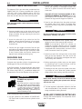
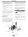
DESCRIPTION OF CONTROLS
See Figure B.1
1. Power ON/OFF Switch — Place the lever in the
"ON" position to energize the POWER MIG 215.
2. Voltage Control — Seven voltage tap selections
are provided Labeled "A" (minimum voltage)
through "G" (maximum voltage). It should only be
adjusted when not welding. The control selection
can be preset to the setting specified on the
Procedure Decal on the inside of the wire compart-
ment door.
3. Wire Speed Control — This controls the wire feed
speed from 50 – 700 inches per minute (1.2 – 17.8
m/min). Wire speed is not affected when changes
are made in the voltage control.
FIGURE B.1
WIRE DRIVE ROLL
The drive rolls installed with the POWER MIG have
two grooves one for .035(0.9mm) wire and the other
for .045(1.2mm) wire. Drive roll size is indicated by the
stenciling on the exposed side of the drive roll.
WIRE SIZE CONVERSION PARTS
The POWER MIG 215 is rated to feed .025 through
.045" (0.6-1.2 mm) solid or cored electrode sizes.
The drive roll kits and Magnum 250L gun and cable
parts are available to feed different sizes and types of
electrodes. See Accessories section.
POWER MIG 215
33
22
11

B-3 B-3
OPERATION
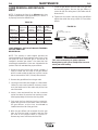
PROCEDURE FOR CHANGING
DRIVE AND IDLE ROLL SETS
1. Turn off the power source.
2. Release the pressure on the idle roll by swinging
the adjustable pressure arm down toward the back
of the machine. Lift the cast idle roll assembly and
allow it to sit in an upright position..
3. Remove the outside wire guide retaining plate by
loosening the two large knurled screws.
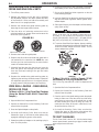
4. Twist the drive roll retaining mechanism to the
unlocked position as shown below and remove the
drive rolls. (See FigureB.2)
5. Remove the inside wire guide plate.
6. Replace the drive rolls and inside wire guide with a
set marked for the new wire size. NOTE: Be sure
that the gun liner and contact tip are also sized to
match the selected wire size.
7. Manually feed the wire from the wire reel, over the
drive roll groove and through the wire guide and
then into the brass bushing of the gun and cable
assembly.
8. Replace the outside wire guide retaining plate by
tightening the two large knurled screws. Reposition
the adjustable pressure arm to its original position
to apply pressure. Adjust pressure as necessary.
WIRE REEL LOADING - READI-REELS,
SPOOLS OR COILS
To Mount a 30 Lb. (14 kg) Readi-Reel Package
(Using the Molded Plastic K363-P Readi-Reel
Adapter:)
1. Open the Wire Drive Compartment Door
2. Depress the Release Bar on the Retaining Collar and
remove it from the spindle.
3. Place the Optional Adapter on the spindle
4. Re-install the Retaining Collar. Make sure that the
Release Bar “pops up” and that the collar retainers fully
engage the retaining ring groove on the spindle.
5. Rotate the spindle and adapter so the retaining spring is
at the 12 o'clock position.
6. Position the Readi-Reel so that it will rotate in a direction
when feeding so as to be de- reeled from top of the coil.
7. Set one of the Readi-Reel inside cage wires on the slot
in the retaining spring tab.
8. Lower the Readi-Reel to depress the retaining spring and
align the other inside cage wires with the grooves in the
molded adapter.
9. Slide cage all the way onto the adapter until the retaining
spring "pops up" fully.
CHECK TO BE SURE THE RETAINING SPRING HAS FULLY
RETURNED TO THE LOCKING POSITION AND HAS SECURELY
LOCKED THE READI-REEL CAGE IN PLACE. RETAINING SPRING
MUST REST ON THE CAGE, NOT THE WELDING ELECTRODE.
-----------------------------------------------------------------------------------------------
10. To remove Readi-Reel from Adapter, depress retaining
spring tab with thumb while pulling the Readi-Reel cage
from the molded adapter with both hands. Do not
remove adapter from spindle.
FIGURE B.1
To Mount 10 to 44 Lb. (4.5-20 kg) Spools (12"/300
mm Diameter) or 14Lb.(6 Kg) Innershield Coils:
(For 13-14 lb. (6 Kg) Innershield coils, a K435 Coil Adapter must be
used).
1
. Open the Wire Drive Compartment Door
2. Depress the Release Bar on the Retaining Collar and
remove it from the spindle.
3. Place the spool on the spindle making certain the spindle
brake pin enters one of the holes in the back side of the
spool (Note: an arrow mark on the spindle lines up with
the brake holding pin to assist in lining up a hole). Be
certain the wire comes off the reel in a direction so as to
de-reel from the top of the coil.
4. Re-install the Retaining Collar. Make sure that the
Release Bar “pops up” and that the collar retainers fully
engage the retaining ring groove on the spindle.
TO START THE WELDER
Turn the “Power Switch” switch to “ON”. With the desired voltage
and wire speed selected, operate the gun trigger for welder output
and to energize the wire feed motor.
CAUTION
POWER MIG 215
LOCKED POSITION
UNLOCKED POSITION
FIGURE B.2

B-4 B-4
OPERATION
FEEDING WIRE ELECTRODE
When triggering, the electrode and
drive mechanism are electrically “hot”
relative to work and ground and
remain “hot” several seconds after
the gun trigger is released.
------------------------------------------------------------------------
NOTE: Check that drive rolls, guide plates and gun
parts are proper for the wire size and type being used.
Refer to Table C.1 in Accessories section.
1. Turn the Readi-Reel or spool until the free end of
the electrode is accessible.
2. While securely holding the electrode, cut off the
bent end and straighten the first six inches. (If the
electrode is not properly straightened, it may not
feed properly through the wire drive system).
3. Release the pressure on the idle roll by swinging
the adjustable pressure arm down toward the back
of the machine. Lift the cast idle roll assembly and
allow it to sit in an upright position. Leave the outer
wire guide plate installed. Manually feed the wire
through the incoming guide bushing and through
the guide plates (over the drive roll groove). Push a
sufficient wire length to assure that the wire has fed
into the gun and cable assembly without restriction.
Reposition the adjustable pressure arm to its origi-
nal position to apply pressure to the wire.
4. Press gun trigger to feed the electrode wire through
the gun.
IDLE ROLL PRESSURE SETTING
ELECTRIC SHOCK can kill.
• Turn the input power OFF at the weld-
ing power source before installation or
changing drive rolls and/or guides.
• Do not touch electrically live parts.
• When inching with the gun trigger, electrode
and drive mechanism are "hot" to work and
ground and could remain energized several sec-
onds after the gun trigger is released.
• Only qualified personnel should perform mainte-
nance work.
------------------------------------------------------------------------
The pressure arm controls the amount of force the drive
rolls exert on the wire. Proper adjustment of both pres-
sure arm gives the best welding performance. For best
results, set both pressure arms to the same value.
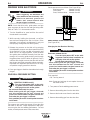
Set the pressure arm as follows (See Figure B.2a):
Aluminum wires between 1 and 3
Cored wires between 3 and 4
Steel, Stainless wires between 4 and 6
WIRE DRIVE CONFIGURATION
(See Figure B.2b)
Changing the Gun Receiver Bushing
ELECTRIC SHOCK can kill.
• Turn the input power OFF at the weld-
ing power source before installation or
changing drive rolls and/or guides.
• Do not touch electrically live parts.
• When inching with the gun trigger, electrode
and drive mechanism are "hot" to work and
ground and could remain energized several sec-
onds after the gun trigger is released.
• Only qualified personnel should perform mainte-
nance work.
-----------------------------------------------------------------------
Tools required:
• 1/4" hex key wrench.
Note: Some gun bushings do not require the use of
the thumb screw.
1. Turn power off at the welding power source.
2. Remove the welding wire from the wire drive.
3. Remove the thumb screw from the wire drive.
4. Remove the welding gun from the wire drive.
WARNING
WARNING
WARNING
POWER MIG 215
ALUMINUM
OUTERSHIELD
METALSHIELD
INNERSHIELD
STEEL
S
TAINLESS
CORED WIRES
SOLID WIRES
6
1
3
2
5
4

B-5 B-5
OPERATION
3. Press the trigger to feed the wire electrode through
the gun and cable. For solid wire cut the electrode
within approximately 3/8" (10 mm) of the end of the
contact tip [3/4" (20 mm) for Outershield
®
].
4. When welding with gas, turn on the gas supply and
set the required flow rate (typically 25-35 CFH; 12-
16 liters/min).
5. Connect work cable to metal to be welded. Work
clamp must make good electrical contact to the
work. The work must also be grounded as stated in
“Arc Welding Safety Precautions”.
• When using an open arc process, it
is necessary to use correct eye,
head, and body protection.
-----------------------------------------------------------------------
6. Position electrode over joint. End of electrode may
be lightly touching the work.
7. Lower welding helmet, close gun trigger, and
begin welding. Hold the gun so the contact tip to
work distance is about 3/8" (10 mm) [3/4" (20 mm)
for Outershield
®
].
8. To stop welding, release the gun trigger and then
pull the gun away from the work after the arc goes
out.
POWER MIG 215
GUN RECEIVER BUSHING
LOOSEN TIGHTEN
THUMB SCREW
OUTER WIRE GUIDE
SOCKET HEAD
CAP SCREW
CONNECTOR BLOCK
WARNING
5. Loosen the socket head cap screw that holds the
connector bar against the gun bushing.
Important: Do not attempt to completely
remove the socket head cap screw.
6. Remove the outer wire guide, and push the gun
bushing out of the wire drive. Because of the pre-
cision fit, light tapping may be required to remove
the gun bushing.
7. Disconnect the shielding gas hose from the gun
bushing, if required.
8. Connect the shielding gas hose to the new gun
bushing, if required.
9. Rotate the gun bushing until the thumb screw hole
aligns with the thumb screw hole in the feed plate.
Slide the gun receiver bushing into the wire drive
and verify the thumb screw holes are aligned.
10. Tighten the socket head cap screw.
11. Insert the welding gun into the gun bushing and
tighten the thumb screw.
MAKING A WELD
1. Check that the electrode polarity is correct for the
process being used, then turn the power switch ON.
2. Set desired arc voltage tap and wire speed for the
particular electrode wire, material type and thick-
ness, and gas (for MIG and Outershield
®
) being
used. Use the Application Chart on the door inside
the wire compartment as a quick reference for
some common welding procedures.
Figure B.2b

B-6 B-6
OPERATION
9. When no more welding is to be done, close valve
on gas cylinder (if used), momentarily operate gun
trigger to release gas pressure, and turn off
POWER MIG 215.
NOTE: When using Innershield electrode, the gas
nozzle may be removed from the insulation on
the end of the gun and replaced with the gas-
less nozzle. This will give improved visibility
and eliminate the possibility of the gas nozzle
overheating.
AVOIDING WIRE FEEDING
PROBLEMS
Wire feeding problems can be avoided by observing
the following gun handling procedures:
1. Do not kink or pull cable around sharp corners.
2. Keep the gun cable as straight as possible when
welding or loading electrode through cable.
3. Do not allow dolly wheels or trucks to run over
cables.
4. Keep cable clean by following maintenance instruc-
tions.
5. Use only clean, rust-free electrode. The Lincoln
electrodes have proper surface lubrication.
6. Replace contact tip when the arc starts to become
unstable or the contact tip end is fused or
deformed.
7. Keep wire reel spindle brake tension to minimum
required to prevent excess reel over-travel which
may cause wire “loop-offs” from coil.
8. Use proper drive rolls and wire drive idle roll pres-
sure for wire size and type being used.
FAN CONTROL
The fan is designed to come on when input power is
applied to the POWER MIG 215 and go off when
power is removed.
INPUT LINE VOLTAGE VARIATIONS
High Line Voltage — Higher than rated input voltage
will result in output voltages higher than normal for a
given tap setting. If your input line is high, you may
want to select a lower voltage tap than given on the
recommended procedure chart.
Low Line Voltage — You may not be able to get
maximum output from the machine if the line voltage
is less than rated input. The unit will continue to weld,
but the output may be less than normal for a given tap
setting. If your input line is low, you may want to select
a higher voltage tap than given on the recommended
procedure chart.
WIRE FEED OVERLOAD
PROTECTION
The POWER MIG has solid state overload protection
of the wire drive motor. If the motor becomes over-
loaded, the protection circuitry turns off the wire feed
speed and gas solenoid. Check for proper size tip,
liner, and drive rolls, for any obstructions or bends in
the gun cable, and any other factors that would
impede the wire feeding. to resume welding, simply
pull the trigger. There is no circuit breaker to reset, as
the protection is done with reliable solid state electron-
ics.
WELDING THERMAL OVERLOAD
PROTECTION
The POWER MIG 215 has built-in protective ther-
mostats that respond to excessive temperature. They
open the wire feed and welder output circuits if the
machine exceeds the maximum safe operating tem-
perature because of a frequent overload, or high
ambient temperature plus overload. The thermostats
automatically reset when the temperature reaches a
safe operating level and welding and feeding are
allowed again, when gun is retriggered.
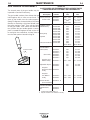
Wire Feed Speed/Voltage Tap Settings
Wire Dia. Gas Type Wire Type
Polarity 18 gage 16 gage14 gage 12 gage10gage 3/16 1/4 5/16 3/8 1/2
Outershield
1" CTWD
†
.035 75Ar/25CO
2
OS71M DC+
250/D 300/E 350/F 500/G *500/G
.035 100%CO
2
OS71M DC+
300/E 350/F 500/G
.045 75Ar/25CO
2
OS71M DC+
200/E 225/F 250/G 250/G *250/G
Innershield
5/8" CTWD
†
.035 NoneReqʼd NR-211MP DC-
50/B 70/B 80/B 90/C 100/C
.045 NoneReqʼd NR-211MP DC-
50/B 70/C 90/C 110/D
**130/E
.045 NoneReqʼd NR212 DC-
40/B 50/B 60/B 65/C 70/C 90/C 110/D
*130/E *150/E *150/E
POWER MIG 215
PROCEDURE CHART
†
Contact Tip to Work Distance
* Note- Requires Multiple Pass
**.035 & .045 NR-211 MP are only recommended for a maximum steel thickness of 5/16"

C-1 C-1
ACCESSORIES
DRIVE ROLL KITS
Refer to Table C.1 for various drive roll kits that are
available for the POWER MIG 215.The item in Bold is
supplied standard with the POWER MIG 215.
TABLE C.1
3/64" (1.2 mm) ALUMINUM
FEEDING KIT (K1703-1)
This kit helps push feeding aluminum through stan-
dard machine feeder and gun. It provides gun and
wire drive conversion parts to weld with 3/64" (1.2
mm) aluminum wire. 5356 alloy aluminum wire is rec-
ommended for best push feeding performance.
Kit includes drive rolls and wire guide plate for the
wire drive, liner and two contact tips for the gun, along
with installation instructions.
READI-REEL ADAPTER (K363P)
The K363P Readi-Reel Adapter mounts to the 2" spin-
dle. It is needed to mount the 22-30 lb. Readi-Reels.
DUAL CYLINDER MOUNTING KIT
(K1702-1)
Permits stable side-by-side mounting of two full size
228.6mm dia x 1.524m high(9" dia. x 5' high) gas
cylinders with “no lift” loading. Simple installation and
easy instructions provided. Includes upper and lower
cylinder supports, wheel axles and mounting hard-
ware.
SMALL SPOOL SPINDLE ADAPTER
(K468)
The K468 spindle adapter allows the use of 8" diamter
small spools.
ALTERNATIVE MAGNUM GMAW
GUN AND CABLE ASSEMBLIES
The following Magnum 250L gun and cable assem-
blies are separately available for use with the POWER
MIG 215. Each is rated 250 amps 40% duty cycle and
is equipped with the integrated connector, twist-lock
trigger connector, fixed nozzle and insulator, and
includes a liner, diffuser, and contact tips for the wire
sizes specified:
MAGNUM GUN CONNECTION KIT
(Optional K466-6)
Using the optional K466-6 Magnum Connection kit for
the POWER MIG permits use of standard Magnum
200, 300 or 400 gun and cable assemblies.
SPOOL GUN AND ADAPTER KIT
(K1809-1)
The K1809-1includes the Magnum 250SG Spool gun
and the adapter kit for connecting the spool gun to the
Power MIG 215.
The Adapter Kit provides toggle switch selection
between the machineʼs use with its feeder gun or the
spool gun for same polarity welding with different wire
and gas processes.
The kit includes a spool gun adapter module assem-
bly with a single connecting plug and trigger switch, a
rear gas inlet, fitting hose, solenoid valve assembly,
and mounting hardware with installation and operation
instructions.
• Unplug or Disconnect all input power
from the POWER MIG 215 before
installing the Spool Gun and Kit.
------------------------------------------------------------------------
Wire Size Drive Roll Kit
.023”-.030” (0.6-0.8 mm)
KP1696-030S
.035” (0.9 mm) KP1696-035S
Solid
.045” (1.2 mm) KP1696-045S
Steel
.035-.045 (0.9-1.2mm) KP1696-1
.040 (1.01) KP1696-2
Cored
.035” (0.9 mm) KP1697-035C
.045” (1.2 mm) KP1697-045C
Aluminum
3/64” (1.2 mm) KP1695-3/64A
English Wire Metric Wire
Length Part No. Size Size
10' (3.0 m) K533-1
12' (3.6 m) K533-7 .035 – .045" 0.9 – 1.2 mm
15' (4.5 m) K533-3
WARNING
POWER MIG 215

MAKING A WELD WITH THE SPOOL GUN
ADAPTER KIT AND SPOOL GUN
INSTALLED
In either toggle switch position, closing either gun
trigger will cause the electrode of both guns to be
electrically “HOT”. Be sure unused gun is posi-
tioned so electrode or tip will not contact metal
case or other metal common to work.
------------------------------------------------------------------------
1. Setting spool gun selector switch to the “Normal”
position and pulling the trigger for the built-in feed-
er gun.
• Disables spool gun operation and spool gun
gas solenoid valve.
• Closing feeder gun trigger starts feeder gun
welding and makes both electrodes electrically
“HOT”.
2. Setting spool gun selector switch to the Spool Gun
Position and pulling SPOOL GUN Trigger.
• Disables built-in feeder gun operation and
machine gas solenoid valve.
• Enables spool gun operation and spool gun gas
solenoid valve.
• Closing spool gun trigger starts spool gun weld-
ing and makes both electrodes electrically
“HOT”.
3. Operation with POWER MIG 215:
• Turn the POWER MIG-215 input power ON.
• Adjusting the voltage tap control will increase or
decrease your welding voltage.
• Adjusting the wire speed control on the spool
gun will increase or decrease the spool gun
wire feed speed. NOTE: Adjusting the wire feed
speed control on the Power Mig Panel has no
affect on the spool gunʼs wire feed speed.
4. Refer to the procedure decal on the Power Mig for
initial aluminum settings. Make a test weld to deter-
mine the final settings.
5. To return to normal POWER MIG 215 welding,
release the spool gun trigger set spool gun selector
switch to normal and reset feeder gun voltage pro-
cedure setting if necessary.
C-2 C-2
ACCESSORIES
CAUTION
POWER MIG 215
La page est en cours de chargement...
La page est en cours de chargement...
La page est en cours de chargement...
La page est en cours de chargement...
La page est en cours de chargement...
La page est en cours de chargement...
La page est en cours de chargement...
La page est en cours de chargement...
La page est en cours de chargement...
La page est en cours de chargement...
La page est en cours de chargement...
La page est en cours de chargement...
La page est en cours de chargement...
La page est en cours de chargement...
La page est en cours de chargement...
-
 1
1
-
 2
2
-
 3
3
-
 4
4
-
 5
5
-
 6
6
-
 7
7
-
 8
8
-
 9
9
-
 10
10
-
 11
11
-
 12
12
-
 13
13
-
 14
14
-
 15
15
-
 16
16
-
 17
17
-
 18
18
-
 19
19
-
 20
20
-
 21
21
-
 22
22
-
 23
23
-
 24
24
-
 25
25
-
 26
26
-
 27
27
-
 28
28
-
 29
29
-
 30
30
-
 31
31
-
 32
32
-
 33
33
-
 34
34
-
 35
35


Lincoln Electric 215 Manuel utilisateur
- Catégorie
- Système de soudage
- Taper
- Manuel utilisateur
- Ce manuel convient également à
dans d''autres langues
- English: Lincoln Electric 215 User manual
Documents connexes
-
Lincoln Electric K1170 Le manuel du propriétaire
-
Lincoln Electric POWER MIG 256 Manuel utilisateur
-
-
-
-
Lincoln Electric IM756-A Manuel utilisateur
-
-
-
-