Panasonic DW7000U-K - WXGA DLP Projector Manuel utilisateur
- Catégorie
- Projecteurs de données
- Taper
- Manuel utilisateur

DLP
TM
Based Projector Commercial Use
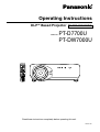
Operating Instructions
Read these instructions completely before operating this unit.
TQBJ 0146-1
POWER
ON OFF
RGB
1
RGB
2
AUX
MENU
STD
LENS
OSD
1
4
7
2
5
8
3
6
9
0
NEXT
USER
LIGHT
ID ALL
ASPECT
ID SET
Projector
Computer
Numetric
BRIGHT
CONTRAST
ON SCREEN
SYSTEM
SEL
FUNC
1
D.ZOOM
ENTER
PAG E UP
PAG E DOWN
VIDEO
SHUT
S-
VIDEO
FREEZE
SHUTTER
AUTO
SETUP
LASER ON/OFF
Model No.
PT-D7700U
PT-DW7000U

2
Dear Panasonic Customer:
This instruction booklet provides all the necessary operating information that you might require. We hope it will help
you to get the most performance out of your new product, and that you will be pleased with your Panasonic DLP
TM
based projector.
The serial number of your product may be found on its back. You should note it in the space provided below and
retain this booklet in case service is required.
Model number: PT-D7700U / PT-DW7000U
Serial number:
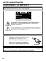
IMPORTANT SAFETY NOTICE
WARNING: TO REDUCE THE RISK OF FIRE OR ELECTRIC SHOCK, DO NOT EXPOSE
THIS PRODUCT TO RAIN OR MOISTURE.
WARNING
RISK OF ELECTRIC
SHOCK. DO NOT OPEN
MISE EN GARDE-
WARNUNG-
RISQUE DE CHOC ÉLECTRIQUE.
NE PAS OUVRIR.
ZUR VERMEIDUNG EINES ELEKTRISCHEN
SCHLAGES GERÄT NICHT ÖFFNEN.
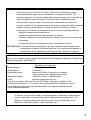
The lightning flash with arrowhead symbol, within an equilateral triangle, is intended to alert
the user to the presence of uninsulated “dangerous voltage” within the Product's enclosure
that may be of sufficient magnitude to constitute a risk of electric shock to persons.
The exclamation point within an equilateral triangle is intended to alert the
user to the presence of important operating and maintenance (servicing)
instructions in the literature accompanying the product.
CAUTION: This equipment is equipped with a three-pin
grounding-type power plug. Do not remove the
grounding pin on the power plug. This plug will
only fit a grounding-type power outlet. This is a
safety feature. If you are unable to insert the plug
into the outlet, contact an electrician. Do not
defeat the purpose of the grounding plug.
Do not remove

3
WARNING:
This equipment has been tested and found to comply with the limits for a Class B digital
device, pursuant to part 15 of the FCC Rules. These limits are designed to provide
reasonable protection against harmful interference in a residential installation. This
equipment generates, uses and can radiate radio frequency energy and, if not installed and
used in accordance with the instructions, may cause harmful interference to radio
communications. However, there is no guarantee that interference will not occur in a
particular installation. If this equipment does cause harmful interference to radio or television
reception, which can be determined by turning the equipment off and on, the user is
encouraged to try to correct the interference by one or more of the following measures:
– Reorient or relocate the receiving antenna.
– Increase the separation between the equipment and receiver.
– Connect the equipment into an outlet on a circuit different from that to which the receiver
is connected.
–
Consult the dealer or an experienced radio/TV technician for help.
FCC CAUTION: To assure continued compliance, use only shielded interface cables when
connecting to computer or peripheral devices. Any unauthorized changes or
modifications to this equipment could void the user’s authority to operate.
WARNING:
Not for use in a computer room as defined in the Standard for the Protection of Electronic Computer/Data
Processing Equipment, ANSI/NFPA 75.
NOTICE: This product has a High Intensity Discharge (HID) lamp that contains a small amount
of mercury. It also contains lead in some components. Disposal of these materials
may be regulated in your community due to environmental considerations. For
disposal or recycling information please contact your local authorities, or the
Electronics Industries Alliance: <http://www.eiae.org.>
Declaration of Conformity
Model Number: PT-D7700U / PT-DW7000U
Trade Name: Panasonic
Responsible Party: Matsushita Electric Corporation of America
One Panasonic Way, Secaucus, NJ 07094
Telephone Number: 1-800-524-1448 or 1-800-526-6610
Email: [email protected]
This device complies with Part 15 of the FCC Rules. Operation is subject to the
following two conditions: (1) This device may not cause harmful interference, and (2)
this device must accept any interference receiver, including interference that may
cause undesired operation.

4
IMPORTANT SAFETY NOTICE ..................................2
Precautions with regard to safety ............................5
Accessories ................................................................7
Precautions on handling ...........................................8
Examples of system expansion................................9
Name and function of parts.....................................10
Remote control ................................................................10
Front and side of the projector ........................................12
Rear view of the main unit...............................................13
Controls on rear panel.....................................................13
Side-mounted connection terminals ................................14
Using the remote control unit .................................15
Loading dry cells .............................................................15
Effective range of remote control operation ....................15
Setting projector ID number to remote control ................16
Using the remote control as a PC mouse........................17
Using a wired remote control...........................................17
Installation ................................................................18
Adjusting the leveling feet ...............................................18
Projection scheme...........................................................18
Installation geometry .......................................................18
Projection distances by the type of projection lenses (optional)
..19
Connection ...............................................................24
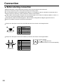
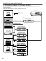
Before starting connection...............................................24
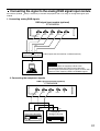
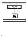
Example of connecting with VIDEO devices ...................25
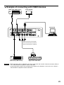
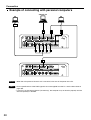
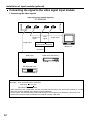
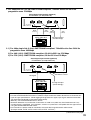
Example of connecting with personal computers ............26
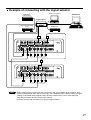
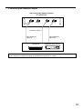
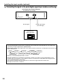
Example of connecting with the signal selector...............27
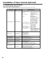
Installation of input module (optional)...................28
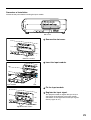
Installing the input module...............................................28
Connecting signals to the input module ..........................30
Connecting the signal to the analog RGB signal input module
..31
Connecting the signal to the video signal input module ..32
Connecting the signal to the serial digital signal input module
..34
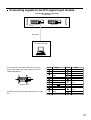
Connecting signals to the DVI signal input module .........37
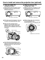
How to install and remove the projection lens (optional)
..........38
How to install the projection lens.....................................38
How to remove the projection lens ..................................38
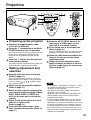
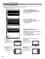
Projection..................................................................39
Powering up the projector ...............................................39
Making adjustment and selection ....................................39
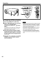
Powering off the projector ...............................................40
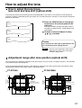
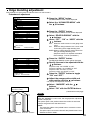
How to adjust the lens .............................................41
How to adjust the lens focus, lens zoom and lens shift (optical shift)
..41
Adjustment range after lens position (optical shift)..........41
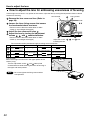
How to adjust the lens for addressing unevenness of focusing
..42
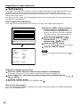
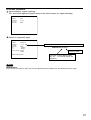
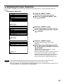
Automatic adjustment (AUTO SETUP)...................43
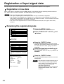
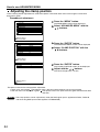
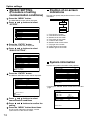
Registration of input signal data ............................44
Registration of new data..................................................44
Renaming the registered signals.....................................44
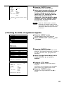
Clearing the data of registered signals
...............................
45
Sub memory ....................................................................46
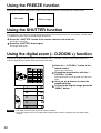
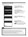
Using the FREEZE function ....................................48
Using the SHUTTER function..................................48
Using the digital zoom (– D.ZOOM +) function ...............
48
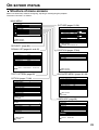
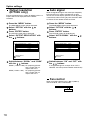
On-screen menus.....................................................49
Structure of menu screens ..............................................49
Basic operations on menu screen ...................................50
Returning to the previous screen ....................................50
Menu items shown in gray characters.............................50
Menu items setting ..........................................................50
Resetting to the factory default........................................50
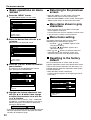
Adjusting the picture ...............................................51
Switching the picture mode .............................................51
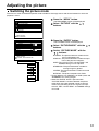
Adjusting Contrast / Bright / Color / Tint ..........................52
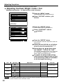
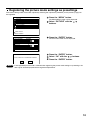
Registering the picture mode settings as presettings......53
DYNAMIC IRIS setting ....................................................54
Adjusting the color temperature ......................................55
Sharpness / Gamma / Noise reduction ...........................56
To display pictures complying with the sRGB standard ..56
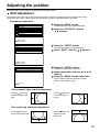
Adjusting the position .............................................57
Shift adjustment...............................................................57
Size adjustment...............................................................58
Clock phase adjustment ..................................................59
Keystone distortion correction .........................................60
How to use ADVANCED MENU ...............................61
DIGITAL CINEMA REALITY ...........................................61
FORMAT (To input BETACAM with YCbCr 480i) ...........61
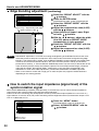
Blanking adjustment ........................................................62
Adjusting the input resolution ..........................................63
Adjusting the clamp position............................................64
Edge blending adjustment...............................................65
How to switch the input impedance (signal level)
of the synchronization signal ...........................................66
Raster position ................................................................67
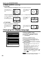
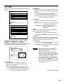
Changing the display language ..............................68
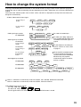
How to change the system format..........................69
How to use RGB REALITY mode ............................70
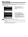
Option settings.........................................................71
ID number setting ............................................................71
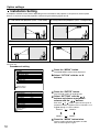
Installation Setting ...........................................................72
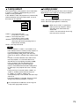
Lamp select .....................................................................73
Lamp power.....................................................................73
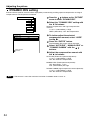
RS232C SETTING (Procedure of setting communication conditions)
..74
Position of on-screen indications.....................................74
System information..........................................................74
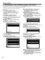
Adjusting color matching .................................................75
Adjusting the color matching using a colorimeter............76
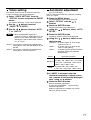
Video setting....................................................................77
Automatic adjustment......................................................77
Output resolution (D7700U only).....................................78
Auto signal.......................................................................78
Fan control ......................................................................78
P IN P ..............................................................................79
Setting FUNC1 ................................................................80
Password.........................................................................80
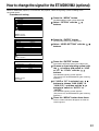
How to change the signal for the
ET-MD95VM2 (optional) ...........................................81
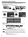
Using the serial terminals .......................................82
Examples of connection .................................................82
Pin assignments and signal names.................................82
Communication conditions (Factory setting) ...................82
Basic format ....................................................................82
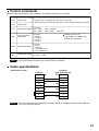
Control commands ..........................................................83
Cable specifications ........................................................83
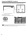
Using the REMOTE 2 terminal ................................84
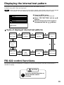
Displaying the internal test pattern ........................85
Cycle of displayed internal test patterns..........................85
RS-422 control functions.........................................85
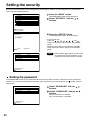
Setting the security..................................................86
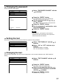
Setting the password.......................................................86
Changing the password...................................................87
Setting the text ................................................................87
Changing the text ............................................................87
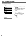
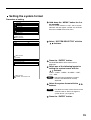
How to use CP OPTION ...........................................88
Setting the on-screen indication function ........................88
Setting the system format................................................89
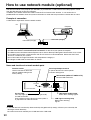
How to use network module (optional) ..................90
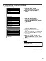
Initial setting of network module ......................................91
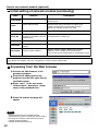
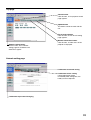
Accessing from the Web browser....................................92
Returning the network module setting back to the factory setting
..97
Indication of monitor lamp ......................................98
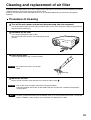
Cleaning and replacement of air filter....................99
Procedure of cleaning .....................................................99
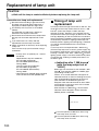
Replacement of lamp unit .....................................100
Timing of lamp unit replacement ...................................100
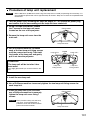
Procedure of lamp unit replacement .............................101
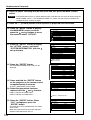
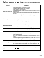
Before asking for service ......................................103
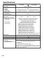
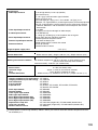
Specifications.........................................................104
Appendix.................................................................106
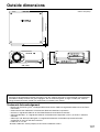
Outside dimensions...............................................107
Français Information..............................................108
Contents

5
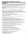
Precautions with regard to safety
WARNING
If a problem occurs (such as no image) or if you notice smoke or a strange smell coming
from the projector, turn off the power and disconnect the power cord from the wall outlet.
• Do not continue to use the projector in such cases, otherwise fire or electric shocks could result.
• Check that no more smoke is coming out, and then contact an Authorized Service Center for repairs.
• Do not attempt to repair the projector yourself, as this can be dangerous.
Do not install this projector in a place which is not strong enough to take the full weight
of the projector.
• If the installation location is not strong enough, it may fall down or tip over, and severe injury or damage could
result.
• Installation work (such as ceiling suspension) should only be carried out by a qualified technician.
• If installation is not carried out correctly, there is the danger that injury or electric shocks may occur.
If foreign objects or water get inside the projector, or if the projector is dropped or the
cabinet is broken, turn off the power and disconnect the power cord from the wall outlet.
• Continued use of the projector in this condition may result in fire or electric shocks.
• Contact an Authorized Service Center for repairs.
Do not cover the air filter, the air inlet and exhaust vents.
• Doing so may cause the projector to overheat, which can cause fire or damage to the projector.
Do not overload the wall outlet.
• If the power supply is overloaded (for example, by using too many adapters), overheating may occur and fire
may result.
Do not remove the cover or modify it in any way.
• High voltages which can cause fire or electric shocks are present inside the projector.
• For any inspection, adjustment and repair work, please contact an Authorized Service Center.
Clean the power cord plug regularly to prevent it from becoming covered in dust.
• If dust builds up on the power cord plug, the resulting humidity can damage the insulation, which could result in
fire. Pull the power cord out from the wall outlet and wipe it with a dry cloth.
• If not using the projector for an extended period of time, pull the power cord plug out from the wall outlet.
Do not do anything that might damage the power cord or the power cord plug.
• Do not damage the power cord, make any modifications to it, place it near any hot objects, bend it excessively,
twist it, pull it, place heavy objects on top of it or wrap it into a bundle.
• If the power cord is used while damaged, electric Shocks, short-circuits or fire may result.
• Ask an Authorized Service Center to carry out any repairs to the power cord that might be necessary.
Do not handle the power cord plug with wet hands.
• Failure to observe this may result in electric shocks.
Insert the power cord plug securely into the wall outlet.
• If the plug is not inserted correctly, electric shocks or overheating could result.
• Do not use plugs which are damaged or wall outlets which are coming loose from the wall.
Do not place the projector on top of surfaces which are unstable.
• If the projector is placed on top of a surface which is sloped or unstable, it may fall down or tip over, and injury or
damage could result.
Do not place the projector into water or let it become wet.
• Failure to observe this may result in fire or electric shocks.
Do not disassemble the lamp unit.
• If the lamp section breaks, it may cause injury.

6
Precautions with regard to safety
Do not place liquid containers on top of the projector.
• If water spills onto the projector or gets inside it, fire or electric shocks could result.
• If any water gets inside the projector, contact an Authorized Service Center.
Do not insert any foreign objects into the projector.
• Do not insert any metal objects or flammable objects into the projector or drop them onto the projector, as doing
so can result in fire or electric shocks.
After removing the battery from remote control unit, keep it away from the reach of children.
• The battery can cause death by suffocation if swallowed.
• If the battery is swallowed, seek medical advice immediately.
Do not allow the + and - terminals of the battery to come into contact with metallic
objects such as necklaces or hairpins.
• Failure to observe this may cause the battery to leak, overheat, explode or catch fire.
• Store the battery in a plastic bag and keep it away from metallic objects.
Insulate the battery using tape or similar before disposal.
• If the battery comes into contact with metallic objects or other batteries, it may catch fire or explode.
Replacement of the lamp unit should only be carried out by a qualified technician.
• The lamp unit has high internal pressure. If improperly handled, explosion might result.
• The lamp unit can easily become damaged if struck against hard objects or dropped, and injury or malfunctions
may result.
Do not set up the projector in humid or dusty places or in places where the projector may
come into contact with smoke or steam.
• Using the projector under such conditions may result in fire or electric shocks.
When disconnecting the power cord, hold the plug, not the cord.
• If the power cord itself is pulled, the cord will become damaged, and fire, short-circuits or serious electric shocks
may result.
Always disconnect all cables before moving the projector.
• Moving the projector with cables still attached can damage the cables, which could cause fire or electric shocks
to occur.
Do not place any heavy objects on top of the projector.
•
Failure to observe this may cause the projector to become unbalanced and fall, which could result in damage or injury.
Do not short-circuit, heat or disassemble the battery or place it into water or fire.
• Failure to observe this may cause the battery to overheat, leak, explode or catch fire, and burns or other injury
may result.
When inserting the battery, make sure the polarities (+ and -) are correct.
• If the battery is inserted incorrectly, it may explode or leak, and fire, injury or contamination of the battery
compartment and surrounding area may result.
Use only the Specified battery.
• If an incorrect battery is used, it may explode or leak, and fire, injury or contamination of the battery
compartment and surrounding area may result close to this port, otherwise burns or damage could result.
Caution

7
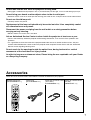
Accessories
Check that all of the accessories shown below have been included with your projector.
Remote control unit
[N2QAGB000024 x 1]
POWER
ON OFF
RGB
1
RGB
2
AUX
MENU
STD
LENS
OSD
1
4
7
2
5
8
3
6
9
0
NEXT
USER
LIGHT
ID ALL
ASPECT
ID SET
Projector
Computer
Numetric
BRIGHT
CONTRAST
ON SCREEN
SYSTEM
SEL
FUNC
1
D.ZOOM
ENTER
PAGE UP
PAGE DOWN
VIDEO
SHUT
S-
VIDEO
FREEZE
SHUTTER
AUTO
SETUP
LASER ON/OFF
Power cord
[K2CF3EH00001 x 1]
Wired cable for remote control
[15m (49'3"),
K1EA03NA0001 x 1]
Battery for remote control
unit (AA)
[R03NPA/2ST x 1]
Do not look into the lens while the projector is being used.
•
Strong light is emitted from the projector’s lens. If you look directly into this light, it can hurt and damage your eyes.
Do not bring your hands or other objects close to the air outlet port.
•
Heated air comes out of the air outlet port. Do not bring your hands or face, or objects which cannot withstand heat.
Do not use the old lamp unit.
• The lamp section may break.
Replacement of the lamp unit should only be carried out after it has completely cooled
off, otherwise burns may result.
Disconnect the power cord plug from the wall outlet as a safety precaution before
carrying out any cleaning.
• Electric shocks can result if this is not done.
Ask an Authorized Service Center to clean inside the projector at least once a year.
• If dust is left to build up inside the projector without being cleaned out, it can result in fire or problems with
operation.
• It is a good idea to clean the inside of the projector before the season for humid weather arrives. Ask your
nearest Authorized Service Center to clean the projector when required. Please discuss with the Authorized
Service Center regarding cleaning costs.
Do not reach for the openings beside the optical lens, during horizontal or vertical
movements of the lens there is a injury hazard.
An effort to keep our environment clean, Please bring the non repairable unit your Dealer
or a Recycling Company.

8
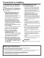
Precautions on handling
Precautions on transport
The projection lens is susceptible to vibrations and
impacts. Be sure to always remove the lens during
transport.
Precautions on installation
Be sure to observe the following precautions when
installing the product.
Avoid installing the product in a place
exposed to vibrations or impacts
.
If the projector is installed in a place where
vibrations are transmitted from a source of
driving power and others or mounted in a car or
a vessel, vibrations or impacts may be
transmitted to the product to damage the internal
parts, causing failure. Install the product in a
place free from vibrations and impacts.
Do not install the projector near high-
voltage power lines or power sources.
The product may be exposed to interference if it
is installed in the vicinity of high-voltage electrical
power lines or power sources.
Do not place the projector on a vinyl
sheet or carpet.
If a vinyl sheet sucked up and blocks the air filter
intake port, the internal temperature of the
projector may increase, which triggers the
protection circuit, turning off the power.
Be sure to ask a specialized
technician when to install the
product to a ceiling.
If the product is to be installed hanging from the
ceiling, purchase an optional hanging attachment
(for high ceiling: Model No. ET-PKD75) (for low
ceiling: Model No. ET-PKD75S) and call a
specialized technician for installation.
Do not place the projector over 2 700 m
(8881.5') above sea level. When using it
over 1 400 m (4605.3') above sea level, set
the “Fan Control”, described on page 78,
to “HIGHLAND”.
Otherwise the life of the product may be shortened.
Precautions on use
To view clear images:
• The audience cannot enjoy high-contrast and
clear images if outside light or the illumination
interferes the screen surface.Draw window
curtains or blinds, turn off the lightings near the
screen or take other proper measures.
• In rare cases, wafture can occur on the screen
affected by the warm air from the exhaust port
depending on the environment.
Do not touch the surface of the
projection lens with bare hand.
If fingerprints or stains are left on the projection
lens surface, they are magnified and projected
on the screen. Keep your hands away from the
lens. Cover the lens with the supplied lens cap
when the projector is not used.
Screen
If the screen has stains, flaws or discoloration,
clear images cannot be viewed. When handling
the screen, be careful not to apply volatile
substances or leave flaws or stains on the screen.
Lamp
A mercury lamp with high internal pressure is used
for the light source of this product. A high-pressure
mercury lamp has the following characteristics:
• It may burst with a loud sound or end its life
cycle by not illuminating because of given
impacts, flaws, or deterioration due to used
hours.
• The life cycle of a mercury lamp varies according
to the individual difference or conditions of use.
In particular, turning the power on and off
frequently and/or repeatedly will greatly affect
the life cycle.
• In rare cases, it may burst shortly after the first
lighting.
• The possibility of burst increases when the lamp
is used beyond the replacement time.
Disposal
To discard the product, call the dealer or a specialized
dealer.
Cleaning and maintenance
Be sure to remove the power cord plug from the receptacle before cleaning.
Use soft and dry cloth to clean the cabinet
If stains are hard to remove, use a cloth dampened with a kitchen detergent solution (neutral) and squeezed
to wipe the cabinet and finish with a dry cloth. If a chemical wipe is used, follow its instructions.
Do not clean the lens surface with fuzzy or dusty cloth.
If dust adheres to the lens, it will be magnified and projected on the screen.
Use a soft and clean cloth to wipe off dust.

9
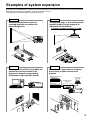
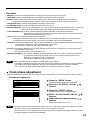
The projector is provided with a number of terminals and optional accessories to enable various system expansions.
Both input and output are provided to all terminals on the main unit.
The following are some examples of system expansion:
Examples of system expansion
System 1
Stacking two projectors with the
stacking brackets can double the
picture brightness.
System 3
PC equipped with a DVI-D input module (an
optional item) can be attached to the
projector for computer image viewing
(Realization of high-resolution picture.)
System 2
The optional high- or low-ceiling mount
bracket flexibly fits the projector in
individual site conditions.
System 4
Connection of a signal selector enables to
feed a variety of video sources to the
projector.
OFF
O
F
F
POWER
O
N
INPUT SE
LECT
1
2
3
45
6
VP
ON/OFF
S
i
g
n
a
l
S
e
l
e
c
t
o
r
T
W
-
S
W
S
Digital broadcasting tuner
or DVD player
Control PC
Signal selector
(Option)
Video deck

10
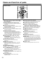
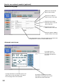
Name and function of parts
< When the operation mode selector is
set to Projector >
Remote control operation indicator lamp
The lamp flashes when any remote control button
is pressed.
POWER ON button (page 39)
Turns on the power if the MAIN POWER has been
put to the “l” position.
POWER OFF button (page 40)
Turns off the power if the MAIN POWER has been
put to the “l” position.
AUTO SET UP button (page 43)
Pressing this button while projecting an image
automatically corrects the picture positioning on the
screen. While the auto setup feature is active, a
message “PROGRESS...” appears on the screen.
Input selector (RGB1, RGB2, AUX, VIDEO,
S-VIDEO) button
Use to toggle through the RGB1, RGB2, AUX
(module input), VIDEO and S-VIDEO input ports.
SHUTTER button (page 48)
Press this button to black out the image
temporarily.
MENU button (page 50)
Displays and clears the Main Menu. It can also
return to the previous screen when the menu is
displayed.
FREEZE button (page 48)
Press this button to freeze the image temporarily.
Arrow buttons (page 50)
Use these buttons to select an item on the menu
screen, change setting and adjust the level.
Also use them to enter the “SECURITY” password.
ENTER button (page 50)
Press this button to enter your menu selection or to
run function.
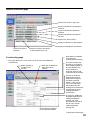
ON SCREEN button
This button turns on and off the on-screen
indication function.
Standard (STD) button (page 50)
Press this button to restore the default factory setting
.
SYSTEM SELECTOR button (page 69)
System switching can be done.
Function 1 (FUNC1) button (page 80)
This button can control the functions set in
“FUNC1” of the “Option” screen from Main Menu.
Digital Zoom (- D.ZOOM +) buttons (page 48)
Any portion of the picture can be zoomed in.
LENS button (page 41)
Switches to the mode of projection lens
adjustment.
CONTRAST button (page 52)
Switches to the mode of image contrast
adjustment.
BRIGHT button (page 52)
Switches to the mode of black level adjustment.
NEXT button
When multiple signal selectors are connected to
the main unit in the system, this button specifies
the second signal selector or beyond. With the ID
set button pressed, every press on the button will
change the value in the ten’s place.
ASPECT button
Switches the image aspect ratio to 4:3, 16:9.
Remote control
POWER
ON OFF
RGB
1
RGB
2
AUX
MENU
STD
LENS
OSD
1
4
7
2
5
8
3
6
9
0
NEXT
USER
LIGHT
ID ALL
ASPECT
ID SET
Projector
Computer
Numetric
BRIGHT
CONTRAST
ON SCREEN
SYSTEM
SEL
FUNC
1
D.ZOOM
ENTER
PAG E UP
PAGE DOWN
VIDEO
SHUT
S-
VIDEO
FREEZE
SHUTTER
AUTO
SETUP
LASER ON/OFF

11
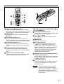
LIGHT button ( Click button)
When this button is pressed, the remote control
button light is turned on.The light goes off about 30
seconds after you stop remote control operation.
USER button
Displays the sub-memory screen of the signal
registration.
ID ALL button (pages 16,71)
When two or more main units are used in the
system, this button switches to the mode to control
them simultaneously with a single remote control.
ID SET button (pages 16,71)
When two or more main units are used in the
system, this button specifies the ID of the remote
control.
Remote control wired terminal (page 17)
To use the wired output terminal, connect the
remote control and the main unit with the supplied
cable.
Remote control transmitter window
Operate the remote control aiming at the remote
control receiver window on the main unit.
P
A
G
E
D
O
W
N
L
A
S
E
R
O
N
/
O
F
F
PAG E
PAG E
P
O
W
E
R
O
NO
F
F
R
G
B
1
R
G
B
2
A
U
X
MENU
ENTE
R
P
A
G
E
U
P
VIDEO
SHUT
S
-
V
I
D
E
O
F
R
E
E
Z
E
S
HUTTER
A
U
T
O
S
E
T
U
P
S
T
D
L
E
N
S
O
S
D
1
4
7
2
5
8
3
6
9
0
N
E
X
T
USER
L
IG
H
T
ID
A
L
L
ID
S
E
T
P
ro
je
c
t
o
r
Computer
N
u
m
e
tric
B
RIGHT
C
O
N
T
R
A
S
T
O
N
S
C
R
E
E
N
S
Y
S
T
E
M
SEL
F
U
N
C
1
D.ZOOM
ASPECT
POWER
ON OFF
RGB
1
RGB
2
AUX
MENU
STD
LENS
OSD
1
4
7
2
5
8
3
6
9
0
NEXT
USER
LIGHT
ID ALL
ASPECT
ID SET
Projector
Computer
Numetric
BRIGHT
CONTRAST
ON SCREEN
SYSTEM
SEL
FUNC
1
D.ZOOM
ENTER
PAG E UP
PAG E DOWN
VIDEO
SHUT
S-
VIDEO
FREEZE
SHUTTER
AUTO
SETUP
LASER ON/OFF
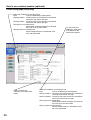
<When the operation mode selector is
set to Computer>
PAGE UP/PAGE DOWN buttons
These buttons correspond to the PAGE UP/PAGE
DOWN buttons on PC's keyboard.
( ) buttons
These buttons correspond to the left and right
mouse buttons.
ENTER button
Moves the mouse cursor.
Numeric (0-9) buttons
In a system that uses two or more units of this
projector or in a system that connects to an
optional signal selector, these buttons specify a
particular projector unit or the input of the signal
selector. They are also used to input the ID
number when selecting the ID and to enter the
password when the password for service
personnel needs to be entered.
Operation mode selector (Computer/Numeric,
Projector) switch (page 17)
Put this selector to the right position to control the
projector and to the left position to control the PC
or use numeric buttons.
Click button (page 17)
This button corresponds to the left mouse button
when the operation mode is switched to the
Computer position.
• To use the remote control as a mouse,
please purchase an optional wireless
mouse receiver (model No.: ET-RMRC2).
• The AUX button to switch the input is
disabled when an optional input module is
not connected.
Note

12
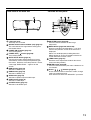
Side-mounted
connection terminals
(page 14)
AC IN terminal (page 39)
Connect the supplied line power cord into this
receptacle.
Do not connect any other cable to this socket.
MAIN POWER switch (page 39)
Use this switch to turn on “I” and off “
o
” the
commercial line power applied to the projector.
Burglar lock
Attach a commercial burglar prevention cable (e.g.,
from Kensington) to this lock port. It is compatible
with the Micro Save Security System from
Kensington. This security lock is compatible with the
Microsaver Security System from Kensington.
Contact details for this company are given below.
Kensington Technology Group ACCO Brands Inc.
2885 Campus Drive San Mateo, CA94403
Tel (650)572-2700
Fax (650)572-9675
http://www.kensington.com/
http://www.gravis.com/
Remote control receiver window (front) (page 15)
This window receives the signal beam emitted from
the remote control.
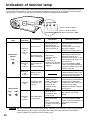
Power indicator lamp (page 39)
The lamp lights in red when the MAIN POWER
switch is turned to “I” (on). It turns to green when
the POWER ON button of the remote control or the
main unit is pressed.
LAMP1 monitor (page 98)
This lamp lights up when the time to replace lamp
unit 1 is reached. It also blinks if something
unusual occurs in the lamp circuit.
Projection lens (optional)
Lens for projecting images on the screen.
Projection lens cover lock button
This button toggles between lock and unlock of the
detachable cover for the projection lens (optional).
Temperature monitor (TEMP) (page 98)
Lighting or blinking of this lamp indicates an
abnormal condition of the internal temperature.
LAMP2 monitor (page 98)
This lamp lights up when the time to replace lamp
unit 2 is reached. It also blinks if something
unusual occurs in the lamp circuit.
Air filter (page 99)
Level-adjusting feet (page 18)
Use these feet to adjust the tilt of the projector.
(Leveling feet are provided at the front and rear,
right and left.)
Name and function of parts
Front and side of the projector

13
Lamp unit cover
The lamp unit is housed.
Remote control receiver window (rear) (page 15)
This also receives the signal beam coming from
the remote control.
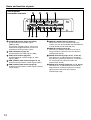
POWER ON (I) button (page 39)
Turns on the power.
POWER OFF ( ) button (page 40)
Turns off the power.
AUTO SETUP button (page 43)
Pressing this button while projecting an image
automatically corrects the picture positioning on
the screen. While the auto setup feature is active,
a message “EXECUTING...” appears on the
screen.
RGB1 button (page 39)
Switches to RGB1 input.
RGB2 button (page 39)
Switches to RGB2 input.
AUX button (page 39)
Switches to optional input module input.
VIDEO button (page 39)
Switches to video input.
S-VIDEO button (page 39)
Switches to S-VIDEO input.
SHUTTER button (page 48)
Press this button to black out the image
temporarily.
MENU button (pages 50 and 88–89)
Displays and clears the Main Menu. It can also
return to the previous screen when the menu is
displayed.
Menus can be displayed by holding down the
MENU button for at least 3 seconds while the on-
screen indication function is OFF.
LENS button (page 41)
Switches to the adjustment mode for lens focus,
zoom and shift (position).
ENTER button (page 50)
Press this button to enter your menu selection or to
run function.
Arrow ( ) buttons (page 50)
Use to select an item on the menu screen, change
setting and adjust the level.
Also use them to enter the “SECURITY” password.
Rear view of the main unit Controls on rear panel
AUTO
SETUP
RGB 1
VIDEO
MENU
ENTER
LENS
S-VIDEO
SHUTTER
RGB 2
AUX

14
S-VIDEO IN terminal (pages 24 and 25)
An input terminal for S-video signals
(MIN4-pin DIN).
This terminal complies with S1 signals and
automatically toggles between 16:9 and 4:3
according to the size of input signals.
VIDEO IN terminal (page 25)
An input terminal for video signals. (BNC)
VIDEO OUT terminal (page 25)
An output terminal (active through) for video
signals. (BNC)
RGB (YPBPR)1 input terminal (pages 26, 27)
A terminal to input RGB or YPBPR signals (BNC).
RGB (YPBPR)2 input terminal (page 26)
A terminal to input RGB or YPBPR signals (D-SUB
15-pin female).
REMOTE1 lN/OUT terminal (page 17)
When two or more main units are used in the
system, they can be connected and controlled with
a wired remote control cable (M3 jack).
REMOTE2 terminal (page 84)
The user can remotely control the main unit by
using an external control circuit to this terminal
(D-SUB 9-pin female).
SERIAL IN terminal (pages 25–27, 74, 82, 83)
This terminal is an RS-232C/RS-422 compliant
input terminal (switching necessary) to connect a
PC and to externally control the main unit
(D-SUB 9-pin female).
SERIAL OUT terminal (pages 26, 27, 74, 82, 83)
This terminal is an RS-232C/RS-422 compliant
output terminal (switching necessary) to supply
signals given to the serial input terminal
(D-SUB 9-pin male).
SERIAL
S-VIDEO
RGB 2 IN
VIDEO
REMOTE 1
RGB 1 IN
IN
IN
IN
OUT
OUT
OUT
SYNC/HD VDB/PBG/Y
REMOTE 2
R/PR
RS-232C (G) / RS-422 (R)RS-232C (G) / RS-422 (R)
IN
Side-mounted
connection terminals
Name and function of parts

15
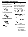
Loading dry cells
When loading supplied AA dry cells into the battery
compartment of the remote control, make sure that
their polarities are correct.
1. Open battery compartment lid.
Open the lid in the order of steps and .
2. Insert the dry cells.
Into battery compartment, with their polarities
orientated as indicated ( , )in the
compartment.
3. Close the battery compartment lid.
Replace the battery compartment lid over the
compartment and slide until it clicks.
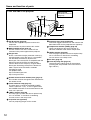
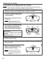
Effective range of remote
control operation
The remote control should normally be aimed at either
the front or rear remote control receiver window on the
projector (figure 1). Otherwise, it may also be aimed at
the screen, which will reflect commands back to the
projector's front receiver window as illustrated in figure 2.
The effective control range is approx. 7 meters from
the beam receiver on the front or rear.
• Do not drop the remote control unit.
• Do not expose remote control unit to
any liquid.
• Do not use NiCd batteries.
Attention
• When the remote control is aimed at
the screen, the effective control range
may be reduced due to the optical loss
by screen reflection.
• The remote control may not function
properly if an object is in the light path.
• The remote control receiver may not
function properly in intense ambient
light such as fluorescent lamps.
Carefully site the projector so its
remote control receiver windows will
not be directly exposed to intense light.
Supplied AA dry cells
(insert the side first).
(Front) (Rear)
[Top view]
Remote
control
30˚
30˚
30˚
30˚
[Side view]
15˚
15˚
15˚
15˚
Remote
control
Remote
control
Remote
control
Screen
Projector
Remote control
receiver window
(front)
Remote control
receiver window
(rear)
Remote control
Using the remote control unit
Note
Figure 2
Figure 1

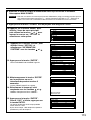
16
Every projector has its ID number and the ID number of the controlling projector must be set to the remote control
in advance so that the user can operate the remote control. The ID number of the projector is set to “ALL” on
shipping, and use the ID ALL button of the remote control when using only a single projector.
Procedure of ID setting
Change the position of the operation mode selector switch to “Computer”.
Press the ID SET button, and within five seconds, use the NEXT button to set the
number of the tens digit in the ID number, which is already set in the projector, and
then use one of the numeric (0-9) buttons to set the number of the units digit.
Change the position of the operation mode selector switch to “Projector”.
However, if the ID ALL button is pressed, the projector can be controlled regardless of the ID number of the
projector (simultaneous control mode).
Using the remote control unit
Setting projector ID number to remote control
• Do not press the ID SET button accidentally or carelessly because the ID number on the remote
control can be set even when no projector is around.
If the ID SET button is pressed, the ID number goes back to the one set before pressing the ID
SET button unless the NEXT button and a numeric button are pressed within five seconds after
the ID SET button is pressed.
• Your specified ID number is stored in the remote control unit unless another one is specified later.
However, the stored ID will be erased if the batteries of the remote control are left exhausted.
When the dry cells are replaced, set the same ID number again.
Attention

17
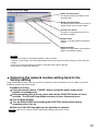
Using the remote control as a PC mouse
Operation mode selector switch
Put the knob to the Computer position.
• ENTER button
Pressing the front, rear, left and right edges of the
button moves the mouse cursor up, down, left and
right.
• Right click ( ) button
This button can be used as the right mouse button.
• Left click ( ) button
This button can be used as the left mouse button.
• PAGE UP button
This button can be used as the Page Up button on the
PC keyboard.
• PAGE DOWN button
This button can be used as the Page Down button on
the PC keyboard.
• Click button
This button can be used as the left mouse button.
POWER
ON OFF
RGB
1
RGB
2
AUX
MENU
STD
LENS
OSD
1
4
7
2
5
8
3
6
9
0
NEXT
USER
LIGHT
ID ALL
ASPECT
ID SET
Projector
Computer
Numetric
BRIGHT
CONTRAST
ON SCREEN
SYSTEM
SEL
FUNC
1
D.ZOOM
ENTER
PAGE UP
PAGE DOWN
VIDEO
SHUT
S-
VIDEO
FREEZE
SHUTTER
AUTO
SETUP
LASER ON/OFF
PAGE DOWN button
Operation mode
selector switch
ENTER button
Right click ( ) button
PAGE UP button
Left click
( ) button
P
A
G
E
DOWN
LASE
R O
N/OFF
P
A
G
E
P
A
G
E
P
O
W
E
R
ON
OFF
R
G
B
1
R
G
B
2
AUX
M
E
N
U
ENTER
P
A
G
E
UP
V
I
D
E
O
S
H
U
T
S-
V
I
D
E
O
F
R
E
E
Z
E
S
H
U
T
T
E
R
A
U
T
O
SE
TU
P
STD
LENS
OSD
1
4
7
2
5
8
3
6
9
0
NEXT
U
S
E
R
LIGHT
ID ALL
I
D
S
E
T
P
r
o
j
e
c
t
o
r
C
o
m
p
u
t
e
r
N
u
m
e
tr
ic
B
R
IG
H
T
C
O
N
T
R
A
S
T
O
N
S
C
R
E
E
N
S
Y
S
T
E
M
S
E
L
F
U
N
C
1
D
.Z
O
O
M
A
S
P
E
C
T
Click button
• To use the remote control as a mouse,
please purchase an optional wireless
mouse receiver (model No.: ET-RMRC2).
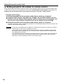
When multiple main units are connected in the system,
connect the units with the supplied remote control
cable to simultaneously control the multiple main units
with a single remote control unit through the
SERIAL
S-VIDEO
RGB 2 IN / RGB 1 OUT
VIDEO
REMOTE 1
RGB 1 IN
IN
IN
IN
OUT
OUT
OUT
SYNC/HD VDB/PBG/Y
REMOTE 2
R/PR
RS-232C (G) / RS-422 (R)RS-232C (G) / RS-422 (R)
IN
POWER
ON OFF
RGB
1
RGB
2
AUX
MENU
STD
LENS
OSD
1
4
7
2
5
8
3
6
9
0
NEXT
USER
LIGHT
ID ALL
ASPECT
ID SET
Projector
Computer
Numetric
BRIGHT
CONTRAST
ON SCREEN
SYSTEM
SEL
FUNC
1
D.ZOOM
ENTER
PAGE UP
PAGE DOWN
VIDEO
SHUT
S-
VIDEO
FREEZE
SHUTTER
AUTO
SETUP
LASER ON/OFF
Side-mounted terminals
Connect to the
secondary projector
Remote control
Remote control cable
(supplied)
Using a wired remote control
REMOTE1 IN/OUT terminal. It is effective to use the
wired remote control in the environment in which an
obstacle stands in the light path or where devices are
susceptible to outside light.
Note

18
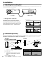
Projection scheme
This projector can use any of the four projection
schemes shown at right. Select the scheme that best
suits your particular installation location. Select the
most suitable scheme to the situation of your location.
Use the OPTION menu on the menu screen to choose
the desired projection scheme. (Refer to page 72)
Rear projection
Front projection
Table standing
Ceiling mount
Table standing
Ceiling mount
(Default position)
< Front > < Side >
Leveling feet
Installation
Adjusting the leveling feet
The four leveling feet mounted at the bottom of the projector are level-adjustable (0 mm–33 mm) which can be used
when the floor surface is not horizontal.
Installation geometry
When planning the projector and screen geometry, refer to the figures below and the information on the next page
for reference. After the projector is roughly positioned, picture size and vertical picture positioning can be finely
adjusted with the powered zoom lens and lens shifting mechanism.
H
SH
L
L
H
Side view
When optional ceiling
mount bracket (ET-PKD75)
Screen
(unit: mm/inch)
438-558
(17.2"-21.9")
237
(9.3")
L
SW
314
86
140
175
468
117
L1
Top view
Screen
(unit: mm/inch)
(18.4")
(5.5")
(12.3")
(3.4")
(6.9")
(4.6")
L : Projection distance
SH : Height of the image
SW : Image width
H : Vertical distance between the lens center
level and the bottom edge of the projected
image
For PT-D7700U: H = 0 to SH
For PT-DW7000U: H = -0.18 x SH to 1.18 x SH
Lens Dimension of L1 (Approx.)
ET-D75LE1 102 (4")
ET-D75LE2 86.5 (3.4")
ET-D75LE3 90 (3.5")
ET-D75LE4 113.9 (4.5")
ET-D75LE5 190 (7.5")
ET-D75LE8 242 (9.5")

19
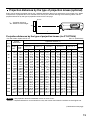
L : Projection distance
SH : Effective screen height
L
SH
Screen
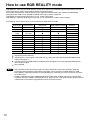
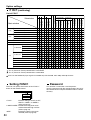
Projection distances by the type of projection lenses (for PT-D7700U)
• For the screen aspect ratio of 4:3 Units: m (feet/inches)
• The projection distances listed here involve an error of ±5%.
• Keystone distortions are corrected in the way the screen size becomes smaller than the original one.
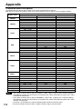
Projection distances by the type of projection lenses (optional)
Every type of optional projection lenses has a different projection distance to achieve the same screen size. Select
and purchase a projection lens most suitable to the size of your location referring to the following tables and the
projection distances by the type of projection lenses on the next page.
Screen
size
(inch)
Screen
dimensions
70
80
90
100
120
150
200
250
300
350
400
500
600
1.066
(3'6")
1.219
(4'0")
1.371
(4'6")
1.524
(5'0")
1.828
(6'0")
2.286
(7'6")
3.048
(10'0")
3.810
(12'6")
4.572
(15'0")
5.334
(17'6")
6.096
(20'0")
7.620
(25'0")
9.144
(30'0")
1.422
(4'8")
1.625
(5'4")
1.828
(6'0")
2.032
(6'8")
2.438
(8'0")
3.048
(10'0")
4.064
(13'4")
5.080
(16'8")
6.096
(20'0")
7.112
(23'4")
8.129
(26'8")
10.160
(33'4")
12.192
(40'0")
Effective
width
(SW)
1.02
1.18
1.34
1.50
1.81
2.29
3.08
3.87
4.66
(3'4'')
(3'10'')
(4'4'')
(4'11'')
(5'11'')
(7'6'')
(10'1'')
(12'8'')
(15'3'')
-----
-----
-----
-----
11.37
13.01
14.65
16.29
19.57
24.49
32.69
40.88
49.08
57.28
65.47
81.87
98.26
(37'3'')
(42'8'')
(48')
(53'5'')
(64'2'')
(80'4'')
(107'3'')
(134'1'')
(161')
(187'11'')
(214'9'')
(268'7'')
(322'4'')
7.10
8.13
9.16
10.19
12.26
15.35
20.50
25.66
30.81
35.97
41.12
51.43
61.74
(23'3'')
(26'8'')
(30')
(33'5'')
(40'2'')
(50'4'')
(67'3'')
(84'2'')
(101')
(118')
(134'10'')
(168'8'')
(202'6'')
7.09
8.13
9.16
10.19
12.25
15.34
20.50
25.65
30.81
35.96
41.12
51.42
61.73
(23'3'')
(26'8'')
(30')
(33'5'')
(40'2'')
(50'3'')
(67'3'')
(84'1'')
(101')
(117'11'')
(134'10'')
(168'8'')
(202'6'')
4.23
4.84
5.46
6.08
7.31
9.16
12.25
15.34
18.42
21.51
24.60
30.77
36.94
(13'10'')
(15'10'')
(17'10'')
(19'11'')
(23'11'')
(30')
(40'2'')
(50'3'')
(60'5'')
(70'6'')
(80'8'')
(100'11'')
(121'2'')
4.21
4.83
5.45
6.07
7.30
9.15
12.24
15.33
18.41
21.50
24.58
30.76
36.93
(13'9'')
(15'10'')
(17'10'')
(19'10'')
(23'11'')
(30')
(40'1'')
(50'3'')
(60'4'')
(70'6'')
(80'7'')
(100'11'')
(121'1'')
2.80
3.21
3.62
4.04
4.86
6.09
8.15
10.21
12.27
14.32
16.38
20.50
24.61
(9'2'')
(10'6'')
(11'10'')
(13'3'')
(15'11'')
(19'11'')
(26'8'')
(33'5'')
(40'3'')
(46'11'')
(53'8'')
(67'3'')
(80'8'')
2.77
3.18
3.59
4.00
4.82
6.05
8.10
10.15
12.19
14.24
16.29
20.39
24.49
(9'1'')
(10'5'')
(11'9'')
(13'1'')
(15'9'')
(19'10'')
(26'6'')
(33'3'')
(39'11'')
(46'8'')
(53'5'')
(66'10'')
(80'4'')
2.07
2.38
2.68
2.99
3.60
4.53
6.06
7.59
9.13
10.66
12.19
15.26
18.33
(6'9'')
(7'9'')
(8'9'')
(9'9'')
(11'9'')
(14'10'')
(19'10'')
(24'10'')
(29'11'')
(34'11'')
(39'11'')
(50')
(60'1'')
Minimum
Maximum
ET-D75LE1
(1.5-2.0 :1)
Minimum
Maximum
ET-D75LE2
(2.0-3.0 :1)
Minimum
Maximum
ET-D75LE3
(3.0-5.0 :1)
Minimum
Maximum
ET-D75LE4
(5.0-8.0 :1)
ET-D75LE5
(0.8 : 1)
Projection distance (L)
Zoom lens
Fixed-
focus lens
21.14
24.22
27.29
30.36
36.50
45.72
61.08
76.44
91.79
107.15
122.51
153.23
183.95
(69'4'')
(79'5'')
(89'6'')
(99'7'')
(119'9'')
(150')
(200'4'')
(250'9'')
(301'1'')
(351'6'')
(401'11'')
(502'8'')
(603'6'')
11.09
12.73
14.37
16.01
19.29
24.21
32.40
40.60
48.80
57.00
65.19
81.59
97.98
(36'4'')
(41'9'')
(47'1'')
(52'6'')
(63'3'')
(79'5'')
(106'3'')
(133'2'')
(160'1'')
(187')
(213'10'')
(267'8'')
(321'5'')
Minimum
Maximum
ET-D75LE8
(8.0-15.0 :1)
Effective
height
(SH)
Note
(Continued on next page)

20
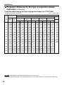
• The projection distances listed here involve an error of ±5%.
• Keystone distortions are corrected in the way the screen size becomes smaller than the original one.
Installation
Projection distances by the type of projection lenses
(optional) (continuing)
Projection distances by the type of projection lenses (for PT-D7700U)
• For the screen aspect ratio of 16:9 Units: m (feet/inches)
Note
Screen
size
(inch)
Screen
dimensions
70
80
90
100
120
150
200
250
300
350
400
500
600
0.871
(2'10")
0.996
(3'3")
1.120
(3'8")
1.245
(4'1")
1.494
(4'11")
1.868
(6'2")
2.491
(8'2")
3.113
(10'3")
3.736
(12'3")
4.358
(14'4")
4.981
(16'4")
6.226
(20'5")
7.472
(24'7")
1.549
(5'1")
1.771
(5'10")
1.992
(6'7")
2.214
(7'3")
2.657
(8'9")
3.321
(10'11")
4.428
(14'6")
5.535
(18'2")
6.641
(21'70")
7.748
(25'5")
8.855
(29'0")
11.069
(36'4")
13.282
(43'8")
Effective
width
(SW)
1.12
1.29
1.47
1.64
1.98
2.50
3.36
4.22
5.08
(3'8'')
(4'2'')
(4'9'')
(5'4'')
(6'5'')
(8'2'')
(11')
(13'10'')
(16'8'')
-----
-----
-----
-----
12.40
14.19
15.97
17.76
21.33
26.69
35.61
44.54
53.47
62.40
71.33
89.19
107.04
(40'8'')
(46'6'')
(52'4'')
(58'3'')
(69'11'')
(87'6'')
(116'9'')
(146'1'')
(175'5'')
(204'8'')
(234')
(292'7'')
(351'2'')
7.75
8.87
9.99
11.11
13.36
16.73
22.34
27.96
33.57
39.19
44.80
56.03
67.26
(25'5'')
(29'1'')
(32'9'')
(36'5'')
(43'9'')
(54'10'')
(73'3'')
(91'8'')
(110'1'')
(128'6'')
(146'11'')
(183'9'')
(220'8'')
7.74
8.86
9.99
11.11
13.35
16.72
22.34
27.95
33.57
39.18
44.80
56.03
67.26
(25'4'')
(29')
(32'9'')
(36'5'')
(43'9'')
(54'10'')
(73'3'')
(91'8'')
(110'1'')
(128'6'')
(146'11'')
(183'9'')
(220'8'')
4.61
5.28
5.96
6.63
7.97
9.99
13.35
16.71
20.08
23.44
26.80
33.53
40.25
(15'1'')
(17'3'')
(19'6'')
(21'9'')
(26'1'')
(32'9'')
(43'9'')
(54'9'')
(65'10'')
(76'10'')
(87'11'')
(110')
(132')
4.60
5.27
5.95
6.62
7.96
9.98
13.34
16.70
20.07
23.43
26.79
33.51
40.24
(15'1'')
(17'3'')
(19'6'')
(21'8'')
(26'1'')
(32'8'')
(43'9'')
(54'9'')
(65'10'')
(76'10'')
(87'10'')
(109'11'')
(132')
3.06
3.51
3.96
4.40
5.30
6.65
8.89
11.13
13.37
15.61
17.85
22.33
26.82
(10')
(11'6'')
(12'11'')
(14'5'')
(17'4'')
(21'9'')
(29'2'')
(36'6'')
(43'10'')
(51'2'')
(58'6'')
(73'3'')
(87'11'')
3.03
3.47
3.92
4.36
5.26
6.60
8.83
11.06
13.29
15.53
17.76
22.22
26.69
(9'11'')
(11'4'')
(12'10'')
(14'3'')
(17'3'')
(21'7'')
(28'11'')
(36'3'')
(43'7'')
(50'11'')
(58'3'')
(72'10'')
(87'6'')
2.26
2.60
2.93
3.27
3.93
4.94
6.61
8.28
9.95
11.62
13.29
16.63
19.97
(7'4'')
(8'6'')
(9'7'')
(10'8'')
(12'10'')
(16'2'')
(21'8'')
(27'1'')
(32'7'')
(38'1'')
(43'7'')
(54'6'')
(65'6'')
Minimum
Maximum
ET-D75LE1
(1.5-2.0 :1)
Minimum
Maximum
ET-D75LE2
(2.0-3.0 :1)
Minimum
Maximum
ET-D75LE3
(3.0-5.0 :1)
Minimum
Maximum
ET-D75LE4
(5.0-8.0 :1)
ET-D75LE5
(0.8 : 1)
Projection distance (L)
Zoom lens
Fixed-
focus lens
23.06
26.41
29.76
33.10
39.79
49.83
66.56
83.29
100.02
116.75
133.49
166.95
200.41
(75'7'')
(86'7'')
(97'7'')
(108'7'')
(130'6'')
(163'5'')
(218'4'')
(273'3'')
(328'1'')
(383')
(437'11'')
(547'8'')
(657'6'')
12.12
13.90
15.69
17.47
21.05
26.40
35.33
44.26
53.19
62.12
71.05
88.91
106.77
(39'9'')
(45'7'')
(51'5'')
(57'3'')
(69')
(86'7'')
(115'10'')
(145'2'')
(174'6'')
(203'9'')
(233'1'')
(291'8'')
(350'3'')
Minimum
Maximum
ET-D75LE8
(8.0-15.0 :1)
Effective
height
(SH)
La page charge ...
La page charge ...
La page charge ...
La page charge ...
La page charge ...
La page charge ...
La page charge ...
La page charge ...
La page charge ...
La page charge ...
La page charge ...
La page charge ...
La page charge ...
La page charge ...
La page charge ...
La page charge ...
La page charge ...
La page charge ...
La page charge ...
La page charge ...
La page charge ...
La page charge ...
La page charge ...
La page charge ...
La page charge ...
La page charge ...
La page charge ...
La page charge ...
La page charge ...
La page charge ...
La page charge ...
La page charge ...
La page charge ...
La page charge ...
La page charge ...
La page charge ...
La page charge ...
La page charge ...
La page charge ...
La page charge ...
La page charge ...
La page charge ...
La page charge ...
La page charge ...
La page charge ...
La page charge ...
La page charge ...
La page charge ...
La page charge ...
La page charge ...
La page charge ...
La page charge ...
La page charge ...
La page charge ...
La page charge ...
La page charge ...
La page charge ...
La page charge ...
La page charge ...
La page charge ...
La page charge ...
La page charge ...
La page charge ...
La page charge ...
La page charge ...
La page charge ...
La page charge ...
La page charge ...
La page charge ...
La page charge ...
La page charge ...
La page charge ...
La page charge ...
La page charge ...
La page charge ...
La page charge ...
La page charge ...
La page charge ...
La page charge ...
La page charge ...
La page charge ...
La page charge ...
La page charge ...
La page charge ...
La page charge ...
La page charge ...
La page charge ...
La page charge ...
La page charge ...
La page charge ...
La page charge ...
La page charge ...
La page charge ...
La page charge ...
La page charge ...
La page charge ...
-
 1
1
-
 2
2
-
 3
3
-
 4
4
-
 5
5
-
 6
6
-
 7
7
-
 8
8
-
 9
9
-
 10
10
-
 11
11
-
 12
12
-
 13
13
-
 14
14
-
 15
15
-
 16
16
-
 17
17
-
 18
18
-
 19
19
-
 20
20
-
 21
21
-
 22
22
-
 23
23
-
 24
24
-
 25
25
-
 26
26
-
 27
27
-
 28
28
-
 29
29
-
 30
30
-
 31
31
-
 32
32
-
 33
33
-
 34
34
-
 35
35
-
 36
36
-
 37
37
-
 38
38
-
 39
39
-
 40
40
-
 41
41
-
 42
42
-
 43
43
-
 44
44
-
 45
45
-
 46
46
-
 47
47
-
 48
48
-
 49
49
-
 50
50
-
 51
51
-
 52
52
-
 53
53
-
 54
54
-
 55
55
-
 56
56
-
 57
57
-
 58
58
-
 59
59
-
 60
60
-
 61
61
-
 62
62
-
 63
63
-
 64
64
-
 65
65
-
 66
66
-
 67
67
-
 68
68
-
 69
69
-
 70
70
-
 71
71
-
 72
72
-
 73
73
-
 74
74
-
 75
75
-
 76
76
-
 77
77
-
 78
78
-
 79
79
-
 80
80
-
 81
81
-
 82
82
-
 83
83
-
 84
84
-
 85
85
-
 86
86
-
 87
87
-
 88
88
-
 89
89
-
 90
90
-
 91
91
-
 92
92
-
 93
93
-
 94
94
-
 95
95
-
 96
96
-
 97
97
-
 98
98
-
 99
99
-
 100
100
-
 101
101
-
 102
102
-
 103
103
-
 104
104
-
 105
105
-
 106
106
-
 107
107
-
 108
108
-
 109
109
-
 110
110
-
 111
111
-
 112
112
-
 113
113
-
 114
114
-
 115
115
-
 116
116


Panasonic DW7000U-K - WXGA DLP Projector Manuel utilisateur
- Catégorie
- Projecteurs de données
- Taper
- Manuel utilisateur
dans d''autres langues
Documents connexes
-
Panasonic PTL520U Manuel utilisateur
-
Panasonic Projection Television LB20NTU Manuel utilisateur
-
Panasonic PTL785U Manuel utilisateur
-
-
-
-
-
Panasonic PTD7700E Mode d'emploi
-
Panasonic BTH1700BP - IND. MONITOR Operating Instructions Manual
-
Autres documents
-
Proxima ASA DP6850 Manuel utilisateur
-
Sanyo PLC-EF60A Quick Reference Manual
-
Hitachi CP-X960E Manuel utilisateur
-
Christie L2K1000 Manuel utilisateur
-
Christie LX505 Manuel utilisateur
-
Eiki EK-700LU Manuel utilisateur
-
Christie DHD800 Manuel utilisateur
-
Philips PT-LB51SU Manuel utilisateur
-
Sony VPL-VW295ES Operating Instructions Manual
-