
Questions? If you have questions regarding installation, operation or maintenance of this kit, call toll-free 800/562-6587 for assistance,
Monday through Friday, 9 AM to 5 PM EST. Online: http://www.easyheat.com
Questions? Si vous avez des questions concernant l’installation, l’utilisation ou l’entretien de cette trousse, veuillez appeler sans frais au 800/562-6587
pour obtenir de l’aide du lundi au vendredi, de 9 h à 17 h HNE. En ligne : http://www.easyheat.com
¿Preguntas? Si tiene preguntas relativas a la instalación, el funcionamiento o el mantenimiento de este kit, llame sin cargo al teléfono 800/562-6587
para asistencia técnica, de lunes a viernes, de 9:00 AM a 5:00 PM hora del este. En línea: http://www.easyheat.com.
READ, SAVE AND PASS ON these instructions to anyone who will be
using this cable, including future users/homeowners.
©2005 Easy Heat
LISEZ, GARDEZ ET PASSEZ ces directives
à toute personne qui utilisera ce câble, y compris les futurs utilisateurs ou
propriétaires de maison.
©2005 Easy Heat
LEA, GUARDE Y TRANSMITA estas instrucciones a cualquier persona que
vaya a utilizar este cable, incluyendo futuros usuarios o propietarios.
©2005 Easy Heat
The Underwriters Laboratory (UL) listing to Canadian safety standards and the
Canadian Standards Association (CSA) certification are valid only when the kit is
installed, used, operated and maintained according to the following instructions.
L’homologation de l’Underwriters Laboratory (UL) pour les normes de sécurité
canadienne et l’agrément de l’ACNOR ne sont valides que si la trousse est installée,
utilisée, exploitée et entretenue selon les directives ci-dessous.
La certificación de Underwriters Laboratory (UL) registrada ante las normas
canadienses de seguridad y la Canadian Standards Association (CSA) es valida
únicamente si el kit es instalado, utilizado, puesto en funcionamiento y mantenido
de acuerdo con estas instrucciones.
11629 001 Rev. 2 ©2005 Easy Heat
Roof & Gutter De-Icing Kit
Model ADKS Owner’s Manual
Trousse de dégivrage de toits et de gouttières
Modèle ADKS guide de l’utilisateur
Kit descongelante para techos y canalones
Modelo ADKS guía del usuario

ESP
68 Modelo ADKS guía del usuario
Cuadro B-3 Kits Descongelantes RC
Número de Catálogo L argo
Pies Metros
ADKS-100 20 6
ADKS-150 30 9
ADKS-300 60 18
ADKS-400 80 24
ADKS-500 100 31
ADKS-600 120 37
ADKS-800 160 49
ADKS-1000 200 61
ADKS-1200 240 73
B. PROBLEMAS ÚNICAMENTE EN LOS CANALONES
Si la acumulación de hielo ocurre únicamente en los canalones, tome las medidas correspondientes (véase la Figura B-2) y calcule el largo del cable
necesario para cada sección de la lista en el cuadro B-4. Sume las medidas de cada zona para determinar el largo total del cable necesario.
Cuadro B-4 Cable Necesario únicamente en canalones con
problemas de hielo
Zona Cómo calcular
Canalón Largo del canalón X 2
Bajadas de agua Número de bajadas de agua X el largo de la bajadas de agua (D) X 2
PASO 2. Utilice el largo estimado del cable que se calculó para selec-
cionar el cable apropiado en el cuadro B-3. En general, escoga
el cable más largo si el largo del cable necesario se encuentra
entre dos tamaños ofrecidos. Si la diferencia es pequeña, (me-
nos de 5 pies [1.50 m] aproximadamente), se puede utilizar un
cable más corto. No se puede modificar el cable cortándolo,
añadiéndolo ni alterándolo de ninguna forma.
Si la acumulación de hielo ocurre en zonas muy separadas,
es posible utilizar cables diferentes para cada zona en vez de
uno solo. También se deben usar cables separados si las zonas
del techo son grandes.
C. TECHOS CON APLICACIONES ESPECIALES
PASO 1. Para cada zona de la lista del cuadro B-5, tome las medidas correspondientes (véase las Figura B-1 en la página 67 y B-3 en la página 69) y
calcule el largo del cable necesario. Sume la medida de cada una de las “zonas” para determinar el total del largo del cable necesario.
Zona Se debe medir Cómo calcular
A lo largo del techo Alero (A) Largo del techo (B) X multiplicador del alero (véase Cuadro B-2)
Largo del techos (B)*
Buhardilla Distancia alrededor de la buhardilla (C) Número de buhardillas X distancia alrededor de las buhardillas (C)
Línea de pendiente Número de líneas de pendiente (D) Número de líneas de pendiente (D) X 6 pies o 1.8 metros
Bajadas de agua Número de bajadas de agua Número de bajadas de agua X largo de la bajadas de agua (E) X 2
Largo de las bajadas de agua desde el techo al piso (E)
Zonas especiales Distancia desde el borde del alero hasta Distancia desde el borde del alero hasta el extremo de la zona
del techo (tragaluces) el extremo de la zona especial del techo (F) especial del techo (F) X Ancho de la acumulación de hielo que se
Ancho de la acumulación de hielo que se forma forma a lo largo de la zona específica del techo (G) X
a lo largo de la zona específica del techo (G) Multiplicador de la zona especial del techo (véase el cuadro B-6)
*Nota: No se incluye el ancho de las zonas especiales (G) en esta medida.
Cuadro B-5
Model ADKS Owner’s Manual
ADKS Owner’s Manual 1
ENG
Roof & Gutter
De-Icing Kit

ENGLISH, 1 - 23
FRENCH, 25 - 46
SPANISH, 49 - 69
2 ADKS Owner’s Manual
ENG
ESP
Una estimación adecuada del largo del cable necesario es importante
debido a que no se puede modificar el cable cortándolo, añadiéndolo
ni alterándolo de ninguna manera. Esto, puede causar incendio, choque
eléctrico o acumulación de hielo.
Si debe instalar el cable en las zonas en donde se acumula el hielo. Puedo
ser ser la totalidad del alero del techo, o únicamente zonas específicas
como por ejemplo, debajo de los tragaluces, en las líneas de pendiente
del techo o alrededor de las buhardillas. Tambíen se debe iinstalar el cable
en los canalones debajo de alero, en las bajadas de agua y en las líneas de
pendiente del techo.
• Si se instala el cable en un techo con canalones, bajadas de agua, líneas
de pendiente y/o buhardillas, refiérase al punto “A”Instalacíon en un
techo típico.
• Si necesita instalar el cable únicamente en los canalones, refiérase al
punto “B” Problemas en los canalones ùnicamente, en la páginia 68.
• Si necesita instalar el cable en un techo con zonas especiales tales
como tragaluces, refiérase al punto “C” Techos con zonas especiales,
en las páginas 68 - 69.
A. INSTALACIÓN EN UN TECHO TÍPICO
PASO 1. Para cada zona de la lista del Cuadro B-1, tome las medidas
correspondientes (véase las Figuras B-1 y B-2) y calcule el largo
del cable necesario. Sume la medida de cada una de las “zonas”
para determinar el total del largo del cable necesario.
Modelo ADKS guía del usuario 67
XI. ANEXO B: ESTIMACIÓN DEL LARGO DEL CABLE NECESARIO
Zona Se debe medir Cómo calcular
A lo largo del techo Alero (A) Largo del techo (B) X el multiplicador del alero (véase el Cuadro B-2)
Largo a lo del techo (B)
Buhardilla Distancia alrededor de la buhardilla (C) Número de buhardillas X la distanca alrededor de la(s) buhardilla(s) (C)
Línea de pendiente Número de líneas de pendiente (D) Número de líneas de pendiente (D) X 6 pies o 1.8 metros
Bajadas de agua Número de bajadas de agua Número de bajadas de agua X el largo de las bajadas de agua (E) X 2
Largo de las bajadas de agua desde el techo al piso (E)
B
C
E
D
Figura B-2. Medidas del techo
A
Figura B-1.
Medida del alero
Alero
Cuadro B-2 Multiplicador del alero
ALERO
Multiplicador Multiplicador
pulgs. cm Techos con Techos sin
canalón canalón
menos de 12
menos de 30
4.0 3.0
12 30 4.0 3.0
24 60 5.3 4.3
36 90 6.8 5.8
48 120 8.1 7.1
60 150 9.6 8.6
72 180 11.2 10.2
Nota: Para medidas de un alero que no estén en la lista, haga un cálculo
aproximado del multiplicador. Por ejemplo, para un alero de 18” (45 cm) con
canalón, el multiplicador será 4.7 aproximadamente.
Cuadro B-1 Fórmula para calcular el largo del cable en techos típicos

ESP
66 Modelo ADKS guía del usuario
X. ANEXO A: INFORMACIÓN BÁSICA SOBRE LA ACUMULACIÓN DE
HIELO Y SU PREVENCIÓN
A. POR QUÉ SE ACUMULA EL HIELO?
La nieve y el hielo pueden acumularse en el techo a causa de las pérdidas
de calor a través del techo debido a una ventilación inadecuada o a la falta
de aislamiento del entretecho. En estos casos, la superficie del techo sobre
las zonas calientes del edificio es lo suficientemente caliente para derretir
la nieve, mientras que la superficie sobre el alero esta fría y reenfría el
agua provocando su acumulación y la formación de hielo. Como resultado,
se forma una capa de hielo en la parte más baja y fría del techo y en los
canalones. Conforme la nieve continúa derritiéndose, el agua fluye hacia
abajo y se congela en la orilla del alero. Así, la acumulación de hielo puede
crecer de varias pulgadas, hasta formar una barrera de hielo. Además de
tener acumulaciones de hielo en el borde del alero, otras estructuras como
los tragaluces y las buhardillas también tienen una mala ventilación y el hielo
se acumula alrededor.
B. SÍNTOMAS DE ACUMULACIÓN DE HIELO
Se pueden localizar los puntos de acumulación de hielo donde la nieve se ha
derretido en la zona elevada del techo y se ha escurrido hacia la parte baja,
en donde aún hay nieve o hielo. Los carámbanos también son indicadores
de acumulaciones de hielo.
C. DAÑO RESULTANTE
Las barreras de hielo impiden que el agua se escurra del techo. La nieve
derretida se “encharca” en la barrera de hielo y puede infiltrarse entre
las tejas. El agua que se ha infiltrado entre las tejas puede penetrar en el
techo por cualquier perforación, como perforaciones de clavos, de los
cables eléctricos, y hasta adentro de las paredes y el entretecho. El agua
puede penetrar hasta el interior del edificio por el cableado que sujeta las
lámparas o por los acabados del techo hasta otros sitios muy lejanos de
la acumulación exterior de hielo. Además, la acumulación de hielo puede
forzar los canalones y dañarlos.
D.
CÓMO
EVITAR LA ACUMULACIÓN DE HIELO
Para evitar la acumulación de hielo se debe mantener la superficie del techo
en su totalidad a la misma temperatura del aire exterior. La mejor manera
de hacerlo, es ventilando el espacio bajo el techo. Sin embargo, esto resulta
costoso y nada práctico. En estos casos, los cables descongelantes pueden
ofrecer una solución aceptable a los problemas de acumulación de hielo. La
colocación de un cable descongelante sobre el alero, en los canalones y en
las bajadas de agua evita el congelamiento de la nieve derretida y permite al
agua tener una vía de escurrimento hacia el suelo, evitando que se infiltre
al interior de la casa o que dañe el sistema de canalones.
Figura A-1. El calor del techo crea la posibilidad de acumulación
de hielo
Figura A-2. Acumulación de hielo y sus consecuencias
en donde aún hay nieve o hielo.
TABLE OF CONTENTS
I. Important Safety Information ................................................4
II. Pre-Installation Planning & Information ................................5
Purpose of this Product ............................................................. 5
Who Should Install the Cable .................................................... 5
When to Install the Cable .......................................................... 5
Determining What Areas Need Cable ...................................... 5
Checking Cable Length ............................................................. 5
III. Roof, Gutter & Downspout Requirements ............................6
IV. Electrical Requirements ...................................................6 – 7
V. Materials Needed for Installation ..........................................7
ADKS Kit Materials .................................................................... 7
Additional Tools & Materials Required ...................................... 7
VI. Installing the Cable .........................................................8 – 15
Planning Your Cable Arrangement .......................................... 11
Proper Handling & Care of the Cable ..................................... 11
Testing the Cable ..................................................................... 11
Preparing Your Roof, Gutters & Downspouts ......................... 11
Attaching the Cable ......................................................... 12 – 15
Final Installation Steps ............................................................. 15
VII. Use & Maintenance of the Cable .................................16 – 17
Pre-Season Checks .................................................................. 16
Turning the Cable On and Off ................................................. 16
Checking Operation and Condition of Cable .......................... 17
Resetting Circuit Breaker/Replacing Blown Fuse .................... 17
Off-Season Instructions ........................................................... 17
VIII. Removing the Cable .............................................................17
IX. Limited Warranty .................................................................18
X. Appendix A: Basic Information About
Ice Dam Formation and Prevention ...............................19
XI.
Appendix B: Estimating the Cable Length You Need
... 20 – 23
ADKS Owner’s Manual 3
ENG

I. IMPORTANT SAFETY INFORMATION
To reduce the risk of ice dam formation or injury or death
from electric shock or fire:
• Follow all electrical requirements for using this product.
See Electrical Requirements section on pages 6–7 for details. In
summary, these requirements include using a 120 volt A/C outdoor
receptacle that meets all of the following:
— Is grounded.
— Is ground fault protected. Or, use the Easy Heat Cable Sentry
(Model HCP1, sold separately).
— Is on a circuit that has an appropriate current (amp) rating.
— Has an on/off switch that has an indicator light (pilot light).
— Is protected from the weather.
— Is within 6 feet of the cable starting point on the roof.
Easy Heat recommends that you do not use an extension cord with
this cable.
If you are unsure whether your electrical receptacle meets these
requirements, contact your local electrical inspector or a licensed
electrician.
• Avoid overheating the cable. For example:
— Do not allow the heated portion of an operating cable to touch,
cross over or overlap itself or to touch another deicing cable.
— Do not operate the cable in warm weather (above 50°F
or10°C).
— Do not install cable where it might be warmed by sources of
heat, such as an exhaust vent or chimney.
• Do not alter or modify the cable in any way. For example:
do not cut or splice the cable, or paint or expose it to chemicals, such
as glue, caulk or adhesive.
• Keep all combustible materials away from the cable, such
as leaves, pine needles, seeds or windblown trash. Do not attach
the cable to a combustible material, such as any wooden parts of
the eave.
• Do not use a cable that is damaged or has deteriorated.
Dispose of it. Signs of damage include: cuts, brittleness, charring,
cracking, discolored surfaces, or bare wires.
• Use this product only as intended and described in this
manual.
Improper installation, use, operation or maintenance of this
product may result in injury or death from electric shock or fire. It
may also result in property damage from ice dams. Read and follow
the instructions in this manual. If you have questions, call toll-free
800/562-6587 for assistance. Give this manual to anyone who will
be using this cable, including future users/homeowners.
WARNING
4 ADKS Owner’s Manual
ENG
ESP
Modelo ADKS guía del usuario 65
IX. GARANTÍA Y RESPONSABILIDAD LIMITADAS
El fabricante del producto garantiza que si existe algún defecto material o de manufactura en este producto durante los primeros 12 (doce) meses luego
de la fecha de su compra, nosotros reemplazaremos el producto con un modelo equivalente, sin incluir costo alguno de instalación o mano de obra.
Nuestra obligación de reemplazar el producto como se describe líneas arriba está condicionada a que (a) la instalación del producto cumpla con
las especificaciones indicadas en nuestras instrucciones de instalación y (b) el producto no haya sido dañado por actividades mecánicas o eléctricas
inconexas.
El reemplazo del producto como se describe arriba será el único y exclusivo remedio a alguna falla de esta garantía. Esta garantía limitada
no cubre ningún costo de servicio relacionado a reparación o reemplazo.
Nosotros no seremos responsables de ningún daño incidental, especial o consecuencial como resultado de cualquier falla de esta garantía
o de otro tipo, sea o no causada por negligencia. Algunos estados no permiten la exclusión o limitación de daños incidentales o consecuenciales,
de modo que la limitación arriba establecida puede no aplicarse a Ud.
La garantía arriba indicada es exclusiva y no da otras garantías respecto a la descripción o calidad del producto. Ninguna afirmación de hecho o promesa
hecha por nosotros, de palabra u obra, constituirá una garantía. Si algún modelo o muestra le ha sido enseñado, el modelo o muestra se usó simplemente
para ilustrar el tipo general y calidad de los bienes y no representa que los bienes necesariamente serán de ese tipo o naturaleza. Ningún agente,
empleado o representante de nosotros tiene autoridad para ligarnos a ninguna afirmación, representación o garantía concerniente a
los bienes vendidos a menos que tal afirmación, representación o garantía sea específicamente incorporada por acuerdo escrito.
CUALQUIER GARANTÍA IMPLÍCITA DE COMERCIABILIDAD O ADECUACIÓN A UN PROPÓSITO PARTICULAR QUE PUEDA
SURGIR EN CONEXIÓN CON LA VENTA DE ESTE PRODUCTO SERÁ LIMITADA EN DURACIÓN A DOCE (12) MESES DESDE EL
DÍA DE LA COMPRA. NOSOTROS NO RECONOCEMOS NINGUNA DE LAS OTRAS GARANTÍAS IMPLÍCITAS, A MENOS QUE SE
NOS PROHÍBA POR LEY EL HACERLO, EN CUYO CASO TODAS LAS DICHAS GARANTÍAS IMPLÍCITAS EXPIRARÁN EN EL MENOR
TIEMPO PERMITIDO POR LA LEY APLICABLE. Algunos estados no permiten limitaciones en la duración de una garantía implícita, de modo que
la limitación arriba indicada puede no aplicarse a Ud.
Esta garantía le otorga a Ud. derechos específicos legales, y Ud. puede también tener otros derechos que varían de estado en estado o de provincia
en provincia.
Para obtener un reemplazo bajo esta garantía, cualquier producto o componente no operativo debe ser regresado, con comprobante de compra, al
fabricante del producto en la dirección anotada aquí. El comprador es responsable de todos los costos incurridos en el retiro y reinstalación del producto
y debe asumir previamente el costo del embarque a la fábrica o punto de compra.
Heating Cable Warranty Dept.
31977 US 20 East
New Carlisle IN 46552

ESP
Se debe retirar el cable descongelante antes de reemplazar tejas o efectuar
reparaciones en el techo. Otras reparaciones del techo como instalación de antenas,
mástiles, etc., pueden requerir el retiro del cable. Puede ser necesario retirar el cable
para ajustarlo.
Para retirar el cable, espere a que las condiciones climáticas lo permitan. Entonces,
desconecte le cable. Abra las pinzas con alicates y retire el cable. Tenga cuidado al
retirar el cable de los canalones para evitar atorarlo y rasgarlo o cortarlo con los
bordes afilados o cortantes.
Inspeccione el cable por completo antes de reinstalarlo en el techo. Si el cable
está en buenos condiciones, (no hay signos de cortadas, carbonización del aislante,
resquebrajaduras, partes desclooridas o alambres pelados) puede ser reinstalado en
el techo de acuerdo a las instrucciones.
Si se compra un kit descongelante de reemplazo utilice sólo las pinzas que se
suministran. No reutilice las pinzas del kit anterior. El nuevo cable puede no haber
sido diseñado para la pinzas viejas. Si se utilizan la pinzas viejas, el cable puede no
quedar bien asegurado o puede dañarse.
Tenga en cuenta que que otros modelos de cable descongelante pueden tener métodos
diferentes para retirarlo del techo. Siga las instrucciones de esos cables.
64 Modelo ADKS guía del usuario
C. VERIFICACIÓN DE LA OPERACIÓN Y LA CONDICIÓN
DEL CABLE
• Durante la temporada invernal y cuando la nieve y el hielo se derriten, asegúrese
de que haya una vía de escurrimiento para el agua hasta el suelo. No
debe haber formaciones de hielo por encima de los cables y los canalones no
deben estar atascados con hielo. No se deben formar carámbanos en la orilla
del alero.
Si los problemas de acumulación de hielo persisten, será necesario ajustar el
diseño del cable para mejorar las condiciones de derretimiento/congelación
del techo. Observe estas condiciones y ajuste el diseño del cable (refiérase a
la sección Planificación de la disposición del cable en las páginas 55 - 58) cuando
las condiciones sean propicias (refiérase a la sección Cuándo instalar el cable en
la página 52).
Para ajustar el diseño del cable, primero desconecte el cordón de alimentación
del cable. Enseguida identifique las zonas en donde haya cable extra. Esto incluye
el exceso de cable que se generó durante la instalación o se puede reducir el
cable en las zonas de menor acumulación de hielo. Para retirar el cable, abra
las pinzas y los espaciadores con alicates si es necesario para recorrer el cable
según sea necesario.
• Durante el funcionamiento, el dispositivo de protección contra las fallas
de puesta a tierra puede saltar si el cable se ha dañado o como resultado
de una interferencia. Un ejemplo de interferencia es cuando parte del circuito
eléctrico se moja. Esto ocurre cuando la lluvia o la nieve entran en el contacto. La
utilización de un contacto a prueba de intemperies puede resolver el problema
(véase la página 55).
Antes de reiniciar el dispositivo contra las fallas de puesta a tierra y si las
condiciones climáticas lo permiten, desconecte e inspeccione por completo el
cable para detectar daños. Retire y deseche el cable si hay evidencia de daño
o deterioro, incluyendo cortadas, resquebrajaduras, carbonización del aislante,
superficies descoloridas o alambres pelados. No utilice un cable dañado. Si no se
observa daño en el cable, reinicie el dispositivo de protección. Si el dispositivo
de protección salta nuevamente, y no hay otra expicación para ello, llame a un
electricista calificado para que verifique el cable y el circuito. Un electricista
calificado puede determinar si el cable está dañado o si existe otro problema
en el circuito eléctrico.
• Conforme sea necesario, desconecte el cable y retire los materiales
combustibles del techo, los canalones, y las bajadas de agua tales como hojas
de árboles y pinos, semillas y basura arrastrada por el viento.
• Una vez al mes durante la temporada invernal, desconecte el cable y efectúe las
verificaciones descritas en la sección Verificación de pre-temporada en la página
63. Efectúe estas verificaciones cuando el clima y las condiciones de hielo del
techo lo permitan.
D. REINICIO DEL DISYUNTOR/REEMPLAZO DE UN
FUSIBLE DAÑADO
Suspenda el uso del cable, si se salta el disyuntor o se funde el fusible durante
su funcionamiento. Desconecte e inspeccione el cable por completo cuando las
condiciones climáticas lo permitan. Retire y deseche el cable si muestra signos de daño
o de deterioro, incluyendo cortadas, resquebrajaduras, carbonización del aislante,
superficies descoloridas o alambres pelados. No utilice un cable dañado. Aun si no
hay daño visible dé por hecho que está dañado si no encuentra otra explicación al
disyuntor saltado o a un fusible fundido.
E. INSTRUCCIONES PARA FUERA DE TEMPORADA
El cable descongelante puede permanecer en el techo durante todo el año. Sin
embargo, evite el sobrecalentamiento del cable y disminuya el riesgo de incendio
y choque eléctrico. No haga funcionar el cable cuando la temperatura exterior
permanezca arriba de los 10 ºC (50 ºF) (es decir, al final de la temporada invernal).
Para evitar encender accidentalmente el cable, desconéctelo.
VIII. RETIR0 DEL CABLE
ADKS Owner’s Manual 5
A. PURPOSE OF THIS PRODUCT
This deicing cable is designed to prevent ice buildup, known as ice dams,
from forming on roofs and in gutters and downspouts. When properly
installed and operated, this product creates a path for melted snow or ice
(“melt water”) to drain from the roof to the ground.
Do not install this product to remove ice dams that have already formed
or to clear the roof of ice and snow.
Do not use this deicing cable for any other purposes, such as to melt snow
on sidewalks or to protect pipes from freezing. Easy Heat offers other
products designed for these purposes. See your local dealer or call Easy
Heat toll-free at 800/562-6587.
Improved ventilation (cooling) of the space underneath the roof
surface, if possible, can also reduce the likelihood of ice dam
formation. To avoid ice dams, the entire roof surface should be kept at
the same temperature as the outside air. Consult a professional roofer for
expert advice on roof venting; refer to Appendix A on page 19.
B. WHO SHOULD INSTALL THE CABLE
Although the installation of the cable does not require special skills, you
may wish to hire a professional for a variety of reasons. For example, if
you are uncertain about any of the Electrical Requirements on pages 6 - 7,
or if you are not comfortable working on a ladder or on the roof, you may
need to hire a professional, such as a licensed electrician.
Also, slate, stone, ceramic and metal roofs require professional
installation and special considerations. Contact Easy Heat for more
information toll-free at 800/562-6587.
C. WHEN TO INSTALL THE CABLE
The deicing cable may be installed when:
• There is no ice or snow on the roof
Do not use this cable to melt snow and ice that has already formed on
your roof or in your gutters or downspouts, as you would not be able
to attach the cable properly with the clips. Additionally, this cable was
not designed to melt snow; rather, it simply provides a path for snow
or ice that has already melted (meltwater) to flow to the ground.
To solve ice dam problems when snow and ice are on the roof,
contact a professional roofer for expert advice.
To prevent future ice dams, you can install the deicing cable once
the ice and snow have melted and before the next winter season.
• The temperature allows for lifting of the shingle tabs
In general, the temperature should be between 32° and 80°F
(0°C and 27°C). Below 32°F (0°C), shingles are brittle and
may break off when lifted to install the cable clips. Above 80°F
(27°C), shingles may be warm and may tear when lifted to install the
cable clips.
D. DETERMINING WHAT AREAS NEED CABLE
In general, the cable should be installed on roof areas where ice dams are
likely to form. Depending on the exposure to the sun, prevailing wind di-
rection and roof shape, the susceptible area may be the entire roof edge,
or it may be specific areas, such as underneath skylights, in roof valleys
or around dormers. Ice dams can be identified at points where snow has
melted on an upper roof surface, but the area below is still snow and/or
ice covered. Icicles are also a sign of ice dams.
Cable should also be installed in any nearby gutters, downspouts and/or
valleys so that a clear path is provided for melt water to drain.
If your previous ice dam problems have only included ice forming in the
gutter and there are no ice dam problems on the roof, install the cable in
the gutter and downspouts only.
See Planning Your Cable Arrangement on pages 8 – 11 for details on the
proper layout of the cable and Appendix A on page 19 for more information
about ice dam formation and prevention.
E. CHECKING CABLE LENGTH
After you have determined what areas need cable (see above), see
Appendix B on pages 20 – 23 to check your estimation of the length
of cable that you need.
II. PRE-INSTALLATION PLANNING & INFORMATION
ENG

6 ADKS Owner’s Manual
III. ROOF, GUTTER & DOWNSPOUT
REQUIREMENTS
IV. ELECTRICAL REQUIREMENTS
• Is ground-fault protected. A ground-fault protected receptacle reduces
the risk of fire or electric shock by stopping the flow of electricity (current)
when it senses that current is flowing through something other than the
cable (for example, a person or downspout). This unintended current:
• can be caused by a damaged cable,
• may not be large enough to trip a circuit breaker,
• can lead to overheating of the cable, which can result in fire, and
• may result in electrocution due to exposed electrical parts.
One type of ground-fault protection is a ground-fault circuit-interrupter
(GFCI). Some, but not all, outdoor receptacles are equipped with a
GFCI.
If you are not sure if your receptacle has ground-fault protection, check
with your local electrical inspector or a licensed electrician, or use the
Easy Heat Heating Cable Protector (HCP1) (sold separately). The Easy
Heat Heating Cable Protector (HCP1) is a ground-fault protection device
that is intended primarily to protect against fire. The HCP1 also provides
some protection against electric shock and electrocution, but it does not
reduce the risk as much as a GFCI.
• Is on a circuit that has an appropriate current (amp) rating. Do
not use this cable on a circuit whose circuit breaker or fuse is rated at
more than 20 amps. Limiting the circuit to a maximum of 20 amps will
reduce the risk of fire and electric shock if the cable becomes damaged.
While a 20 amp circuit is the maximum allowed, you also need to check
that the circuit can supply enough current without being overloaded.
Overloading a circuit can lead to a tripped breaker or a blown fuse. To
avoid overloading the circuit, do not use more than 80% of the circuit’s
rated capacity (for example, do not load a 20 amp circuit more than 16
amps, and do not load a 15 amp circuit above 12 amps).
See Table 1 below for the current needed for your cable length. If you do
not have a circuit with an appropriate rating, contact a licensed electrician.
This kit is only designed for use on:
• inclined roofs. An inclined roof is one where the water is expected to
flow off the roof edge.
• roofs with noncombustible tab shingles (such as asphalt shingles) that
meet national building codes.
• metal or plastic gutters/downspouts.
There are several requirements for the electrical system that supplies power to
this deicing cable. Check with your local electrical inspector or a licensed elec-
trician if you are unsure about the requirements listed below or what you may
need to do in order to meet all applicable electrical codes and ordinances.
This cable must be plugged into a 120 volt A/C outdoor receptacle that:
• Is grounded. This cable is equipped with a three-prong plug that has a
grounding prong. To reduce the risk of fire and electric shock, this cable
must be grounded. To do this, the plug must be plugged into an outlet that
is properly installed and grounded in accordance with all local electrical
codes and ordinances.
Do not modify the plug provided with the cable. If it will not fit the outlet,
have a proper outlet installed by a licensed electrician.
Do not use this kit on any other type of roof, gutter and downspout, including:
• Roofs with wooden shingles.
• Rubber or rubber membrane roofs.
• Composite (tar and gravel) roofs.
• Wooden gutters or downspouts.
• Flat roofs.
• Slate, stone or ceramic and metal roofs. These types of roofs re-
quire special consideration. Contact Easy Heat for more information
toll-free at 800/562-6587.
If you are unsure if your roof, gutters, and downspouts meet these require-
ments, call a professional roofing contractor.
Table 1 Current Needed for Easy Heat De-Icing Products
Catalog Number Current Needed (Amps)
ADKS-100 0.83
ADKS-150 1.3
ADKS-300 2.5
ADKS-400 3.3
ADKS-500 4.2
ADKS-600 5.0
ADKS-800 6.7
ADKS-1000 8.3
ADKS-1200 10.0
Failure to meet these electrical system requirements
may result in ice dam formation or injury or death from electric
shock or fire.
WARNING
Use of this kit on any other type of roof, gutter or downspout
increases the risk of ice dam formation or injury or death from
electric shock or fire.
WARNING
ENG
ESP
Modelo ADKS guía del usuario 63
VII. UTILIZACIÓN Y MANTENIMIENTO
DEL CABLE
Además de una adecuada instalación, se necesita una utilización adecuada
del cable para mantener una vía de escurrimiento hacia el suelo de la nieve
derretida.
A. VERIFICACIONES DE PRE-TEMPORADA
Al comienzo de la temporada invernal, haga lo siguiente:
• Retire cualquier basura combustible del techo,los canalones y las
bajadas de agua, tales como hojas de árboles y pinos, semillas y basura
arrastrada por el viento.
• Asegúrese de que el cable no se haya movido de su posición
original. La parte conductora de calor del cable, debe reposar
completamente en el techo y no debe tocarse, cruzarse o
encimarse.
• Inspeccione visualmente el cable y la clavija sin retirarlo del
techo. Descontinúe la utilización y retire el cable si hay evidencia
de daño o deterioro incluyendo cortadas, resquebrajaduras,
carbonización del aislante, partes descoloridas o alambres pelados. Si
le parece que hay un problema en una bajada de agua, retire el cable
para inspeccionarlo. Tenga cuidado al retirarlo para evitar daños si se
atora, o frota contra bordes afilados o cortantes.
• Si no hay daño presente, conecte el cordón de alimentación al
contacto. Con un espaciador, acomode el cable para formar un
bucle de caída (Véase la Figura 24). El propósito del bucle de caída es
prevenir que el agua escurra hacia el cordón de alimentación y hacia
el contacto.
• Pruebe cada uno de los dispositivos de protección contra
las fallas de puesta a tierra (refiérase a las instrucciones del
dispositivo).
Un manejo inadecuado del cable puede dañarlo y provocar la
acumulación de hielo, lesiones y muerte por choque eléctrico
o incendio.
ADVERTENCIA
Bucle
de caída
Figura 24. Haga un bucle de caída cerca del punto de partida
B. ENCENDIDO Y APAGADO DEL CABLE
Durante la temporada invernal, encienda el cable sólo cuando las
condiciones sean favorables a la acumulación de hielo. Sólo se debe poner
en funcionamiento el cable cuando:
• La nieve y el hilo del techo se derriten y
• La temperatura exterior está entre los 15 ºF y 35 ºF (-9 ºC y 2
ºC). Por debajo de los 15 ºF (-9 ºC), no ocurrirá mucho derretimiento
y en condiciones muy frías, el cable no generará el calor suficiente
para evitar que la nieve derretida se congele. Esto puede provocar la
acumulación de hielo y reenviar el agua hacia adentro de las tejas.
Una vez encendido, se debe apagar el cable cuando las condiciones de
derretimiento y congelamiento de nieve se detengan, por lo general por
encima de los 35 ºF (2 ºC). Se debe mantener apagado el cable hasta que
las condiciones propicias para el derretimiento y congelamiento de nieve
regresen.
El cable funciona correctamente si se utiliza:
• un interruptor de ENCENDIDO/APAGADO (con una luz
indicadora), o
• un Control para cable descongelante (Modelo RS-2)
(opcional).
El Control para cable descongelante (modelo número RS-2) es un
control detector de humedad y de temperatura que controla el
funcionamiento del cable cuando hay presencia de humedad y la
temperatura baja del punto de congelación. La unidad permanecerá
en funcionamiento hasta que la humedad cese o que la temperatura
esté por encima del punto de congelación. Consulte a su distribuidor
local para mayores detalles.

ESP
Apriete las pinzas y los espaciadores. Apriete las pinzas y los espaciadores
de cable del techo. Puede utilizar los dedos o alicates. Si utiliza alicates,
apriete ligeramente para evitar pellizcar prensar, cortar o dañar el cable
de alguna manera (Véase la Figura 18). No utilice un martillo para apretar
las pinzas ni los espaciadores.
• Bajadas de agua finales. Si existe una bajada de agua al final de la
sección del techo en donde se ha instalado el cable, se debe correr
el cable por la bajada de agua. No es necesario correrlo hacia arriba
nuevamente. No envuelva la bajada de agua con el cable ni intente
sujetarlo al exterior.
Para bajar el cable por las bajadas de agua, utilice una cuerda con
una pesa. Asegúrese de que el cable esté alineado con el borde de la
bajada de agua. (Véase la Figura 22). Evite el sobrecalentamiento del
cable. Recuerde que para reducir el riesgo de incendio o de choque
eléctrico ninguna parte del canalón o de la bajada de agua debe
penetrar en el edificio.
Si descubre que hay un sobrante de cable puede montar nuevamente
el cable por la bajada de agua para eliminar el exceso. Otra solución
es aumentar el tamaño de los triángulos del techo (no más de 20 pies
[6 m]) o alargar el cable que corre por las líneas de pendiente.
Si le falta cable (el extremo del cable no llega al final de la bajada de
agua) puede reducir la altura de los triángulos en las zonas del techo
que no presenten mucha acumulación de hielo.
¡ADVERTENCIA! Para reducir el riesgo de incendio, choque eléctrico
o acumulación de hielo, no corte reduzca ni altere el cable descongelante
de ninguna forma. No se puede cambiar el largo del cable.
Figura 22. El cable en las bajadas de agua finales
F. PASOS FINALES DE LA INSTALACIÓN
Asegúrese de que el cable no se haya movido de su posición original.
La parte conductora de calor del cable debe reposar completamente en
el techo y no se debe de tocar, cruzar o encimar.
Coloque la etiqueta de ENCENDIDO/APAGADO que se suministra en
forma visible para los usuarios actuales y futuros. Coloque estas tres
etiquetas de modo que se encuentren visibles para los usuarios actuales y
futuros. Utilice el sistema de etiquetas con las idiomas que son apropriadas
para usted. Pase las etiquetas con otras idiomas sobre los usarios/los dueños
de una casa futuros.
Coloque la etiqueta en el disyuntor de circuito o en el fusible de forma
visible para los usuarios actuales y futuros. Coloque estas tres etiquetas
de modo que se encuentren visibles para los usuarios actuales y futuros.
Utilice el sistema de etiquetas con las idiomas que son apropriadas para
usted. Pase las etiquetas con otras idiomas sobre los usarios/los dueños
de una casa futuros.
Proporcione estas instrucciones al usuario. Si la instalación es efectuada
por un tercero, proporciónele estas instrucciones.
62 Modelo ADKS guía del usuario
ADKS Owner’s Manual 7
A. ADKS KIT MATERIALS
This Kit contains:
Cable
Cable spacers
Shingle clips
Labels for circuit breaker and
ON/OFF switch
V. MATERIALS NEEDED FOR
INSTALLATION
• Has an on/off switch that has an indicator light (pilot light ). The
indicator light should be wired to light up when your cable is energized.
This will help you minimize energy consumption and make sure that
the cable is not energized in warm weather. Turning on the cable in
warm weather can cause it to overheat and may increase the risk of
fire or electric shock.
• Is protected from the weather. The connection between the
plug and receptacle must be protected from rain, snow or other
elements. You may use either
:
— a receptacle in a location that is protected from the elements.
Sometimes an eave can provide adequate protection.
— a receptacle that has a weatherproof enclosure, similar to that
shown below. This type of enclosure is some times called an “in-use
receptacle cover.”
• Is within 6 feet of the cable starting point on the roof. [Refer
to Planning Your Cable Arrangement on pages 8 – 11.] The power cord
of the cable is 6 feet long, and the remainder of the cable is heated.
Choosing a receptacle that is within 6 feet of the start point will make
sure that the heated portion of the cable is entirely on the roof. This
will also avoid contact by persons or equipment (such as yard tools)
that can move or damage the cable.
The use of a properly located receptacle will also eliminate the need
for an extension cord. Easy Heat recommends that you do not use
an extension cord with this cable. The use of an extension cord with
this cable may increase the risk of fire or electric shock.
Remember, there may be different or additional requirements related to
local or national codes and ordinances. Check with your local electrical
inspector or a licensed electrician if you are unsure about these codes and
ordinances.
Figure 1b.
In-use
receptacle cover
Figure 2. ADKS Kit Materials
If any components of this kit are missing or damaged, contact Easy Heat
for assistance toll-free at 800/562-6587.
Figure 1a.
ON/OFF switch
with indicator
(pilot light)
PILOT LIGHT
Cable
Spacer
Shingle Clip
Power Cord Heated Portion of Cable
Cable
ENG
B. ADDITIONAL TOOLS & MATERIALS REQUIRED
You will also need the following:
Tape Measure, to measure lengths of roof edge, overhang, etc.
Ladder, or other access to roof
Putty Knife, to pry up shingles
Marking Chalk, to mark cable pattern on shingles
Weighted String (with string at least as long as the longest downspout),
to measure cable needed in downspouts and to pull the cable through
downspouts
File, to remove sharp or jagged edges along gutters and downspouts
Labels

Plan the pattern for your roof. Methods for arranging the cable
pattern for different parts of the roof are provided on the following pages.
The cable does not have to be installed in all of these sections – only in the
sections that have been susceptible to ice dams in the past (see Determining
What Areas Need Cable on page 5). You may or may not need to install cable
along the roofline or near skylights or dormers. However, always install
cable in valleys that are a part of any problem area on your roof.
VI. INSTALLING THE CABLE
A. PLANNING YOUR CABLE ARRANGEMENT
Before laying out and attaching the cable to your roof, it is important to
plan how the cable will be arranged.
To prevent ice dams, the cable pattern must be arranged so that it routes
meltwater to flow from “warm areas” of the roof through the “cold areas”
and down to the ground. A “warm area” of your roof is one where snow
and ice on the roof thaws because of heat loss through inadequate roof
venting and/or insufficient ceiling insulation. “Cold areas” of your roof are
areas where ice typically builds up, such as the roof surfaces above over-
hangs and in gutters. (See Appendix A on page 19 for more information on
the warm and cold areas.)
In general, you need to apply the cables in the following areas:
— On roof areas, including:
• along the roofline
• in valleys
• in problem areas, such as skylights and dormers (if needed)
— In nearby gutters and downspouts
WARNING! To avoid overheating the cable and increasing the risk of fire
or electric shock, do not allow any part of a cable to pass through the inside of
any area of a building, including an attic. For example, do not install the cable
in a downspout that has a section that passes through a building. In addition,
do not install cable where it might be warmed by sources of heat, such as an
exhaust vent or chimney. Keep the cable at least 12 inches from these sources
of heat.
This section will also describe how to treat separate areas with multiple
cables, and how to handle cable shortage or excess.
Choose a starting point. The cable starting point must not be near any
entrance areas, sidewalks, etc. to avoid contact by persons or equipment
(such as yard tools) that can move or damage the cable. You may also
want to avoid having the cable power cord routed in front of windows or
high-visibility areas of your home. For more information on selecting a loca-
tion for an electrical outlet, see Electrical Requirements on pages 6 - 7.
Figure 3. Typical pattern along roofline and in gutters/
downspouts
Failure to handle, arrange and install the cable
according to these instructions may result in ice
dam formation or injury or death from electric
shock or fire.
WARNING
8 ADKS Owner’s Manual
TIP: If you will be working directly on the roof during the installation, you
may want to mark the cable pattern with chalk before attaching the cable.
If working from a ladder, you will probably want to lay out the pattern as
you attach the cable with the clips. Making a drawing of your roof and your
planned pattern on paper may be helpful.
ENG
If an electrical outlet already exists in an appropriate location near
the eave, then that defines your starting point. Otherwise, select an
appropriate starting point and have an electrical outlet installed.
(See Electrical Requirements on pages 6 - 7)
ESP
Modelo ADKS guía del usuario 61
• Si instala únicamente el cable en los canalones a causa de la acumulación de hielo, utilice un cable de “ida y vuelta” en los canalones y en las
bajadas de agua. La Figura 20a muestra un canalón instalado con remaches. Corra el cable por encima y por debajo de los remaches del canalón
manteniéndolo alejado del fondo. Se debe fijar un espaciador cada 12 pulgadas (30 cm). La Figura 20b muestra un canalón sin remaches internos.
Utilice pinzas y espaciadores para mantener el cable lejos del fondo del canalón. Se debe sujetar el cable con pinzas cada 3 pies (95 cm) a lo largo
del techo.
Figura 20b. Cable de ida y vuelta en canalones - solamente
(canalones sin remaches internos)
Figura 20a. Cable de ida y vuelta en canalones – solamente
(canalones con remaches)
Corra el cable por las bajadas de agua por medio de espaciadores
de cable
• Bajadas de agua intermedias. En las bajadas de agua intermedias
se debe de correr el cable hacia abajo y luego hacia arriba dentro de
la bajada de agua. No envuelva el cable a lo largo de la bajada ni de
cualquier otra forma ni lo sujete al exterior. Recuerde que para evitar
el sobrecalentamiento del cable y reducir el riesgo de incendio, ninguna
parte de la bajada de agua debe penetrar el interior del edificio.
Primero, determine el largo total del cable necesario para recorrer
de arriba hacia abajo y de abajo hacia arriba el interior de la bajada de
agua. Es importante medir tan exacto como sea posible ya que el cable
debe estar alineado con el borde de la bajada de agua. Ninguna parte
del cable debe sobresalir de la bajada de agua. Hay varios métodos
para determinar el largo del cable. Uno consiste en amarrar una pesa
pequeña (una arandela) a una cuerda y bajarla por la bajada de agua.
Una vez que la cuerda pase a través de la bajada, marque la cuerda para
tomar la medida. Se necesitará el doble de cable del largo obtenido.
(No utilice una cuerda elástica para obtener la medida.)
También puede utilizar una cinta para medir cada sección de la bajada
de agua. Para calcular el cable necesario, sume las medidas de cada
sección y multiplique por dos.
Finalmente, si no es posible utilizar ninguno de los métodos anteriores,
utilice el cable para estimar el largo necesario en la bajada de agua.
Evite que se atore o rasgue en bordes cortantes o puntiagudos. Tenga
cuidado cuando lo jale para sacarlo de la bajada de agua. Revise si el
cable presenta daños. No utilice un cable que esté dañado.
Cuando se tiene la medida necesaria, el siguiente paso es instalar los
espaciadores de cable y bajar el cable por la bajada de agua. Entre si
deben de sujetar los espaciadores al cable cada
6 pulgadas (15 cm) para
que el cable no se toque. Se debe apretar los espaciadores antes de
bajar el cable. Puede hacerlo con los dedos o con la ayuda de alicates.
Si utiliza alicates apriete ligeramente para no pellizcar, prensar, cortar
o dañar el cable de alguna manera (Véase la Figura 18). No clave o
apriete las pinzas ni los espaciadores. Baje el cable por la bajada de
agua con la ayuda de una cuerda con una pesa.
Figura 21. Corra el cable doble
por las bajadas de agua

ESP
• Cerca de los tragaluces
Los triángulos del cable cercanos a los tragaluces se sujetan como se
muestra en las Figuras 12, 13 y 14. Si el tragaluz se encuentra muy
alto en el techo (y los triángulos son mayores de 3 pies [90 cm]) se
debe sujetar el cable con pinzas cada 3 pies como se muestra en la
Figura 15.
2"
• Alrededor de las buhardillas
La Figura 16 muestra cómo utilizar una pinza para sujetar el cable
cuando éste se corre verticalmente y alrededor de una buhardilla.
Levante ligeramente el costado de la teja para insertar la pinza.
Figura 15. Sujete las pinzas en los montanes de los triángulos
60 Modelo ADKS guía del usuario
Figura 16. Sujete las pinzas alrededor de las buhardillas
Figura 17. Sujete las pinzas en las línea de pendiente
Figura 18. Apriete los espaciadores con alicates
Recorrido del cable en los canalones utilizando los espaciadores
de cable. Esta sección describe cómo correr el cable en los canalones
utilizando los espaciadores.
• Al correr el cable por los canalones, se pueden apretar los espaciadores
con los dedos o con alicates. Si utiliza alicates, apriete ligeramente y
tenga cuidado de no pellizcar, prensar o dañar de alguna forma el cable
(Véase la Figura 18). No utilice un martillo para apretar las pinzas ni
los espaciadores.
• Corra el cable por el canalón siguiendo la línea del cable del techo.
Utilice un espaciador para sujetar el cable del canalón al final de cada
bucle de caída que haya formado. Véase a la Figura 19. Mantenga el
cable del canalón tenso y alejado del fondo del canalón para evitar la
pérdida de calor.
Figura 19. Sujete las pinzas a los canalones
• Hacia arriba y hacia abajo en las líneas de pendiente
La Figura 17 muestra cómo sujetar el cable en su recorrido hacia arriba
y hacia abajo a lo largo de la línea de pendiente. Levante ligeramente
el costado de las tejas para insertar la pinza.
ADKS Owner’s Manual 9
• Pattern for skylights: Problem skylight areas are also treated with
the “triangle pattern” approach. However, the height of the triangles
may need to be greater than those along the roofline. Increase the
triangle height so that it extends to one shingle row (5
1
/
2
inches) below
the skylight. The triangle base is maintained at 15 inches (See Figure
5).
Triangle heights must not exceed 20 feet. The clips provided with the
kit are not designed to attach triangles this large. For problem areas
that are more than 20 feet from the roof edge, commercial grade
deicing cable should be installed by a professional installer. Call Easy
Heat toll-free at 800/562-6587 for more information.
Figure 5. Triangle pattern near skylight
• Pattern for the roofline: Cable laid along the roofline is arranged
in a triangular pattern (see Figure 4). The cable must extend above the
overhang into the warm section of the roof. To determine the height of
the triangles, measure the depth of the overhang. The triangle heights
are measured by the number of shingle rows from the roof edge (based
on the standard 5
1
/
2
inch tab shingles). Using Table 2, determine the
height of each triangle. Using this method, the triangles will extend
at least one shingle row (5
1
/
2
inches) into the warm roof area.
The base of each triangle is always 15 inches wide. If you have non-
standard shingles (not 5
1
/
2
inches wide) call Easy Heat toll-free at
800/562-6587 for assistance.
Triangle Height
(See Table 2)
Triangle Base
(15 inches)
Triangle Base
(15 inches)
Figure 4. Triangle pattern along roofline
Table 2 Triangle Heights for Various Overhangs
Overhang Triangle Height
(inches) (Shingle Rows)
12 or less 3
12 – 18 4
18 – 24 5
24 – 30 6
30 – 36 7
36 – 42 8
42 – 48 9
48 – 54 10
54 – 60 11
60 – 66 12
66 – 72 13
ENG

10 ADKS Owner’s Manual
• Pattern for valleys: If a valley exists in a problem area
of your roof, you must route cable up and back down the
valley a minimum of 3 feet, as shown in Figure 6. Extend the
cable higher if the warm area of your roof is higher.
• Pattern for other special roof areas: Other problem roof areas
not previously described may also be treated with deicing cable to
prevent ice dam formation. Triangles—similar to those used for the
roofline—can also be used to treat these special areas.
In treating these special problem areas, the height of the triangles may
be greater than those used at the roof edge. Keep the triangle
base at 15 inches, but increase the triangle height so it extends at least
one shingle row (5
1
/
2
inches) into the warm roof section.
Triangle heights must not exceed 20 feet. The clips provided with
the kit are not designed to attach triangles this large. For problem
areas that are more than 20 feet from the roof edge, commercial
grade deicing cable should be installed by a professional installer.
Call Easy Heat toll-free at 800/562-6587 for more information.
Plan the cable pattern in the gutters and downspouts. For each roof
area that has cable, the corresponding gutter (if present) must also have
cable. After arranging the cable along the roofline, the cable will need to be
installed back along the treated roofline through the gutter. Plan to install the
cable down into and back up the inside of any downspouts along the way.
If there is a downspout at the end of the roofline, you need only route the
cable down the inside of the downspout (and not back up). Remember, to
avoid overheating the cable and increasing the risk of fire or electric shock,
no part of the downspout may pass through a building.
Figure 8. Cable routed back along the roofline in the gutter and
downspouts
• Pattern for dormers: To treat a problem dormer area, the cable
should be arranged up and around the dormer as shown in Figure 7.
Figure 6. Cable pattern in a valley
Figure 7. Cable pattern around a dormer
ENG
ESP
Sujete el cable al techo con las pinzas y los espaciadores del cable.
Esta sección describe cómo sujetar el cable al techo por medio de las
pinzas y los espaciadores.
· En los vértices de los triángulos del borde del techo
Teniendo cuidado de no rasgar la teja, levante ligeramente el borde
con una espátula e inserte la pinza. Presione la teja contra el techo.
Nota: las tejas se volverán a sellar durante el clima cálido.
• En la base de los triángulos a lo largo del borde del techo
Forme un “bucle de caída” en el borde del techo para dirigir el agua
hacia el canalón o hacia el suelo. Debe haber un mínimo de 2 pulgadas
(5 cm) entre el fin del bucle de caída y el fondo del canalón.
Modelo ADKS guía del usuario 59
Figura 10. Punto de partida
cerca del borde del techo
E. FIJACIÓN DEL CABLE
Esta sección describe cómo utilizar las pinzas y los espaciadores del
cable para sujetar el cable en cada zona del techo en el recorrido de los
canalones y a través de las bajadas de agua. Utilice únicamente las pinzas y
los espaciadores suministrados para sujetar el cable. No intente engrapar,
clavar ni sujetar el cable con materiales tales como pegamento, sellante
o adhesivo.
Se recomienda que no apriete las pinzas que sujetan el cable durante su
instalación en caso de que necesite hacer ajustes.
Desenrede el cable. Para sujetar adecuadamente el cable, éste debe reposar
completamente en el techo. Para lograrlo, desenrédelo completamente
para que no haya nudos ni se atore. Si el cable no está completamente
desenredado, será más difícil sujetarlo al techo.
Sujete el cable en el punto de partida. Cerca del contacto, sujete el cable
al borde del techo con las pinzas tal como se muestra en las Figuras 10 y
11. No conecte el cable todavía.
Enseguida, corra el cable en el techo, los canalones y las bajadas de agua
como se planeó. En las siguientes secciones, se dan detalles sobre las pinzas
y los espaciadores del cable que se suministran.
Un manejo inadecuado del cable puede dañarlo y provocar la
acumulación de hielo, lesiones y muerte por choque eléctrico
o incendio.
ADVERTENCIA
Figura 11. Punto de partida a lo largo de un canalón
Figura 12. Sujete las pinzas a las tejas en el vértice de los triángulos
Figura 13. Sujete las pinzas a
las tejas en el borde del techo
con los canalónes
Figura 14. Sujete las pinzas
a las tejas del techo sin los
canalónes
Bucle
de caída
Bucle
de caída
• A lo largo de los montantes de los triángulos
En los triángulos mayores de 3 pies (90 cm) sujete con pinzas cada
3 pies en los lados.

ESP
Figura 9. “Cable de ida y vuelta” en canalones y bajadas de agua
Fin de
la línea
A lo largo
de la línea
Un manejo inadecuado del cable puede causarle daños y puede
provocar la acumulación de hielo, lesiones o la muerte por choque
eléctrico o incendio.
ADVERTENCIA
Si los problemas de congelación son únicamente en los canalones, se debe
pasar el cable sólo en los canalones y en las bajadas de agua utilizando un
cable de ida y vuelta, como se muestra en la Figura 9.
Prevea el número de cables. Si se tratan secciones separadas del techo,
es más práctico utilizar cables separados. Al planificar la disposición del
cable prevea el largo del cable según su recorrido.
También es posible utilizar un solo cable para las dos secciones, se puede
correr el cable de una sección a la otra, ya sea por el canalón o en forma
horizontal asegurado a las tejas. No corra el cable por el vértice del techo
ya que las pinzas no estan diseñadas para ese propósito.
Prevea una falta o un sobrante de cable. Tome en cuenta cómo resolver
una falta o un sobrante de cable. En caso de un sobrante de cable, se puede
agrandar la altura de los triángulos (no más de 20 pies [6 m]) o se pueden
aumentar los bucles en las líneas de pendiente. Si hay una bajada de agua
al final de la línea, se puede correr el cable de ida y vuelta por la bajada de
agua para controlar el exceso de cable.
En caso de una ligera falta de cable, se puede acortar la altura de los
triángulos en las zonas menos afectadas por la acumulación de hielo.
¡ADVERTENCIA! Para reducir el riesgo de incendio, choque eléctrico o
acumulación de hielo, no corte, reduzca ni altere el cable descongelante en
ninguna forma. No se puede cambiar el largo del cable.
B. MANIPULACIÓN Y CUIDADO APROPIADOS
DEL CABLE
58 Modelo ADKS guía del usuario
Manipulación y cuidado apropiados del cable:
• No se pare encima del cable.
• No doble el cable más de lo necesario para la utilización de las
pinzas suministradas con el kit y de acuerdo con las instrucciones
de instalación. Un pliegue muy forzado puede dañar el elemento
conductor del calor.
• No permita que la parte conductora de calor del cable toque, cruce
o se encime sobre sí mismo ni entre en contacto con otro cable
descongelante.
• No corte, reduzca ni altere el cable descongelante en ninguna
forma.
• No cubra ni aisle ninguna parte del cable.
• No pinte ni exponga el cable a productos químicos tales como
pegamento, sellante o adhesivo.
C. PRUEBA DEL CABLE
Aunque no es necesario, es preferible hacer una prueba del funcionamiento
del cable antes de instalarlo. Para hacer la prueba, desenrede el cable
completamente de manera que no se toque, cruce o se encime sobre sí
mismo. No lo conecte hasta que esté completamente extendido. Conecte
el cable durante 5 minutos aproximadamente. Se deberá sentir ligeramente
caliente al tacto, luego, desconéctelo.
D. PREPARACIÓN DE TECHOS, CANALONES
Y BAJADAS DE AGUA
Siga estas etapas ANTES de instalar el cable descongelante:
1. Retire cualquier cable descongelante existente, retire pinzas y
espaciadores de cable de la zona en donde se instalará el nuevo cable.
(Refiérase a la sección Retiro del cable en la página 64.)
2. Retire cualquier desecho combustible de techos, canalones y bajadas de
agua, tales como hojas de árboles y pinos, semillas o basura acarreada
por el viento.
3. Observe y toque los bordes en busca de filos cortantes o punti-
agu dos en los canalones y las bajades de agua que puedan dañar
el cable. Los filos cortantes o puntiagudos incluyen los bordes de
los canalones, ensambles y/o tornillos. Reduzca los filos cortantes
o puntiagudos doblando o limando las superficies.
ADKS Owner’s Manual 11
If your icing problems are only in the gutter, cable would be routed only
in the gutter and downspouts using a “double run” of cable, as shown in
Figure 9.
B. PROPER HANDLING & CARE OF THE CABLE
Figure 9. “Double cable run” in gutter and downspouts
Consider the number of cables. If separate areas are being treated, it
may be more practical to use separate cables. When planning your cable
arrangement, consider where each cable will be routed given its length.
It is also possible to use one common cable for both areas; the cable can
be routed from one area to the next either in the gutter or horizontally
attached to the shingles. Do not route the cable over the roof peak, because
the clips are not designed for this purpose.
Consider cable shortage or excess. Consider how you will handle any
excess or slight shortage of cable. For excess cable, triangles can be made
larger (up to 20 feet in height) or cable loops in valleys can be extended.
Alternatively, if a downspout is present at the end of the roofline being
treated, cable may be routed back up the downspout to take up excess.
For slight shortages, triangles can be made smaller in areas less
sensitive to ice dams.
WARNING! To reduce the risk of fire, electric shock, or ice dam
formation, do not cut, splice or alter the deicing cable in anyway. The cable
length cannot be changed.
End of run
Along run
Properly handle and care for the cable:
• Do not step on the cable.
• Do not bend cable more sharply than required for use with the
clips included with the kit and according to the installation
instructions. Sharp bends can damage the heating element.
• Do not allow the heated portion of an operating cable to touch,
cross over or overlap itself or to touch another deicing cable.
• Do not cut, splice or alter the deicing cable in anyway.
• Do not cover or insulate any part of the cable.
• Do not paint or expose the cable to chemicals such as glue, caulk or
adhesive.
C. TESTING THE CABLE
Although it is not necessary, you may wish to test the cable before
installation. To do so, uncoil it completely so it does not touch, cross over
or overlap on itself. Do not plug in the cable until it has been completely
uncoiled.
Plug cable in, and in approximately 5 minutes, it should feel slightly warm
to the touch. Then unplug the cable.
D. PREPARING YOUR ROOF, GUTTERS &
DOWNSPOUTS
Follow these steps BEFORE installing the deicing cable:
1. Remove any existing deicing cables, or heating cables, clips and
cable spacers in the area where the new cable will be installed. (See
Removing the Cable on page 17.)
2. Remove any combustible debris from the roof, gutters and down
spouts, such as leaves, pine needles, seeds or windblown trash.
3. Look and feel for sharp or jagged edges along gutters and downspouts
that could damage the cable. Sharp or jagged edges could include
gutter edges, downspout fittings or screws. Remove sharp or jagged
edges by either filing or bending them down.
Improper handling can damage the cable and may result in ice
dam formation or injury or death from electric shock or fire.
WARNING
ENG

Attaching the cable to your roof with clips and cable spacers. This section
describes how to attach the cable to the roof using the clips and spacers.
• At tops of triangles along edge of roof
Taking care not to tear the shingle tab, lift it gently and evenly using a
putty knife. Lift the shingle just enough to insert clip.
Press shingle back down firmly. Note:
Shingles
will reseal in hot weather.
• At bottoms of triangles along edge of roof
Form a “drip loop” over roof edge to direct melt water
into the gutter or to the ground. There should be a minimum of 2
inches between the bottom of the drip loop and the bottom of the
gutter.
12 ADKS Owner’s Manual
Figure 10. Starting point near roof edge
E. ATTACHING THE CABLE
Figure 13. Attaching clips
to shingles at edge of roof
with gutters
Figure 14. Attaching clips
to shingles at edge of roof
without gutters
Figure 12. Attaching clips
to shingles at top of triangles
Drip
Loop
This section describes how to use the clips and cable spacers to attach
the cable to each area of your roof and route it through the gutters and
downspouts. Use only the clips and spacers provided to attach the cable.
Do not attempt to staple or nail the cable or attach the cable with materials
such as glue, caulk or adhesive.
While the cable is being laid-out on the roof, loose attachment of the clips
and spacers is recommended in case adjustments must be made.
Uncoiling the cable. To attach the cable properly, it must lie flat on the roof.
To do this, uncoil the cable so it is not twisted or tangled. If not properly
uncoiled, the cable may be hard to clip to your roof.
Attaching the cable at the starting point. Near the outlet, first, attach
the cable to the edge of the roof near the outlet using the clips as shown
in Figure 10 or 11. Do not plug in the cable at this time.
Then, route your cable as planned on your roof or in your gutter and
downspouts. Details on clip and spacer attachment are provided in the
following sections.
Drip
Loop
Improper handling can damage the cable and may result in ice
dam formation or injury or death from electric shock or fire.
WARNING
Figure 11. Starting point along gutter edge
ENG
ESP
Modelo ADKS guía del usuario 57
• Diseño del recorrido del cable para las líneas de pendiente: Si
existe una línea de pendiente que presenta problemas en el techo, el
cable debe pasar en doble línea de arriba hacia abajo a una distancia
mínima de 3 pies (90 cm) como se muestra en la Figura 6. Aumente
la altura del cable si la zona caliente del techo es mayor.
Figura 6.
Diseño
del recorrido del cable en una línea de pendiente
Figura 7.
Diseño
del recorrido del cable alrededor de las buhardillas
• Diseño del recorrido del cable alrededor de las buhardillas: Para
tratar una zona problema alrededor de una buhardilla el cable debe
pasar hacia arriba y alrededor de la buhardilla, tal como se muestra
en la Figura 7.
• Diseño del recorrido del cable para otras zonas del techo: Se
puede utilizar el cable descongelante en otras “zonas problema” del
techo que no hayan sido descritas anteriormente para prevenir la
acumulación de hielo. Se puede utilizar un diseño de triángulos – similar
a los utilizados en el techo para estas zonas particulares.
Al tratar estas zonas problema particulares la altura de los triángulos
puede ser mayor que los utilizados en el borde del alero del techo.
Mantenga la base del triángulo de 15 pulgadas (38 cm) pero aumente
su altura hasta alcanzar un fila de tejas (5
1
/2 pulgadas [15.5 cm]) de
la zona caliente.
La altura de los triángulos no debe sobrepasar los 20 pies (6 m). Las
pinzas que se suministran con el kit no están diseñadas para sujetar
triángulos más grandes. Para zonas con problemas de más de 20 pies
(6 m) a partir del borde del alero, un profesional debe instalar un cable
descongelante de calidad comercial. Llame sin cargo al 800/562-6587
para mayor información.
Planifique el diseño del cable en los canalones y en las bajadas de agua.
Por cada zona del techo que tenga un cable, el canalón correspondiente
(si lo hay) debe tener un cable. Después de instalar el cable a lo largo del
borde del alero del techo, se necesitará instalar el cable de regreso por
el canalón. Planifique el recorrido del cable hacia abajo y hacia arriba en
las bajadas de agua. Si hay una bajada de agua al final del alero, sólo es
necesario instalar el cable dentro de la bajada de agua hacia abajo (no es
necesario hacia arriba). Evite el sobrecalentamiento del cable para disminuir
el riesgo de incendio o de choque eléctrico y recuerde que el cable no
debe penetrar el edificio.
Figura 8. Recorrido del cable en el alero del techo, canalones
y bajadas de agua

ESP
Figura 3. Diseño típico del recorrido del cable a lo largo del
techo, canalones y/o bajadas de agua
Altura del
Triángulo
(Véase
el cuadro 2)
Base del Triángulo (38 cm [15 pulgadas])
Figura 4.
Diseño
de los triángulos del cable en el recorrido del techo
CONSEJO: Si va a trabajar directamente sobre el techo durante la instalación, es
preferible hacer el trazado del diseño con tiza o gis antes de asegurar el cable. Si
trabaja en una escalera, es preferible disponer el diseño conforme se va fijando
el cable con las pinzas. Hacer un dibujo del techo con el diseño planeado puede
resultar útil.
• Diseño para el recorrido del cable por el techo: El recorrido del cable a lo
largo de la línea del alero del techo sigue un diseño triangular (véase la Figura
4). Se debe extender el cable a lo largo del saliente del techo sobre las zonas
calientes. Para determinar la altura de los triángulos, mida la profundidad del
saliente del techo. Se puede medir la altura de los triángulos por el número
de filas de tejas partiendo del borde del alero (basándose en tejas estándares
de 5
1
/2 pulgadas [15 cm ]). Utilice el cuadro 2 para determinar la altura de
cada triángulo. Si se utiliza este método, los triángulos se extenderán por lo
menos en una fila de tejas (5
1
/2 pulgadas [15 cm]), en las zonas calientes del
techo.
La base de cada triángulo mide siempre 15 pulgadas (38 cm). Si las tejas no son
de 5
1
/2 (15 cm) llame sin cargo al 800/562-6587 para asistencia técnica.
Base del Triángulo
(38 cm [15 pulgadas])
56 Modelo ADKS guía del usuario
• Diseño para los tragaluces: Las zonas de tragaluces con problemas
son tratadas también con el “diseño de triángulos.” Sin embargo,
la altura de los triángulos debe ser mayor que la de los del alero del
techo.Aumente la altura de los triángulos hasta llegar a una línea
de tejas (5
1
/2 pulgadas [15 cm]) por debajo del tragaluz. La base se
mantiene en 15 pulgadas (38 cm) (Véase la Figura 5).
La altura de los triángulos no debe ser superior a 20 pies (6 m). Las
pinzas que se suministran con el kit no están diseñadas para fijar
triángulos más grandes. Para zonas con problemas de más de 20 pies
a partir del borde del alero, un profesional debe instalar un cable
descongelante de calidad comercial. Llame sin cargo al 800/562-6587
para mayor información.
Figura 5.
Diseño
de los triángulos cerca de un tragaluz
diversas salientes de aleros
Cuadro 2 Altura de los triángulos
para diversas salientes de aleros
Saliente del alero Altura del triángulo
(pulgadas) (Filas de tejas)
12 o menos
3
12 – 18 4
18 – 24 5
24 – 30 6
30 – 36 7
36 – 42 8
42 – 48 9
48 – 54 10
54 – 60 11
60 – 66 12
66 – 72 13
ADKS Owner’s Manual 13
• Along the rise of large triangles
For triangles that are larger than 3 feet in height, also attach clips
every 3 feet up the height of the roof.
Figure 19. Attaching clips in gutters
Figure 15. Attaching clips along rise
of larger triangles
Routing the cable along the gutter using cable spacers. This section
describes how to route the cable along the gutter using spacers.
• While the cable is being laid in the gutter, the spacers can be tightened
with fingers or pliers. If you use pliers, squeeze gently and use care
to avoid pinching, crimping, cutting into or otherwise damaging the
cable (see Figure 18). Do not use a hammer to tighten the clips and
spacers.
• Around dormers
Figure 16 shows how to use a clip to attach the cable when the cable
is running vertically around a dormer. Lift the side edge of the shingle
gently to insert clip sideways.
Figure 16. Attaching clips around dormers
Figure 17. Attaching clips in valleys
• Up and down valleys
Figure 17 shows how to
use a clip to attach the
cable up and down the
valley. Lift the side edge
of the shingle gently to
insert clip sideways.
• Route the cable in the gutter along a treated area of roofline.
Using a spacer, fasten the gutter cable to the bottom of each drip
loop you have formed. See Figure 19. Keep the cable in the gutter
tight and off the bottom of the gutter to prevent heat loss.
Figure 18. Squeezing spacers with pliers
• Near skylights
Triangles of cable are attached near skylights the same way as shown
in Figures 12, 13 and 14. If the skylight is high up the roof (making
the triangles larger than 3 feet in height), clips must also be attached
every 3 feet up the height of the roof, as shown in Figure 15.
2"
ENG

14 ADKS Owner’s Manual
• If you are treating only the gutters for ice problems, use a “double-run” of cable in the gutters and downspouts. Figure 20a shows a gutter installed
with gutter spikes. Route the cable under and over the gutter spike to keep the cable suspended off of the bottom of the gutter. Spacers should
be attached every 12 inches. Figure 20b shows a gutter with external gutter straps. Use the clips and spacers to keep the cable suspended off the
bottom of the gutter. Clips should be attached every 3 feet along the roof.
Routing the cable in downspouts using cable spacers
• “Along run” downspouts. For downspouts that are along the run
of the roofline being treated, the cable must be routed down and
back up the inside of the downspout. Do not wrap the cable around
the downspout or otherwise attempt to attach it to the outside.
Remember: to avoid overheating the cable and increasing the risk of
fire or electric shock, no part of the downspout may pass through a
building.
You must first determine the total length of cable needed to go down
and back up the downspout. It is important to measure as accurately
as possible because the cable must be flush with the end of the down-
spout. No cable may be extended out the end of the downspout.
Several different methods for determining the length may be used.
One is to tie a small weight (such as a washer) to a string and lower
it into the downspout. Once the string passes through the bottom
of the downspout, mark the string as needed to record the length of
the downspout. You will need twice this length of cable. (Note: For
accurate results, use a string that does not stretch when the small
weight is attached.)
Alternatively, you could also use a tape measure to measure each
section of the downspout. To calculate the total cable needed, add
the measurements in each section and multiply by 2.
Lastly, if it is not possible to use either one of these above methods,
you may use the cable itself to estimate the length of cable needed
in the downspout. However, to avoid snagging or cutting the cable
on sharp edges, take care when pulling the cable into and removing
it from the downspout. Inspect the cable for damage and do not use
a cable that has been damaged.
Once you know the length of cable needed, the next step is to install
spacers and feed the cable into the downspout. Spacers must be at-
tached to the cable every 6 inches so that the cable does not touch
itself in the downspout. You must tighten the spacers before the cable
is installed in the downspout. You may do this with your fingers or
pliers. If you use pliers, squeeze gently and use care to avoid pinching,
crimping, cutting into or otherwise damaging the cable (see Figure
18). Do not hammer to tighten the clips and spacers. Pull the cable
into the downspout using a weighted string.
Figure 21. Double cable run in “along run” downspouts
Figure 20b. Double run of cable in gutter-only
applications (gutters without gutter spikes)
Figure 20a. Double run of cable in gutter-only applications (gutters
with gutter-spikes)
ENG
ESP
A. MATERIALES DEL KIT ADKS
Este kit contiene:
Cable
Etiquetas para el disyuntor del circuito y para el interruptor ENCENDIDO/APAGADO
Espaciadores para cable
Pinzas para tejas
Si alguno de los componentes falta o está dañado, póngase en contacto para obtener
asistencia, llame sin cargo al 800-562-6587.
V. MATERIALES NECESARIOS
PARA LA INSTALACIÓN
Figura 2. Materiales del kit ADKS
Cordón de alimentación Parte conductora de calor del cable
ESPACIADOR
PARA CABLE
CÂBLE
PINZAS PARA
TEJAS
Modelo ADKS guía del usuario 55
B. HERRAMIENTAS Y MATERIALES ADICIONALES
NECESARIOS
También se necesitará lo siguiente:
Cinta para medir, para medir el largo del borde del techo, el alero
etc.
Escalera, u otro accesso al techo
Espátula, para levantar las tejas
Tiza o gis para marcar, para marcar el diseño del cable sobre las tejas
Cuerda con peso (cuerda con el largo suficiente de la bajada de agua
más larga),
para medir el cable necesario en las bajadas de agua y para jalar el cable por
las bajadas de agua.
Lima, para limar los bordes ásperos o cortantes en los canalones y las bajadas de agua.
A. PLANIFICACIÓN DE LA DISPOSICIÓN DEL
CABLE
Antes de hacer el trazado y fijar el cable al techo, es importante planificar la
disposición del cable.
Para prevenir la acumulación de hielo, el diseño del cable debe arreglarse de
manera que el agua fluya de las “zonas calientes” del techo hacia las “zonas frías”
y hacia el piso. Una “zona caliente” del techo es en donde la nieve y el hielo se
derriten a causa de las pérdidas de calor causadas por una ventilación inadecuada
del techo y/o por un aislamiento insuficiente en el entretecho. “Las zonas frías”
del techo son aquellas en donde el hielo se acumula, tales como los aleros y los
canalones. (Refiérase al Anexo A en la página 66 para mayor información sobre las
zonas calientes y las zonas frías.)
En general, se necesita la utilización del cable en las siguientes zonas:
— En las secciones del techo que comprenden:
• el largo del borde del alero
• las líneas de pendiente
• las zonas problema tales como tragaluces y buhardillas (si nec-
esario)
— los canalones y las bajadas de agua
¡
ADVERTENCIA! Para evitar el sobrecalentamiento del cable, y disminuir el riesgo
de incendio o choque eléctrico, no permita que ninguna parte del cable pase por el interior
de algún área del edificio, incluyendo el ático. Por ejemplo, no instale el cable en una
bajada de agua que penetre por el interior del edificio. Además, no instale el cable en
donde pueda ser calentado por fuentes de calor tales como una salida de ventilación o
una chimenea. Mantenga el cable a 30 cm (12 pulgadas) de las fuentes de calor.
En esta sección se describirá como tratar las secciones con cables separados y qué
hacer ante la falta o sobrante de cable.
Escoja un punto de partida. El punto de partida del cable no debe estar cerca de
las áreas de entrada, aceras, etc., para evitar el contacto con personas o equipos
(tales como herramientas de jardín) que puedan mover o dañar el cable. Se debe
evitar que el cable pase enfrente de las ventanas o áreas visibles de la casa. Para
mayor información sobre la elección del lugar del contacto, refiérase a la sección
Exigencias Eléctricas en las páginas 53 - 54.
Si ya existe un contacto en un lugar conveniente cercano al alero éste definirá el
punto de partida. De otra forma, seleccione un punto de partida apropiado y haga
instalar un contacto eléctrico. (Refiérase a la sección Exigencias Eléctricas en las
páginas 53 - 54)
Planifique el diseño del cable en el techo. En las siguientes páginas se describirán
los métodos para la disposición del patrón del cable en el techo. No es necesario
instalar el cable en todas las secciones – sólo en las secciones en donde se haya
observado la acumulación de hielo (refiérase a la sección Determinación de las zonas
que necesitan el cable en la página 52). Se puede necesitar o no instalar el cable a
lo largo del alero del techo o cerca de los tragaluces o buhardillas. Sin embargo,
siempre instale el cable en las líneas de pendiente que forman parte de una zona
de problema en el techo.
VI. INSTALACIÓN DEL CABLE
El no manipular, arreglar o instalar el cable de
acuerdo con estas instrucciones puede causar la
acumulación de hielo, lesiones, choque eléctrico
o incendio.
ADVERTENCIA
ETIQUETAS

ESP
Figura 1a. Interruptor de
Encendido/Apagado con luz
indicadora (luz piloto)
Figura 1b. Cubierta del contacto
en servico
Aunque un circuito con un máximo de 20 amperios es recomendable,
se debe verificar que el circuito sea capaz de proveer la corriente
suficiente sin sobrecargarse. La sobrecarga de un circuito puede
hacer saltar un disyuntor o fundir un fusible. Para evitar la sobrecarga
de un circuito no utilice más del 80% de la capacidad nominal del
circuito (por ejemplo, no cargue más de 16 amperios en un circuito
de 20 amperios o no cargue más de 12 amperios en un circuito de
15 amperios).
Consulte el cuadro 1 para conocer la corriente necesaria de acuerdo
con el largo del cable. Si no posee un circuito con una corriente
adecuada, póngase en contacto con un electricista calificado.
54 Modelo ADKS guía del usuario
Cuadro 1
Corriente Necesaria para los productos descongelantes
Número de catálogo Corriente Necesaria
(Amperios)
ADKS-100 0.83
ADKS-150 1.3
ADKS-300 2.5
ADKS-400 3.3
ADKS-500 4.2
ADKS-600 5.0
ADKS-800 6.7
ADKS-1000 8.3
ADKS-1200 10.0
• Posea un interruptor de Encendido/Apagado con luz indicadora
(luz piloto). La luz indicadora debe estar conectada de modo que
encienda cuando el cable esté bajo tensión. Esto ayuda a minimizar
el consumo de energía y asegura que el cable no esté conectado
durante un clima cálido. Encender el cable en clima cálido puede causar
un sobrecalentamiento y aumenta el riesgo de incendio o choque
eléctrico.
• Esté protegido contra la intemperie. La conexión entre la clavija y
el contacto debe estar protegida de la lluvia, nieve y otros elementos.
Se puede utilizar:
— un contacto en un sitio protegido de los elementos. A veces un
alero provee una protección adecuada.
— un contacto que tiene una cubierta a prueba de agua similar a la
que se muestra en la Figura 1b. A este tipo de cubierta se le llama
“cubierta del contacto en servicio.”
• Se encuentre a 6 pies (1.80 m) del punto de partida del cable
en el techo. [Refiérase a Planificación de la disposición del cable en
las páginas 55 – 58.] El cordón de alimentación del cable mide 6 pies
(1.80 m), el resto del cable es conductor del calor. Al seleccionar un
contacto que esté a 6 pies (1.80 m) del punto de partida del cable,
se asegura de que la parte conductora de calor del cable repose
completamente en el techo. Esto evita el contacto con las personas
o con equipos (tal como herramientas de jardín) que pueden mover
o dañar el cable.
La utilización de un contacto situado adecuadamente eliminará la
necesidad de una extensión eléctrica. No se recomienda el uso el uso
de una extensión eléctrica con este cable. El uso de una extensión
eléctrica con este cable puede aumentar el riesgo de incendio o
choque eléctrico.
Recuerde que puede haber exigencias diferentes o adicionales relativas a
los códigos y ordenanzas locales o regionales. Verifique con el inspector de
electricidad local o con un electricista calificado si no conoce los códigos
y ordenanzas.
LUZ PILOTO
ADKS Owner’s Manual 15
• “End of run” downspouts. If a downspout exists at the end of the
run of the roofline being treated, the cable must be routed down the
inside of the downspout. There is no need to route it back up. Do
not wrap the cable around the downspout or attempt to attach it to
the outside.
Pull cable into downspouts using weighted string. Be sure the run of cable
is flush with the end of the downspout and that no cable is extended
out the end of the downspout (see Figure 22). Remember: to avoid
overheating the cable and increasing the risk of fire or electric shock,
no part of the downspout may pass through a building.
If at this point you find that you have an excess of cable, you may route
the cable back up the downspout to take up this excess. Alternatively,
triangles on the roof can be made larger (up to 20 feet in height) or
cable loops in valleys can be extended.
If you have a shortage of cable (the end of the cable does not reach
to the bottom of the downspout), you may reduce the height of the
triangles on areas of the roof that are less susceptible to ice dams.
WARNING! To reduce the risk of fire electric shock, or ice dam for-
mation, do not cut splice or alter the deicing cable in anyway. The cable
length cannot be changed.
Figure 22. Cable in “end of run” downspouts
F. FINAL INSTALLATION STEPS
Check to be sure the cable has not been moved from its intended
position. The heated portion of the cable must be positioned entirely on
the roof and must not touch, cross over or overlap itself.
Place the ON/OFF switch label provided so that it is clearly visible to cur-
rent and future users.
The label is provided in three languages. Use the
language(s) that are appropriate for you. Pass the labels with other languages
onto future users/homeowners.
Place the labels for the Circuit Breaker/Fuse Panel near the appropriate
circuit breaker/fuse so that they are clearly visible to current and future
users. These labels are provided in three languages. Use the language(s)
that are appropriate for you. Pass the labels with other languages onto
future users/homeowners.
Give the instructions to the user. If you have installed the cable for
someone else’s use, give this owner’s manual to them.
Tighten clips and cable spacers. Tighten clips and spacers on the roof.
You may do this with your fingers or with pliers. If you use pliers, squeeze
gently and use care to avoid pinching, crimping, cutting into, or otherwise
damaging the cable (see Figure 18). Do not use a hammer to tighten the
clips and spacers.
ENG

ENG
16 ADKS Owner’s Manual
VII. USE & MAINTENANCE OF
THE CABLE
Drip Loop
B. TURNING THE CABLE ON AND OFF
During the winter season, turn on the cable only when conditions are favor-
able for ice dams to form. The cable should only be operated when:
• snow or ice on the roof is melting, and
• The outside temperature is between 15°F and 35°F (-9°C and
2°C). Below 15°F (-9°C), very little melting will normally occur, and
in very cold conditions, the cable may not generate enough heat in
some roof sections to prevent melt water from refreezing. This may
result in ice dam formation which may cause water to backup under
your shingles.
Once turned on, the cable should be shut off when the melt/freeze condi-
tion stops, usually above temperatures of 35°F (2°C). The cable should be
kept off until the melt/freeze conditions return.
The cable can be operated using:
• an
ON/OFF switch (with an indicator light), or
• an optional Easy Heat Roof Cable Deicing Control (Model RS-2).
The Roof Cable Deicing Control (model number RS-2) is a moisture
and temperature sensor control that provides for operation of deicing
cable only when moisture is present and when temperatures drop
below freezing. The unit will then remain on until moisture is no longer
present or the temperature has risen well above freezing. See your
local dealer for details.
Figure 24. Forming a drip loop near the starting point
In addition to proper installation, proper use of the cable is needed to main-
tain a path for melted snow or ice to drain all the way to the ground.
A. PRE-SEASON CHECKS
At the beginning of the winter season, do the following:
• Check for and remove all combustible debris from roof, gutters
and downspouts, such as leaves, pine needles, seeds and windblown
trash.
• Check to be sure the cable has not been moved from its
intended position. The heated portion of the cable must be posi-
tioned entirely on the roof and must not touch, cross over, or overlap
itself.
• Without removing it from the roof, visually inspect the
entire cable, including the plug. Discontinue use and remove the
cable if it shows any evidence of damage or deterioration, including
cuts, brittleness, charring, cracking, discolored surfaces, or bare wires.
If there appears to be a problem inside a downspout, remove the cable
to inspect it. Take care when removing cable from a downspout to
avoid snagging or cutting the cable on sharp edges.
• If no damage is present, plug the power cord into the receptacle.
Arrange the cord to form a drip loop using a spacer (see Figure 24).
The purpose of the drip loop is to prevent melt water from tracking
along the cord and into the receptacle.
• Test all ground-fault protection devices (see the instructions
provided with the device).
Failure to use and maintain the cable according to these instruc-
tions may result in ice dam formation or injury or death from
fire or electric shock.
WARNING
ESP
NO utilize este kit en ningún otro tipo de techo canalón o bajada de agua
incluyendo:
• Techos con tejado de madera.
• Techos con recubrimiento plástico o membrana de goma.
• Techos combinados (alquitrán y grava).
• Canalones o bajadas de agua de madera.
• Techos planos.
• Techos de pizarra, piedra, cerámica o metal. Este tipo de techos
necesita consideraciones especiales. Para mayor información, llame
sin cargo al: 800/562-6587.
Si no esta seguro de que su techo, canalones y bajadas de agua cumplen
con estos requisitos, llame a un experto en recubrimiento de techos.
La utilizacion de este kit en cualquier otro tipo de techo, canalón o
bajada de agua aumenta el riesgo de acumulación de hielo, lesiones
o muerte por choque eléctrico.
ADVERTENCIA
Este kit está diseñado para utilizarse únicamente en:
• Techos inclinados. Un techo inclinado es aquel en el que el agua
fluye hacia abajo del borde del techo;
• Techos con tejas incombustibles (tales como las tejas de asfalto)
que cumplen con los códigos nacionales de la construcción;
• Canalones y bajadas de agua de metal o plástico.
El incumplimiento de las exigencias de electricidad puede provocar
la acumulación de hielo, lesiones, choque eléctrico o incendio.
ADVERTENCIA
IV. EXIGENCIAS ELÉCTRICAS
El sistema eléctrico que suministra la electricidad para el cable descongelante
debe cumplir con varias condiciones. Verifique con el inspector local de
electricidad o con un electricista calificado si no está seguro de que la
instalación eléctrica cumple con las exigencias enunciadas más adelante o
sobre lo que es necesario hacer para cumplir con los códigos y ordenanzas
de electricidad aplicables.
Se debe conectar el cable a un contacto exterior de 120 voltios C/A
que:
• Esté puesto a tierra. Este cable está equipado con una clavija de
tres patas en donde una pata es la puesta a tierra. Para reducir el
riesgo de incendio o choque eléctrico, se debe de conectar a tierra.
Para hacerlo, la clavija debe enchufarse a un contacto debidamente
instalado y puesto a tierra de acuerdo con los códigos y ordenanzas
locales de electricidad.
No modifique la clavija suministrada con el cable. Si no se ajusta al
contacto, haga que un electricista calificado instale uno adecuado.
• Tenga protección contra las fallas de la puesta a tierra. Un con-
tacto protegido contra las fallas de la puesta a tierra reduce el riesgo
de incendio y de choque eléctrico al detener el flujo de electricidad
(descarga) cuando detecta que la corriente fluye a través de otra cosa
que no sea el cable (por ejemplo, una persona o bajada de agua). Esta
descarga no planeada:
• Puede causar daños al cable;
• Puede no ser suficientemente fuerte para hacer saltar un disyuntor;
• Puede provocar sobrecalentamiento del cable, causar un incendio, y
• Puede causar un choque eléctrico debido a las partes eléctricas
expuestas.
Un disyuntor con proteccion de fallas de puesta a tierra (GFCI) es
un tipo de protección contra las fallas de puesta a tierra. Algunos
contactos exteriores están equipados con un GFCI.
Si no sabe si su contacto tiene una protección contra las fallas de
puesta a tierra, verifique con el inspector local de electricidad, con
un electricista calificado o utilice el cable protector Heating Cable
Protector (HCP1) (vendido por separado). El cable protector HCP1
es un dispositivo de protección contra las fallas de puesta a tierra que
tiene como propósito proteger contra los riesgos de incendio. El cable
HCP1 también provee cierta protección contra los riesgos de choque
eléctrico pero no en el grado en que lo hace un GFCI.
• Se encuentre en un circuito que tenga una corriente adecuada
(amperaje). No utilice este cable en un circuito en que el disyuntor o
fusible tengan más de 20 amperios. Al limitar el circuito a un máximo
de 20 amperios, se reduce el riesgo de incendio y choque eléctrico
en caso de que el cable se dañe.
III. EXIGENCIAS RELATIVAS A
LOS TECHOS, CANALONES
Y BAJADAS DE AGUA
Modelo ADKS guía del usuario 53

ESP
A. PROPÓSITO DE ESTE PRODUCTO
Este cable descongelante está diseñado para prevenir las acumulaciones
de hielo que se forman en el techo, los canalones y en las bajadas de agua.
Si se instala y utiliza adecuadamente, este producto proporciona una vía
de escurrimiento desde el techo hasta el suelo para la nieve derretida
(“agua-nieve”).
No instale este producto para derretir acumulaciones de hielo que ya estén
formadas ni para derretir el hielo o la nieve del techo.
No utilice este cable descongelante para ningún otro propósito como el de
derretir la nieve de las aceras o para prevenir la congelación de las tuberías.
Se ofrece otros productos diseñados para estos propósitos. Consulte con
su distribuidor local o llame sin cargo al teléfono: 800/562-6587.
De ser posible, mejore la ventilación del espacio por debajo de la superficie
del techo para reducir la posibilidad de acumulación de hielo. Para evitar
la acumulación de hielo, se debe mantener toda la superficie del techo a la
misma temperatura del exterior. Consulte a un experto en recubrimiento
de techos para obtener consejos pertinentes para la ventilación del techo.
Refiérase al Anexo A de la página 66.
B. QUIÉN DEBE INSTALAR EL CABLE
Aunque la instalación del cable no requiere de habilidades especiales, es
preferible contratar a un profesional por varias razones. Por ejemplo, si
no se está seguro de cumplir con las Exigencias Eléctricas de las páginas 53
- 54, o si no se siente a gusto trabajando en una escalera o sobre el techo,
llame a un electricista calificado.
Además, los techos de teja, piedra, cerámica o metal necesitan una
instalación hecha por un profesional pues requieren consideraciones
especiales. Para mayor información, póngase en contacto. Llame sin cargo
al: 800/562-6587.
C. CUÁNDO INSTALAR EL CABLE
Se debe instalar el cable descongelante cuando:
• No haya nieve o hielo en el techo
No utilice este cable para derretir nieve o hielo que ya se haya acu-
mulado en el techo o en las bajadas de agua ya que no le será posible
fijar adecuadamente el cable con las pinzas. Además, este cable no
ha sido diseñado para derretir nieve, simplemente provee una vía de
escurrimiento hacia el suelo para la nieve derretida.
Para resolver problemas de acumulación de hielo cuando la nieve o el
hielo se encuentran en el techo, póngase en contacto con un experto
en recubrimiento de techos.
Puede instalar el cable descongelante antes del próximo invierno o
una vez que la nieve y el hielo se hayan derretido para prevenir la
formación de futuras acumulaciones de hielo.
• La temperatura permite levantar las pestañas de las tejas de
asbesto
En general, la temperatura debe situarse entre los 32 ºF y 80 ºF
(0 ºC y 27 ºC). Por debajo de de los 32 ºF (0 ºC), las tejas son frágiles
y se pueden romper al levantarlas para instalar las pinzas de fijación.
Por encima de 80°F (27°C), las tejas pueden estar calientes y desgar-
rarse.
D.
DETERMINACIÓN DE QUÉ ZONAS NECESITAN
LA INSTALACIÓN DEL CABLE
Por lo general, se debe instalar el cable en las zonas del techo en donde
es probable que se acumule el hielo. Dependiendo de la exposición al sol,
la dirección de los vientos predominantes y de la forma del techo, la zona
suceptible puede ser todo el borde del techo o únicamente zonas específicas
como lo son las zonas por debajo de los tragaluces, las líneas de pendiente
del techo y alrededor de las buhardillas. Se puede identificar la acumulación
de hielo en los puntos en donde la nieve se ha derretido en en la superficie
superior del techo pero en donde en la parte inferior hay todavía nieve o
está cubierta de hielo. La formación de carámbanos también es un signo
de la acumulación de hielo.
Se puede instalar el cable en los canalones, las bajadas de agua, y en las
líneas de pendiente del techo para permitir una vía de escurrimiento de
la nieve derretida.
Si los problemas precedentes son debido sólo a la acumulación de hielo en
los canalones y no hay formaciones de hielo en el techo, instale únicamente
el cable en los canalones y las bajadas de agua.
Refiérase a la sección Planificación de la disposición del cable en las páginas 55
- 58 para más detalles sobre la apropiada disposición del cable y al Anexo A
en la página 16 para mayor información sobre la formación y la prevención
de la acumulación de hielo.
E. VERIFICACIÓN DEL LARGO DEL CABLE
Después de determinar qué zonas necesitan el cable (ver punto anterior)
refiérase al Anexo B en las páginas 67 – 69 para verificar el largo del cable
necesario.
II. PRE-INSTALACIÓN PLANIFICACIÓN E INFORMACIÓN
52 Modelo ADKS guía del usuario
ENG
ADKS Owner’s Manual 17
C. CHECKING OPERATION AND CONDITION
OF CABLE
• During the winter season and when snow or ice on roof is melting,
check to ensure a complete path is available for melt water
on the roof to get to the ground. There should be no ice buildup
above the cables, and gutters should not be clogged with ice. Icicles
should not form at the roof edge.
If icing problems persist, the cable pattern may need to be adjusted to
better suit melt/freeze conditions of your roof. Observe these condi-
tions and adjust cable pattern (see Planning Your Cable Arrangement
pages 8 – 11) when conditions are suitable (see When to Install Cable
on page 5).
To adjust your cable pattern, first unplug the cable. Then, identify areas
where there is extra cable. This may include excess cable you had
during the original installation or you may be able to reduce the cable
in an area that is not as susceptible to ice dams. Remove the cable by
opening the clips and spacers with pliers, as needed, to rearrange and
supply more cable to the needed areas.
• During operation, the ground fault protection device may trip if
the cable is damaged or as a result of “nuisance tripping”. One way in
which nuisance tripping can occur is if parts of the electrical circuitbe-
come wet. This can happen if driving rain or blowing snow enter the
electrical receptacle. Use of a weatherproof in-use receptacle may
help eliminate this (see page 7).
Before resetting the ground fault protection device and when weather
and roof ice conditions allow, unplug and inspect the entire cable for
damage. Remove and dispose of the cable if it shows any evidence of
damage or deterioration, including cuts, brittleness, charring, cracking,
discolored surfaces, or bare wires. Do not use a damaged cable. If
you cannot see damage on the cable, reset the ground fault protec-
tion device. If the device trips again and there is no other explanation
for it, call a licensed electrician to check the cable and the circuit. A
licensed electrician can determine if the cable is damaged or if there
is some other problem with your electrical system.
• As needed during winter season, unplug the cable and check for
and remove all combustible debris from roof, gutters and down
spouts, such as leaves, pine needles, seeds and windblown trash.
• About once a month during winter season, unplug the cable and
perform the same checks as outlined in the Pre-Season Check section
on page 16. Do these checks when weather and roof ice conditions
allow.
VIII. REMOVING THE CABLE
The deicing cable must be removed prior to replacing roof shingles or
starting roof repair. Other roof alterations, such as additions of antennae,
flag poles, etc. in the area of the cable may require removal of the cable.
Cable may also require removal for adjustment.
To remove cable, wait for weather conditions to allow. Then, unplug the
cable. Open the clips with pliers and remove the cable. Take care when
removing cable from a downspout to avoid snagging or cutting the cable
on sharp edges.
Inspect the entire cable before replacing it on the roof. If cable is in good
condition (no evidence of cuts, brittleness, charring, cracking, discolored
surfaces, bare wires, or other damage), it may be replaced on the roof,
according to the instructions.
If a replacement deicing kit is purchased, use only the new clips provided
with it. Do not reuse the clips from the previous kit. The new cable may
not be designed for use with the old clips. If the old clips are used, the
cable may be inadequately secured or may be damaged.
Note that other models of deicing cable may have different methods of
removal. Follow the instructions provided with those cables.
D. RESETTING CIRCUIT BREAKER/REPLACING
BLOWN FUSE
At any time during operation, if the circuit breaker trips or the
fuse blows, stop using the cable. Unplug and inspect the entire cable
for damage when conditions allow. Remove and dispose of the cable if it
shows any evidence of damage or deterioration, including cuts, brittleness,
charring, cracking, discolored surfaces, or bare wires. Do not use a damaged
cable. Even if you cannot see damage on the cable, assume it is damaged if
you cannot find another cause for the tripped breaker or blown fuse.
E. OFF-SEASON INSTRUCTIONS
The deicing cable may remain on the roof year-round. However, to avoid
overheating the cable and increasing the risk of fire or electric shock, do
not operate the cable when outdoor temperatures begin to remain above
50°F (10°C) (i.e., at the end of the winter season). To avoid accidentally
turning the cable on, unplug it.

ENG
IX. LIMITED WARRANTY AND LIABILITY
18 ADKS Owner’s Manual
Easy Heat warrants that if there are any defects in material or workmanship in this product during the first twelve (12) months after the date of its
purchase, we will replace the product with an equivalent model, not including any labor or other installation costs.
Our obligation to replace the product as described above is conditioned upon (a) the installation of the product conforms to the specifications set forth
in our installation instructions and (b) the product not having been damaged by unrelated mechanical or electrical activities.
Product replacement as described above shall be your sole and exclusive remedy for a breach of this warranty. This limited warranty
does not cover any service costs relating to repair or replacement.
We shall not be liable for any incidental, special or consequential damages as a result of any breach of this warranty or otherwise,
whether or not caused by negligence. Some states do not allow the exclusion or limitation of incidental or consequential damages, so the above
limitation or exclusion may not apply to you.
The warranty above is exclusive and makes no other warranties with respect to description or quality of the product. No affirmation of fact or promise
made by us, by words or action, shall constitute a warranty. If any model or sample was shown to you, the model or sample was used merely to illus-
trate the general type and quality of the goods and not to represent that the goods would necessarily be of that type or nature. No agent, employee
or representative of ours has authority to bind us to any affirmation, representation or warranty concerning the goods sold unless such
affirmation, representation or warranty is specifically incorporated by written agreement.
ANY IMPLIED WARRANTY OF MERCHANTABILITY OR FITNESS FOR PARTICULAR PURPOSE THAT MAY ARISE IN CONNEC-
TION WITH THE SALE OF THIS PRODUCT SHALL BE LIMITED IN DURATION TO TWELVE (12) MONTHS FROM THE DATE OF
PURCHASE. WE DISCLAIM ALL OTHER IMPLIED WARRANTIES, UNLESS WE ARE PROHIBITED BY LAW FROM DOING SO, IN
WHICH CASE ALL SUCH IMPLIED WARRANTIES SHALL EXPIRE AT THE EARLIEST TIME PERMITTED BY APPLICABLE LAW. Some
states do not allow limitations on how long an implied warranty lasts, so the above limitation may not apply to you.
This warranty gives you specific legal rights, and you may also have other rights which vary from state to state or province to province.
To obtain a replacement under this warranty any inoperative product or component must be returned, with proof of purchase, to Easy Heat at the
addresses noted herein. Buyer is responsible for all costs incurred in removal and re-installation of product and must pre-pay shipment to factory or
point of purchase.
In Canada
Heating Cable Warranty Dept.
440 Phillip St.
Waterloo, ON, N2L 5R9
In USA
Heating Cable Warranty Dept.
31977 US 20 East
New Carlisle, IN, 46552
Modelo ADKS guía del usuario 51
ESP
I. INFORMACIÓN IMPORTANTE RELATIVA A LA SEGURIDAD
La inadecuada instalación, utilización, puesta en funcionamiento o
mantenimiento de este producto puede causar lesiones o la muerte
por choque eléctrico o por incendio. Se puede causar daño al inmueble
debido a la acumulación de hielo. Lea y siga las instrucciones de esta
guía. Si tiene dudas, llame sin cargo al teléfono 800/562-6587 para
asistencia técnica. Dé esta guía a la persona que vaya a utilizar este
cable, incluyendo a futuros usuarios o propietarios.
ADVERTENCIA
Para reducir el riesgo de la acumulación de hielo, lesiones o muerte causada por choque eléctrico e incendio:
• Siga todas las exigencias eléctricas para la utilización de este
producto.
Refiérase a la sección Exigencias Eléctricas en las páginas 53 – 54
para mayores detalles. En resumen, estas exigencias incluyen la
utilización de un contacto exterior de 120 V C/A que cumpla con
lo siguiente:
— Esté conectado a tierra.
— Posea una protección contra las fallas de la puesta a tierra.
— Se encuentre en un circuito que tenga una corriente (amperaje)
adecuada.
— Posea un interruptor de encendido/apagado con una luz
indicadora (luz piloto).
— Esté protegido contra las intemperies.
— Se encuentre a 6 pies (1.80 m) del punto de partida del cable
en el techo.
Se recomienda que no se utilice una extensión eléctrica con este
cable.
Si no está seguro de que su contacto cumple con estas exigencias,
comuníquese con el inspector de electricidad local o con un electricista
calificado.
• Evite el sobrecalentamiento del cable. Por ejemplo:
— No permita que la parte caliente de un cable en funcionamiento
toque, cruce o se encime sobre sí mismo o que toque a otro
cable descongelante.
— No haga funcionar el cable durante temparatura cálida (por
encima de los 50 ºF o 10 ºC).
— NO instale el cable donde pueda ser dañado por fuentes de calor,
como un conducto de salida de ventilación o una chimenea.
• No altere ni modifique el cable de ninguna manera. Por ejemplo:
no corte, empalme, pinte ni exponga el cable a productos químicos
como pegamento, sellante o adhesivo.
• Mantenga el cable libre de materiales combustibles, tales como
hojas de árboles y pinos, semillas o basura acarreada por el viento.
No fije el cable a materiales combustibles tales como las partes de
madera del alero.
• No utilice un cable que haya sido dañado o esté deteriorado.
Deséchelo. Los signos de daño incluyen: cortes, resquebrajamiento,
sobrecalentamiento, carbonización del aislante, superficies descolo-
ridas, o alambres pelados.
• Utilice este producto únicamente con el propósito y como se
indica en esta guía.

ÍNDICE
50 Modelo ADKS guía del usuario
ESP
I. Información importante relativa a la seguridad ...........................................51
II. Pre-instalación, planificación e información .................................................52
Propósito de este producto ................................................................................52
Quién debe instalar el cable ................................................................................52
Cuándo instalar el cable ......................................................................................52
Determinación de qué zonas necesitan la instalación del cable ..........................52
Verificación del largo del cable ............................................................................52
III. Exigencias relativas a los techos, canalones y bajadas de agua ...................53
IV. Exigencias eléctricas ..............................................................................53 – 54
V. Materiales necesarios para la instalación .....................................................55
Materiales del Kit RC ..........................................................................................55
Herramientas y materiales adicionales necesarios ..............................................55
VI. Instalación del cable ..............................................................................55 – 62
Planificación de la disposición del cable ......................................................55 – 58
Manipulación y cuidado apropiados del cable .....................................................58
Prueba del cable ..................................................................................................58
Preparación del techos, canalones y bajadas de agua .........................................58
Fijación del cable .........................................................................................59 – 62
Pasos finales de la instalación ..............................................................................62
VII. Utilización y mantenimiento del cable .................................................63 – 64
Verificaciones de pre-temporada ........................................................................63
Encendido y apagado del cable ...........................................................................63
Verificación del funcionamiento y la condición del cable ....................................64
Reinicio del disyuntor/Reemplazo de un fusible dañado .....................................64
Instrucciones para fuera de temporada ..............................................................64
VIII. Retiro del cable ..............................................................................................64
IX. Limitación de la garantía ...............................................................................65
X. Anexo A: Información básica sobre
la acumulación de hielo y su prevención .................................................66
XI. Anexo B: Estimación del largo del cable necesario ..............................67 – 69
ENG
ADKS Owner’s Manual 19
A. HOW ICE DAMS FORM
Snow and ice on the roof can thaw because of heat loss through the roof
due to inadequate roof venting and/or insufficient ceiling insulation. In
these cases, the roof surface above heated areas of the building is warm
enough to melt the snow, while the roof surface above the overhang is
cool enough to refreeze this melt water as it trickles down the roof. As a
result, a layer of ice forms on this cooler, lower roof surface and in gut-
ters. As snow continues to melt, the melt water flows downward and
re-freezes at the roof edge. As this happens, ice builds up to several inches
in thickness forming an ice dam. In addition to having ice dams along the
roofline, structures such as skylights and dormers often have poor venting,
and ice dams may form in the surrounding areas.
B. SIGNS OF ICE DAMS
Ice dams can be identified at points where snow has melted on an upper
roof surface, but the roof area further down is still snow and/or ice covered.
Icicles are also a sign of ice dams.
X. APPENDIX A: BASIC INFORMATION ABOUT ICE DAM
FORMATION AND PREVENTION
Figure A-1. Roof heat creates potential for ice dams to form
C. DAMAGING RESULTS
Ice dams prevent water from flowing off the roof. The melt water will
instead “pond” at the ice dam, and can result in water seeping between
shingles. Water that has seeped under the shingles can leak through
roof penetrations, such as nail holes and sheathing seams, and inside the
building walls and ceiling. The water can also flow along ceiling beams
or wiring. Eventually, water can leak into the building interior at light
fixtures or through the ceiling finishing at places other than below the ice
dam’s origin.
In addition, ice buildup in gutters can put significant stress on the gutter
resulting in gutter damage
D. HOW TO AVOID ICE DAMS
To avoid ice dams, the entire roof surface should be kept at about the
same temperature as the outside air. The best way to do this is to ventilate
the space under the roof. However, this is often costly or impractical. In
these cases, deicing cables can provide a reasonable solution to ice dam
problems. Placing deicing cable on the roof edge above the overhang and in
the gutter and downspouts prevents melt water from refreezing. This allows
the melt water to have a clear path to flow to the ground and prevents
leaking into your home interior or damage to your gutter system.
Figure A-2. Ice dam formation and the consequences
La page est en cours de chargement...
La page est en cours de chargement...
La page est en cours de chargement...
La page est en cours de chargement...
La page est en cours de chargement...
La page est en cours de chargement...
La page est en cours de chargement...
La page est en cours de chargement...
La page est en cours de chargement...
La page est en cours de chargement...
La page est en cours de chargement...
La page est en cours de chargement...
La page est en cours de chargement...
La page est en cours de chargement...
La page est en cours de chargement...
La page est en cours de chargement...
La page est en cours de chargement...
La page est en cours de chargement...
La page est en cours de chargement...
La page est en cours de chargement...
La page est en cours de chargement...
La page est en cours de chargement...
La page est en cours de chargement...
La page est en cours de chargement...
La page est en cours de chargement...
La page est en cours de chargement...
La page est en cours de chargement...
La page est en cours de chargement...
La page est en cours de chargement...
La page est en cours de chargement...
La page est en cours de chargement...
La page est en cours de chargement...
La page est en cours de chargement...
La page est en cours de chargement...
La page est en cours de chargement...
La page est en cours de chargement...
La page est en cours de chargement...
La page est en cours de chargement...
La page est en cours de chargement...
La page est en cours de chargement...
La page est en cours de chargement...
La page est en cours de chargement...
La page est en cours de chargement...
La page est en cours de chargement...
La page est en cours de chargement...
La page est en cours de chargement...
La page est en cours de chargement...
La page est en cours de chargement...
La page est en cours de chargement...
La page est en cours de chargement...
La page est en cours de chargement...
-
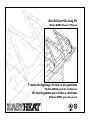 1
1
-
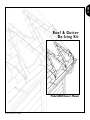 2
2
-
 3
3
-
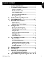 4
4
-
 5
5
-
 6
6
-
 7
7
-
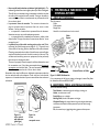 8
8
-
 9
9
-
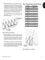 10
10
-
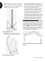 11
11
-
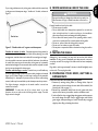 12
12
-
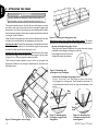 13
13
-
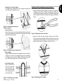 14
14
-
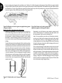 15
15
-
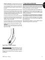 16
16
-
 17
17
-
 18
18
-
 19
19
-
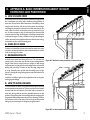 20
20
-
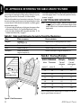 21
21
-
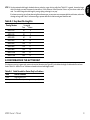 22
22
-
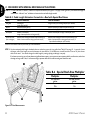 23
23
-
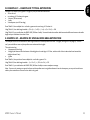 24
24
-
 25
25
-
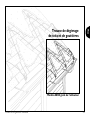 26
26
-
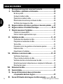 27
27
-
 28
28
-
 29
29
-
 30
30
-
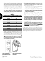 31
31
-
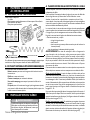 32
32
-
 33
33
-
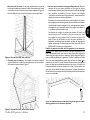 34
34
-
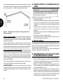 35
35
-
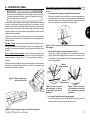 36
36
-
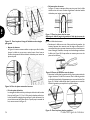 37
37
-
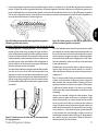 38
38
-
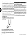 39
39
-
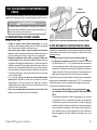 40
40
-
 41
41
-
 42
42
-
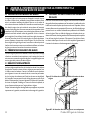 43
43
-
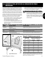 44
44
-
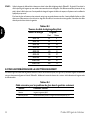 45
45
-
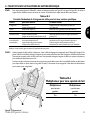 46
46
-
 47
47
-
 48
48
-
 49
49
-
 50
50
-
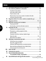 51
51
-
 52
52
-
 53
53
-
 54
54
-
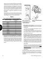 55
55
-
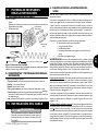 56
56
-
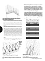 57
57
-
 58
58
-
 59
59
-
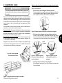 60
60
-
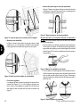 61
61
-
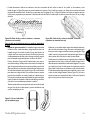 62
62
-
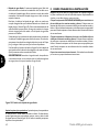 63
63
-
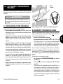 64
64
-
 65
65
-
 66
66
-
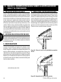 67
67
-
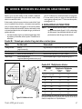 68
68
-
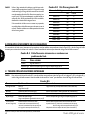 69
69
-
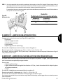 70
70
-
 71
71


EasyHeat ADKS-1000 Manuel utilisateur
- Taper
- Manuel utilisateur
dans d''autres langues
- English: EasyHeat ADKS-1000 User manual
- español: EasyHeat ADKS-1000 Manual de usuario