
Operating Instructions
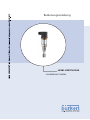
LEVEL SWITCH 8110
- contactless electronic switch

2
Contents
LEVEL SWITCH 8110 • - contactless electronic switch
41765-EN-140211
Contents
1 About this document
1.1 Function ........................................................................................................................... 3
1.2 Target group ..................................................................................................................... 3
1.3 Symbolism used ............................................................................................................... 3
2 For your safety
2.1 Authorised personnel ....................................................................................................... 4
2.2 Appropriate use ................................................................................................................ 4
2.3 Warning about incorrect use ............................................................................................. 4
2.4 General safety instructions ............................................................................................... 4
2.5 Safety label on the instrument .......................................................................................... 5
2.6 CE conformity ................................................................................................................... 5
3 Product description
3.1 Conguration .................................................................................................................... 6
3.2 Principle of operation........................................................................................................ 6
3.3 Adjustment ....................................................................................................................... 7
3.4 Storage and transport....................................................................................................... 7
4 Mounting
4.1 General instructions ......................................................................................................... 9
4.2 Mounting instructions ..................................................................................................... 11
5 Connecting to power supply
5.1 Preparing the connection ............................................................................................... 13
5.2 Wiring plan ..................................................................................................................... 13
6 Setup
6.1 Indication of the switching status .................................................................................... 17
6.2 Simulation ...................................................................................................................... 17
6.3 Function chart ................................................................................................................ 18
7 Maintenanceandfaultrectication
7.1 Maintenance .................................................................................................................. 19
7.2 Rectify faults ................................................................................................................... 19
8 Dismounting
8.1 Dismounting steps.......................................................................................................... 20
8.2 Disposal ......................................................................................................................... 20
9 Supplement
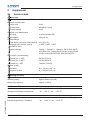
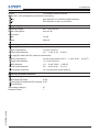
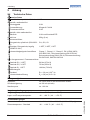
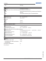
9.1 Technical data ................................................................................................................ 21
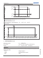
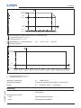
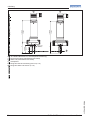
9.2 Dimensions .................................................................................................................... 24
Editing status: 2014-02-11

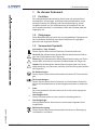
3
1 About this document
LEVEL SWITCH 8110 • - contactless electronic switch
41765-EN-140211
1 About this document
1.1 Function
This operating instructions manual provides all the information you
need for mounting, connection and setup as well as important instruc-
tionsformaintenanceandfaultrectication.Pleasereadthisinforma-
tion before putting the instrument into operation and keep this manual
accessible in the immediate vicinity of the device.
1.2 Target group
This operating instructions manual is directed to trained specialist
personnel. The contents of this manual should be made available to
these personnel and put into practice by them.
1.3 Symbolism used
Information, tip, note
This symbol indicates helpful additional information.
Caution: If this warning is ignored, faults or malfunctions can result.
Warning: If this warning is ignored, injury to persons and/or serious
damage to the instrument can result.
Danger: If this warning is ignored, serious injury to persons and/or
destruction of the instrument can result.
Ex applications
This symbol indicates special instructions for Ex applications.
SIL applications
This symbol indicates instructions for functional safety which must be
particularly taken into account for safety-relevant applications.
•
List
The dot set in front indicates a list with no implied sequence.
→
Action
This arrow indicates a single action.
1 Sequence of actions
Numbers set in front indicate successive steps in a procedure.
Battery disposal
This symbol indicates special information about the disposal of bat-
teries and accumulators.

4
2 For your safety
LEVEL SWITCH 8110 • - contactless electronic switch
41765-EN-140211
2 For your safety
2.1 Authorised personnel
All operations described in this operating instructions manual must
be carried out only by trained specialist personnel authorised by the
plant operator.
During work on and with the device the required personal protective
equipment must always be worn.
2.2 Appropriate use
The LEVEL SWITCH 8110 is a sensor for point level detection.
Youcannddetailedinformationabouttheareaofapplicationin
chapter "Product description".
Operational reliability is ensured only if the instrument is properly
usedaccordingtothespecicationsintheoperatinginstructions
manual as well as possible supplementary instructions.
For safety and warranty reasons, any invasive work on the device
beyond that described in the operating instructions manual may be
carried out only by personnel authorised by the manufacturer. Arbi-
traryconversionsormodicationsareexplicitlyforbidden.
2.3 Warning about incorrect use
Inappropriate or incorrect use of the instrument can give rise to
application-specichazards,e.g.vesseloverllordamagetosystem
components through incorrect mounting or adjustment.
2.4 General safety instructions
This is a state-of-the-art instrument complying with all prevailing
regulations and guidelines. The instrument must only be operated in a
technicallyawlessandreliablecondition.Theoperatorisresponsible
for the trouble-free operation of the instrument.
During the entire duration of use, the user is obliged to determine the
compliance of the necessary occupational safety measures with the
current valid rules and regulations and also take note of new regula-
tions.
The safety instructions in this operating instructions manual, the na-
tional installation standards as well as the valid safety regulations and
accident prevention rules must be observed by the user.
For safety and warranty reasons, any invasive work on the device
beyond that described in the operating instructions manual may be
carried out only by personnel authorised by the manufacturer. Arbi-
traryconversionsormodicationsareexplicitlyforbidden.
The safety approval markings and safety tips on the device must also
be observed.

5
2 For your safety
LEVEL SWITCH 8110 • - contactless electronic switch
41765-EN-140211
2.5 Safety label on the instrument
The safety approval markings and safety tips on the device must be
observed.
2.6 CE conformity
ThedevicefulllsthelegalrequirementsoftheapplicableECguide-
lines.ByaxingtheCEmarking,weconrmsuccessfultestingofthe
product.
YoucanndtheCECerticateofConformityinthedownloadsection
of our homepage.

6
3 Product description
LEVEL SWITCH 8110 • - contactless electronic switch
41765-EN-140211
3 Product description
3.1 Conguration
The scope of delivery encompasses:
•
LEVEL SWITCH 8110 point level switch
•
Test magnet
•
Documentation
– this operating instructions manual
– ifnecessary,certicates
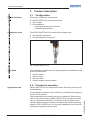
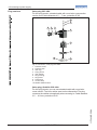
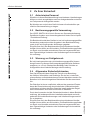
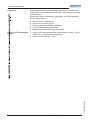
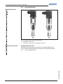
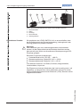
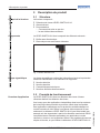
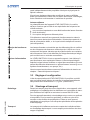
The LEVEL SWITCH 8110 consists of the components:
•
Housing with electronics
•
Processttingwithtuningfork
Fig. 1: LEVEL SWITCH 8110
Thenameplatecontainsthemostimportantdataforidenticationand
use of the instrument:
•
Article number
•
Serial number
•
Technical data
•
Article numbers, documentation
3.2 Principle of operation
LEVEL SWITCH 8110 is a point level sensor with tuning fork for point
level detection.
It is designed for industrial use in all areas of process technology and
can be used in liquids.
Typicalapplicationsareoverllanddryrunprotection.Withatuning
fork of only 38 mm length, LEVEL SWITCH 8110 can be also mount-
ed e.g. in pipelines from DN 25. The small tuning fork allows use in
vessels, tanks and pipes. Thanks to its simple and robust measuring
system,LEVELSWITCH8110isvirtuallyunaectedbythechemical
and physical properties of the liquid.
Scope of delivery
Constituent par
ts
T
ype plate
Application area

7
3 Product description
LEVEL SWITCH 8110 • - contactless electronic switch
41765-EN-140211
Itfunctionsevenunderdicultconditionssuchasturbulence,airbub-
bles, foam generation, buildup, strong external vibration or changing
products.
Function monitoring
The electronics module of LEVEL SWITCH 8110 continuously moni-
tors via frequency evaluation the following criteria:
•
Strong corrosion or damage on the tuning fork
•
Loss of vibration
•
Linebreaktothepiezodrive
If a malfunction is detected or in case of power failure, the electronics
takesonadenedswitchingcondition,i.e.thecontactlesselectronic
switch opens (safe condition).
Thetuningforkispiezoelectricallyenergisedandvibratesatitsme-
chanicalresonancefrequencyofapprox.1100Hz.Whenthetuning
fork is submerged in the product, the frequency changes. This change
is detected by the integrated electronics module and converted into a
switching command.
LEVEL SWITCH 8110 is a compact instrument, i.e. it can be oper-
ated without external evaluation system. The integrated electronics
evaluates the level signal and outputs a switching signal. With this
switching signal, a connected device can be operated directly (e.g. a
warning system, a pump etc.).
Thedataforpowersupplyarespeciedinchapter"Technical data".
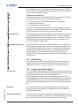
3.3 Adjustment
The switching status of LEVEL SWITCH 8110 can be checked with
closed housing (signal lamp). Products with a density > 0.7 g/cm³
(0.025 lbs/in³) can be detected.
3.4 Storage and transport
Your instrument was protected by packaging during transport. Its
capacity to handle normal loads during transport is assured by a test
based on ISO 4180.
The packaging of standard instruments consists of environment-
friendly, recyclable cardboard. For special versions, PE foam or PE
foil is also used. Dispose of the packaging material via specialised
recycling companies.
Transport must be carried out in due consideration of the notes on the
transport packaging. Nonobservance of these instructions can cause
damage to the device.
The delivery must be checked for completeness and possible transit
damage immediately at receipt. Ascertained transit damage or con-
cealed defects must be appropriately dealt with.
Functional principle
V
oltage supply
Packaging
Transport
Transport inspection

8
3 Product description
LEVEL SWITCH 8110 • - contactless electronic switch
41765-EN-140211
Up to the time of installation, the packages must be left closed and
stored according to the orientation and storage markings on the
outside.
Unless otherwise indicated, the packages must be stored only under
the following conditions:
•
Not in the open
•
Dry and dust free
•
Not exposed to corrosive media
•
Protected against solar radiation
•
Avoiding mechanical shock and vibration
•
Storage and transport temperature see chapter "Supplement -
Technical data - Ambient conditions"
•
Relative humidity 20 … 85 %
Storage
Storage and transport
temperature

9
4 Mounting
LEVEL SWITCH 8110 • - contactless electronic switch
41765-EN-140211
4 Mounting
4.1 General instructions
Make sure that all parts of the instrument coming in direct contact
with the process, especially the sensor element, process seal and
processtting,aresuitablefortheexistingprocessconditions,such
as process pressure, process temperature as well as the chemical
properties of the medium.
Youcanndthespecicationsinchapter"Technical data" and on the
nameplate.
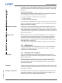
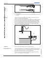
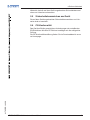
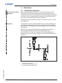
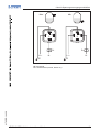
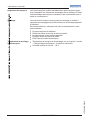
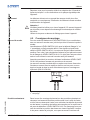
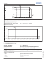
In general, LEVEL SWITCH 8110 can be installed in any position. The
instrument only has to be mounted in such a way that the tuning fork
is at the height of the desired switching point.
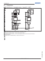
Keep in mind that the swichting point can vary dependent on the
installation position.
The switching point refers to the medium water (1 g/cm³/0.036 lbs/
in³). Please keep in mind that the switching point of the instrument
shiftswhenthemediumhasadensitydieringfromwater.
2
3
1
11 mm
(0.43")
34 mm
(1.34")
Fig. 2: Vertical mounting
1 Switching point in water
2 Switching point with lower density
3 Switching point with higher density
Suitability for the process
conditions
Switching point

10
4 Mounting
LEVEL SWITCH 8110 • - contactless electronic switch
41765-EN-140211
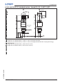
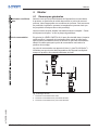
2
1
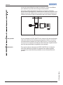
Fig. 3: Horizontal mounting
1 Switching point
2 Switching point (recommended mounting position, particularly for adhesive
products)
Use the recommended cables (see chapter "Connecting to power
supply") and tighten the cable gland.
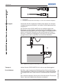
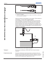
You can give your LEVEL SWITCH 8110 additional protection against
moisture penetration by leading the connection cable downward in
front of the cable entry. Rain and condensation water can thus drain
o.Thisappliesmainlytooutdoormountingaswellasinstallationin
areas where high humidity is expected (e.g. through cleaning pro-
cesses) or on cooled or heated vessels.
Fig. 4: Measures against moisture penetration
Do not hold LEVEL SWITCH 8110 on the tuning fork.
Theprocessttingmustbesealedifthereisgaugeorlowpressurein
the vessel. Before use, check if the seal material is resistant against
the measured product and the process temperature.
Themax.permissiblepressureisspeciedinchapter"Technical
data" or on the type label of the sensor.
Moisture
T
r
ansport
Pressure/Vacuum

11
4 Mounting
LEVEL SWITCH 8110 • - contactless electronic switch
41765-EN-140211
The vibrating level switch is a measuring instrument and must be
treated accordingly. Bending the vibrating element will destroy the
instrument.
Warning:
The housing must not be used to screw the instrument in! Applying
tightening force can damage internal parts of the housing.
Use the hexagon above the thread for screwing in.
4.2 Mounting instructions
For threaded versions of LEVEL SWITCH 8110 in combination with a
mounting boss with O-ring in front and welding marking.
LEVELSWITCH8110withthreadsizes¾"and1"haveadened
thread runout. This means that every LEVEL SWITCH 8110 is in the
same position after being screwed in. Remove therefore the supplied
atsealfromthethreadofLEVELSWITCH8110.Thisatsealisnot
requiredwhenusingaweldedsocketwithfront-ushseal.
Before welding, unscrew LEVEL SWITCH 8110 and remove the rub-
ber ring from the welded socket.
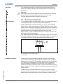
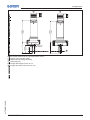
Theweldedsocketisprovidedwithamarking(notch).Forhorizontal
mounting, weld the socket with the notch facing upward or downward;
inpipelines(DN25toDN50)alignedwiththedirectionofow.
1
Fig. 5: Marking on the welded socket
1 Marking
Incaseofhorizontalmountinginadhesiveandviscousproducts,
the surfaces of the tuning fork should be vertical in order to reduce
buildup on the tuning fork. The position of the tuning fork is indicated
by a marking on the hexagon of LEVEL SWITCH 8110. With this,
you can check the position of the tuning fork when screwing it in.
When the hexagon touches the seal, the thread can still be turned by
approx.halfaturn.Thisissucienttoreachtherecommendedinstal-
lation position.
In adhesive and viscous products, the surfaces of the tuning fork
should protrude into the vessel to avoid buildup. Therefore sockets for
angesandmountingsbossesshouldnotexceedacertainlength.
Handling
Welded socket
Adhesive products

12
4 Mounting
LEVEL SWITCH 8110 • - contactless electronic switch
41765-EN-140211
30 mm
(1.18")
Fig. 6: Adhesive products
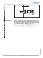
IfLEVELSWITCH8110ismountedinthellingstream,unwanted
false measurement signals can be generated. For this reason, mount
LEVEL SWITCH 8110 at a position in the vessel where no disturbanc-
es,e.g.fromllingopenings,agitators,etc.,canoccur.
To make sure the tuning fork of LEVEL SWITCH 8110 generates as
littleresistanceaspossibletoproductow,mountthesensorsothat
the surfaces are parallel to the product movement.
Inowingmedium
Flows

13
5 Connecting to power supply
LEVEL SWITCH 8110 • - contactless electronic switch
41765-EN-140211
5 Connecting to power supply
5.1 Preparing the connection
Always keep in mind the following safety instructions:
•
Connect only in the complete absence of line voltage
The instrument is connected with standard two-wire cable without
screen. If electromagnetic interference is expected which is above the
test values of EN 61326 for industrial areas, screened cable should
be used.
Use cable with round cross section. Depending on the plug connec-
tion, you have to select the outer diameter of the cable respectively so
thatthesealeectofthecableglandisensured.
•
Valve plug ISO 4400, ø 4.5 … 7 mm
•
Valve plug ISO 4400 with IDC crimping technology, ø 5.5 … 8 mm
Use cable with a round wire cross section and tighten the cable gland.
When mounting outdoors, on cooled vessels or in moist areas in
which cleaning is made with steam or high pressure, the sealing of
the cable gland is very important.
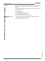
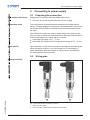
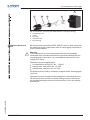
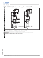
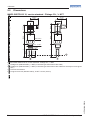
5.2 Wiring plan
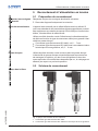
2
1 2
Fig. 7: Overview of the connection versions
1 Valve plug ISO 4400
2 Valve plug ISO 4400 with IDC method of termination
Note safety instructions
Connection cable
Cable glands
Housing overview

14
5 Connecting to power supply
LEVEL SWITCH 8110 • - contactless electronic switch
41765-EN-140211
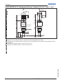
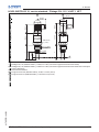
Valve plug ISO 4400
For this plug version, standard cable with round wire cross-section
can be used. Cable diameter 4.5 … 7 mm, protection IP 65.
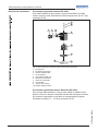
1
4
5
6
7
8
9
10
2 3
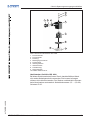
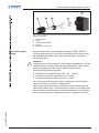
Fig. 8: Connection, valve plug ISO 4400
1 Pressure screw
2 Pressure disc
3 Seal ring
4 Fixing screw
5 Seal washer
6 Plug housing
7 Plug insert
8 Proleseal
9 Control lamp
10 LEVEL SWITCH 8110
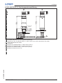
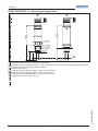
Valve plug, QuickOn ISO 4400
For this plug version you can use standard cable with round wire
cross-section. The inner cables must not be dismantled. The plug
connects the cables automatically when screwing in. Cable diameter
3.5 … 6.5 mm, protection IP 65.
Plug versions

15
5 Connecting to power supply
LEVEL SWITCH 8110 • - contactless electronic switch
41765-EN-140211
1 2 3 4
5
Fig. 9: Connection, valve plug ISO 4400 with IDC crimping technology
1 Compression nut
2 Cable
3 Seal ring
4 Terminal insert
5 Plug housing
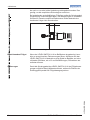
We recommend connecting LEVEL SWITCH 8110 in such a way that
the switching circuit is open when there is a level signal, line break or
failure (safe condition).
Warning:
The instrument must not be operated without an intermediately
connected load, because the electronics would be destroyed if con-
nected directly to the mains. It is not suitable for connection to low
voltage PLC inputs.
Examples for typical applications:
•
Loadresistanceat24VDC:88…1800Ω
•
Rated power, relay 253 V AC: > 2.5 VA
•
Rated power, relay 24 V AC: > 0.5 VA
For direct control of relays, contactors, magnet valves, warning lights,
horns etc.
Domestic current is temporarily lowered below 1 mA after switching
otheloadsothatcontactors,whoseholdingcurrentislowerthan
the constant domestic current of the electronics (3 mA), are reliably
switchedo.
Contactless electronic
switch

16
5 Connecting to power supply
LEVEL SWITCH 8110 • - contactless electronic switch
41765-EN-140211
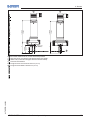
R
L
R
L
3
2 1
3
2 1
N- L1+ L1+ N-
Max. Min.
PE
PE
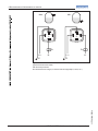
Fig. 10: Wiring plan, contactless electronic switch with valve plug ISO 4400
PE Protective ground
RL Load resistance (contactor, relay, etc.)

17
6 Setup
LEVEL SWITCH 8110 • - contactless electronic switch
41765-EN-140211
6 Setup
6.1 Indication of the switching status
The switching status of the electronics can be checked via the signal
lamps (LEDs) integrated in the upper part of the housing.
The signal lamps have the following meaning:
•
Green lights - voltage supply connected
•
Yellow lights - vibrating element covered
•
Redlightsbriey-functiontestduringinstrumentstart(for0.5s)
•
Red lights - shortcircuit or overload in the load circuit (sensor
output high-impedance)
•
Redashes-Erroronthevibratingelementortheelectronics
(sensor output high impedance)
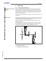
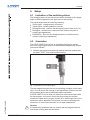
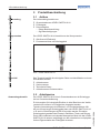
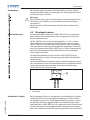
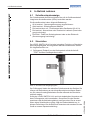
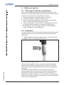
6.2 Simulation
The LEVEL SWITCH 8110 has an integrated function for simula-
tion of the output signal which can be activated magnetically. Please
proceed as follows:
→
Hold the test magnet (accessory) against the circle symbol with
the label "TEST" on the instrument housing
Fig. 11: Simulation of the output signal
The test magnet changes the current switching condition of the instru-
ment. You can check the change on the signal lamp. Please note that
all connected device are activated during the simulation.
If LEVEL SWITCH 8110 does not switch over after several tests with
the test magnet, you have to check the plug connection and the
connection cable and try it again. If there is no switching function, the
electronics will be defective. In this case you have to exchange the
electronics or return the instrument to our repair department.
Caution:
It is absolutely necessary that you remove the test magnet from the
instrument housing after the simulation.

18
6 Setup
LEVEL SWITCH 8110 • - contactless electronic switch
41765-EN-140211
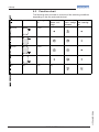
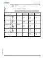
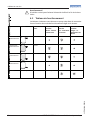
6.3 Function chart
The following chart provides an overview of the switching conditions
depending on the set mode and the level.
Level Switching sta-
tus
Control lamp
Yellow - cov-
erage
Control lamp
Green - voltage
indication
Control lamp
Red - fault sig-
nal
Mode max.
closed
Mode max. open
Mode min. closed
Mode min. open
Fault any open any

19
7Maintenanceandfaultrectication
LEVEL SWITCH 8110 • - contactless electronic switch
41765-EN-140211
7 Maintenanceandfaultrectication
7.1 Maintenance
If the instrument is used properly, no special maintenance is required
in normal operation.
7.2 Rectify faults
The operator of the system is responsible for taking suitable meas-
ures to rectify faults.
LEVELSWITCH8110oersmaximumreliability.Nevertheless,faults
can occur during operation. These may be caused by the following,
e.g.:
•
Sensor
•
Process
•
Voltage supply
•
Signal processing
Therstmeasuretobetakenistochecktheoutputsignal.Inmany
cases,thecausescanbedeterminedthiswayandthefaultsrectied.
Error Cause Rectication
Green signal
lampo
Voltage supply in-
terrupted.
Check the voltage supply and the ca-
ble connection
Electronics de-
fective
Exchange the instrument or send it in
for repair
Red signal lamp
lights (switching
output high-im-
pedance)
Error with the
electrical con-
nection
Connect the instrument according to
the wiring plan
Shortcircuit or
overload
Check the electrical connection
Red signal lamp
ashes(switching
output high-im-
pedance)
Virbating fre-
quency out of
specication
Check the vibrating element on build-
up and remove it
Buildup on the vi-
brating element
Check the vibrating element and
the sensor if there is buildup and re-
move it
Vibrating element
damaged
Check if the vibrating element is dam-
age or extremely corroded
Depending on the reason for the fault and the measures taken, the
steps described in chapter "Set up" may have to be carried out again.
Reaction when malfunc-
tions occur
F
ailur
e reasons
Faultrectication
Checking the switching
signal
Reaction after fault recti-
cation

20
8 Dismounting
LEVEL SWITCH 8110 • - contactless electronic switch
41765-EN-140211
8 Dismounting
8.1 Dismounting steps
Warning:
Before dismounting, be aware of dangerous process conditions such
as e.g. pressure in the vessel, high temperatures, corrosive or toxic
products etc.
Take note of chapters "Mounting" and "Connecting to power supply"
and carry out the listed steps in reverse order.
8.2 Disposal
The instrument consists of materials which can be recycled by spe-
cialised recycling companies. We use recyclable materials and have
designed the parts to be easily separable.
WEEE directive 2002/96/EG
This instrument is not subject to the WEEE directive 2002/96/EG and
the respective national laws. Pass the instrument directly on to a spe-
cialised recycling company and do not use the municipal collecting
points. These may be used only for privately used products according
to the WEEE directive.
Correctdisposalavoidsnegativeeectsonhumansandtheenviron-
ment and ensures recycling of useful raw materials.
Materials: see chapter "Technical data"
If you have no way to dispose of the old instrument properly, please
contact us concerning return and disposal.
La page est en cours de chargement...
La page est en cours de chargement...
La page est en cours de chargement...
La page est en cours de chargement...
La page est en cours de chargement...
La page est en cours de chargement...
La page est en cours de chargement...
La page est en cours de chargement...
La page est en cours de chargement...
La page est en cours de chargement...
La page est en cours de chargement...
La page est en cours de chargement...
La page est en cours de chargement...
La page est en cours de chargement...
La page est en cours de chargement...
La page est en cours de chargement...
La page est en cours de chargement...
La page est en cours de chargement...
La page est en cours de chargement...
La page est en cours de chargement...
La page est en cours de chargement...
La page est en cours de chargement...
La page est en cours de chargement...
La page est en cours de chargement...
La page est en cours de chargement...
La page est en cours de chargement...
La page est en cours de chargement...
La page est en cours de chargement...
La page est en cours de chargement...
La page est en cours de chargement...
La page est en cours de chargement...
La page est en cours de chargement...
La page est en cours de chargement...
La page est en cours de chargement...
La page est en cours de chargement...
La page est en cours de chargement...
La page est en cours de chargement...
La page est en cours de chargement...
La page est en cours de chargement...
La page est en cours de chargement...
La page est en cours de chargement...
La page est en cours de chargement...
La page est en cours de chargement...
La page est en cours de chargement...
La page est en cours de chargement...
La page est en cours de chargement...
La page est en cours de chargement...
La page est en cours de chargement...
La page est en cours de chargement...
La page est en cours de chargement...
La page est en cours de chargement...
La page est en cours de chargement...
La page est en cours de chargement...
La page est en cours de chargement...
La page est en cours de chargement...
La page est en cours de chargement...
La page est en cours de chargement...
La page est en cours de chargement...
La page est en cours de chargement...
La page est en cours de chargement...
La page est en cours de chargement...
La page est en cours de chargement...
La page est en cours de chargement...
La page est en cours de chargement...
La page est en cours de chargement...
La page est en cours de chargement...
La page est en cours de chargement...
La page est en cours de chargement...
-
 1
1
-
 2
2
-
 3
3
-
 4
4
-
 5
5
-
 6
6
-
 7
7
-
 8
8
-
 9
9
-
 10
10
-
 11
11
-
 12
12
-
 13
13
-
 14
14
-
 15
15
-
 16
16
-
 17
17
-
 18
18
-
 19
19
-
 20
20
-
 21
21
-
 22
22
-
 23
23
-
 24
24
-
 25
25
-
 26
26
-
 27
27
-
 28
28
-
 29
29
-
 30
30
-
 31
31
-
 32
32
-
 33
33
-
 34
34
-
 35
35
-
 36
36
-
 37
37
-
 38
38
-
 39
39
-
 40
40
-
 41
41
-
 42
42
-
 43
43
-
 44
44
-
 45
45
-
 46
46
-
 47
47
-
 48
48
-
 49
49
-
 50
50
-
 51
51
-
 52
52
-
 53
53
-
 54
54
-
 55
55
-
 56
56
-
 57
57
-
 58
58
-
 59
59
-
 60
60
-
 61
61
-
 62
62
-
 63
63
-
 64
64
-
 65
65
-
 66
66
-
 67
67
-
 68
68
-
 69
69
-
 70
70
-
 71
71
-
 72
72
-
 73
73
-
 74
74
-
 75
75
-
 76
76
-
 77
77
-
 78
78
-
 79
79
-
 80
80
-
 81
81
-
 82
82
-
 83
83
-
 84
84
-
 85
85
-
 86
86
-
 87
87
-
 88
88


Burkert LEVEL SWITCH 8110 Mode d'emploi
- Taper
- Mode d'emploi
- Ce manuel convient également à
dans d''autres langues
Autres documents
-
SICK LFC Mode d'emploi
-
-
-
-
-
 Vega VEGAWAVE 61 Mode d'emploi
-
 LITTLE BALANCE 8107 PONTON Le manuel du propriétaire
-
GN Netcom GN 8110 USBxp Manuel utilisateur
-
Dura Heat DuraHeat DFA-170C Manuel utilisateur
-
Jabra GN8110 Le manuel du propriétaire

