ETC Source 4WRD Installation and User Manual
- Taper
- Installation and User Manual

Source 4WRD
PAR and PARNel Fixture Bodies
Installation and User Manual
Part Number: 7067M1220 Rev C
Released: 2020-02


Table of Contents
Source 4WRD Installation and User Manual i
Introduction
1
Help from ETC Technical Services
2
Safety
3
Install the Fixture
8
Wire the power connector(if needed)
8
Install the Source 4WRDLED
8
Attach C-clamp and Safety Cable
10
Connect Cables
11
Configure the Fixture
14
RDMValues
14
Set Up the Fixture
15
Set the Angle within the Yoke
15
Use the Accessory Holder
15
Loosen the Z-adjustmentKnob
15
Adjust the Focus Knob
(PARNelFixturesOnly)
16


Source 4WRD Installation and User Manual 1
Introduction
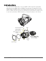
Use the Source 4WRDLED or Source 4WRD II LED (supplied separately)
with the Source 4WRD PAR or PARNel Fixture Body to create the Source
4WRD PAR or PARNel fixture. The fixture produces about 20% more flux
than a 750W long-life Source Four PAR while consuming less power, and
it can be line-dimmed, DMX-dimmed, or dimmed locally on the fixture.
Yoke
Source 4WRD LED
or Source 4WRD II LED
(not included)
Lens
rotation
ring
Tabs
Lens
Color frame
Color frame
holder
Color frame
retaining clip
Yoke locking knob

2 Source 4WRD Installation and User Manual
Help from ETC Technical Services
If you are having difficulties and your problem is not addressed by this
document, try the ETC support website at support.etcconnect.com or the
main ETC website at etcconnect.com. If none of these resources are
sufficient, contact ETC Technical Services directly at one of the offices
identified below. Emergency service is available from all ETC offices
outside of normal business hours.
When calling for help, take these steps first:
•
Prepare a detailed description of the problem
•
Go near the equipment for troubleshooting
•
Find your notification number if you have called in previously
Americas United Kingdom
ETC, Inc. ETC Ltd
Technical Services Department Technical Services Department
3031 Pleasant View Road 26-28 Victoria Industrial Estate
Middleton, WI 53562 Victoria Road,
800-775-4382 (USA, toll-free) London W3 6UU England
+1-608 831-4116 +44 (0)20 8896 1000
service@etcconnect.com techservltd@etcconnect.com
Asia Germany
ETCAsia ETC GmbH
Technical Services Department Technical Services Department
Room 1801, 18/F Ohmstrasse 3
Tower 1, Phase 1 Enterprise Square 83607 Holzkirchen, Germany
9 Sheung Yuet Road +49 (80 24) 47 00-0
Kowloon Bay, Kowloon, Hong Kong techserv-hoki@etcconnect.com
+852 2799 1220
techservasia@etcconnect.com
France
ETC France
Zone Urbaparc -
Bâtiment E
6 Boulevard de la Libération
Saint-Denis, 93200
+33 1 4243 3535
techservltd@etcconnect.com

Source 4WRD Installation and User Manual 3
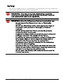
Safety
The Source 4WRD fixture is intended for professional use only. Read the
entire manual before using this equipment.
WARNING: This fixture must be installed by a qualified
electrician in accordance with all national and local electrical
and construction codes and regulations.
WARNING: Note the following safety warnings before use:
•
Do not mount the fixture on or near a flammable
surface.
•
Do not use this fixture with a damaged power lead. If
the power lead (cord set) is damaged, it must be
replaced.
•
Mount and support the fixture only by the primary
suspension holes in the yoke.
•
Suspend the fixture from a suitable structure using only
hardware rated for the weight of the fixture.
•
In addition to primary suspension, attach a safety cable
(ETC Model 400SC or other approved safety cable or
device) to the fixture housing. An appropriate
attachment point (hole) is provided in the protruding
tab on the fixture housing.
•
Disconnect the unit from power and DMX and allow the
fixture to cool before removing or installing accessories,
and before all cleaning and maintenance.
•
Do not cover the fixture with material that is used for
thermal insulation.

4 Source 4WRD Installation and User Manual
AVERTISSEMENT : Prendre connaissance des avertissements
de sécurité suivants avant toute utilisation :
•
Ne pas installer le projecteur sur ou à côté d’une surface
inflammable.
•
Ne pas utiliser ce projecteur avec un cordon
d’alimentation endommagé. Si le cordon d’alimentation
(câble) est abîmé, il doit être remplacé.
•
Installer et accrocher le projecteur uniquement par les
trous de fixation principaux de la lyre.
•
Accrocher le projecteur à une structure convenable en
utilisant seulement du matériel adapté au poids du
projecteur.
•
En plus de l'accroche principale, fixer une élingue de
sécurité (modèle ETC400SC ou autre câble/dispositif de
sécurité certifié) au corps du projecteur. Un point
d’accroche (trou) approprié est prévu dans la patte qui
ressort du boîtier du projecteur.
•
Déconnecter l’alimentation et le DMX et laisser le
projecteur refroidir avant d’enlever ou installer
l'optique découpe ou les autres adaptateurs, et avant
tout nettoyage et entretien.
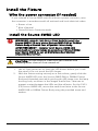
WARNING: RISK OF FIRE OR ELECTRIC SHOCK! Installing the
Source 4WRDLED retrofit kit requires knowledge of luminaire
electrical systems. If you are not qualified, do not attempt
installation. Contact a qualified electrician.
AVERTISSEMENT : RISQUE D'INCENDIE OU DE DÉCHARGE
ÉLECTRIQUE! Installer le nécessaire de conversion Source
4WRDLED nécessite une connaissance des systèmes
électriques de projecteurs. Si vous n’êtes pas qualifié, ne
tentez pas l’installation. Faire appel à un électricien qualifié.
WARNING: RISK OF FIRE OR ELECTRIC SHOCK! Install this kit
only onto luminaires that have the construction features and
dimensions shown in the images in this document and where
the input rating of the retrofit kit does not exceed the input
rating of the luminaire.
AVERTISSEMENT : RISQUE D'INCENDIE OU DE DÉCHARGE
ÉLECTRIQUE! N’installer ce kit que sur les projecteurs qui ont
les caractéristiques de construction et les dimensions
indiquées sur les images de ce document et où la puissance
électrique nécessaire à la conversion n’excède pas la puissance
maximale du projecteur.

Source 4WRD Installation and User Manual 5
WARNING: Note the following safety warnings before use:
•
The Source 4WRD LED is not user serviceable. Field
modification of the Source 4WRD LED will void your ETC
warranty.
•
Do not use the Source 4WRD fixture below 5°C (41°F).
•
Minimum storage temperature is 5°C (41°F). When the
fixture has been stored or transported in cold
temperatures, allow it to warm to room temperature
for a minimum of 1hour before applying power.
Applying power to a cold fixture will cause damage to
the fixture and void the ETCwarranty.
•
Do not use this fixture if a glass lens is deeply scratched
or cracked. Damaged lenses must be replaced.
•
To prevent wiring damage, or abrasion, do not expose
wiring to edges of sheet metal or other sharp objects.
•
Use the Source 4WRD fixture in dry locations only,
where humidity does not exceed 90 percent (non-
condensing). These fixtures are not intended for
outdoor use.
•
Do not make or alter any open holes in an enclosure of
wiring or electrical components during kit installation.
Note:
THE RETROFIT KIT IS ACCEPTABLE AS A COMPONENT OF A
LUMINAIRE WHERE THE SUITABILITY OF THE COMBINATION SHALL
BE DETERMINED BY AUTHORITIES HAVING JURISDICTION.

6 Source 4WRD Installation and User Manual
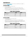
Specifications
For full product specifications, see the Source 4WRD PAR or PARNel
datasheet at etcconnect.com.
Electrical (120V)
•
114–125 VAC 60 Hz power input
•
150 W draw at full
•
Recommended 2 fixtures per dimmed circuit (D20 module)
•
Maximum of 14 fixtures per non-dimmed circuit (R20 module)
•
If using in DMX mode: Connect fixture to relay, constant power, or
dimmer with regulation off and parked at full
Typical Power Consumption
Mode Power Current
Idle:DMXMode 1.2W .03A
Idle: ACMode 0W 0 A
Full Intensity 150W 1.26A
Electrical (230V)
•
209–252 VAC 47–53 Hz power input
•
175 W draw at full
•
Recommended 2 fixtures per dimmed circuit (ED15 module)
•
Maximum of 6 fixtures per non-dimmed circuit (ER15AFR module)
•
If using in DMX mode: Connect fixture to relay, constant power, or
dimmer with regulation off and parked at full
Typical Power Consumption
Mode Power Current
Idle:DMXMode 3.7W .05A
Idle: ACMode 0W 0 A
Full Intensity 175W .75A

Source 4WRD Installation and User Manual 7
Environment
•
Ambient operating temperature: 5°C–50°C (41°F–122°F)
•
Minimum storage temperature: 5°C (41°F)
•
Maximum recommended ambient operating temperature:Ta=50°C
(122°F)
•
Maximum anticipated external surface temperature: Tmax=63°C
(145°F) at Ta=50°C (122°F)
•
External Temperature (steady state achieved) at 25°C (77°F)
ambient: 38°C (100°F)
Weight
•
Source 4WRD PAR fixture body only: 2.83kg (6.25lb)
•
Assembled Source 4WRD PAR fixture: 4.53kg (9.98lb)
•
Source 4WRD PARNel fixture body only: 3.49kg (7.70lb)
•
Assembled Source 4WRD PARNel fixture: 5.18kg (11.43lb)

8 Source 4WRD Installation and User Manual
Install the Fixture
Wire the power connector(if needed)
If you ordered a Source 4WRD retrofit without a power connector, wire
the connector in accordance with all national and local electrical codes:
•
Brown = Live
•
Blue = Neutral
•
Green/Yellow = Protective earth
Install the Source 4WRDLED
WARNING: RISK OF FIRE OR ELECTRIC SHOCK! Install the
Source 4WRDLED only onto a Source 4WRD PAR or PARNel
Fixture Body or Source Four ellipsoidal fixture body.
AVERTISSEMENT : Installer le kit Source 4WRDLED
seulement sur un bloc lampe de projecteur PAR ou PARNel
pour Source 4WRD ou sur un bloc lampe de projecteur
ellipsoïdal Source Four.
CAUTION:
Do not touch or clean LED optic domes with
anything other than oil-free canned air.
1. Use oil-free canned air to clean the LED domes before you install
the retrofit. Do not touch the LEDdomes.
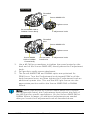
2. With the fixture resting securely on a flat surface, gently slide the
Source 4WRDLED onto the Source 4WRD PAR or PARNel Fixture
Body and threaded post while guiding the LED tower into the lamp
housing hole, as shown in the images that follow. Take care to
prevent contact between the LEDs and the reflector. For the 230V
(CE) Source 4WRDLED, secure the earth bond wire to the Source
4WRD PAR or PARNel Fixture Body using the provided screw and
washer.

Source 4WRD Installation and User Manual 9
Source 4WRD PAR or
PARNel Fixture Body
Z-adjustment knob
Tighten screw
Source 4WRD LED
Threaded
post
120 V (UL)
Source 4WRD
PAR or PARNel
Fixture Body
Z-adjustment knob
Tighten screw
Source 4WRD LED
Threaded
post
Secure earth
bond wire
230 V (CE)
3. Use a #2 Phillips screwdriver to tighten the screw located on the
back end of the Source 4WRDLED, directly above the Z-adjustment
knob.
4. Pull gently to verify secure attachment.
5. The Source 4WRD PAR and PARNel optics are optimized for
PEAKfocus. Turn the Z-adjustment knob toward PEAK until the
knob becomes loose, and then tighten the Z-adjustment knob an
additional quarter turn. This sets the LED light source into the
appropriate position within the Source 4WRD PAR or PARNel
fixture.
Note:
When used as part of a Source 4WRD retrofit on a Source
Four ellipsoidal fixture, the Z-adjustment knob adjusts the field of
the LED light for specific applications. On the Source 4WRD PAR or
PARNel fixture, however, no additional adjustments are needed
after you loosen the Z-adjustment knob as described above.

10 Source 4WRD Installation and User Manual
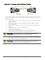
Attach C-clamp and Safety Cable
Yoke
Safety cable
attachment loop
Yoke locking
knob
Cat5 cable
strain relief
The C-clamp attaches the fixture to the mounting pipe and allows you to
adjust the position of the mounted fixture. ETC recommends using 1.5in
schedule 40 pipe.
1. Tightly fasten the C-clamp to the yoke with the provided yoke bolt
and lock washer.
2. Place the C-clamp on mounting pipe, and then tighten the pipe
bolt to secure it.
3. Loosen the C-clamp pan screw and rotate the yoke to the desired
position.
4. Tighten the pan screw to lock the fixture.
5. Connect the safety cable.
6. Tighten the C-clamp pipe bolt to 15–20 ft-lb (20–27 Nm),
approximately finger tight plus up to one-quarter turn.
CAUTION:
Do not exceed 25 ft-lb (33 Nm) while tightening
the C-clamp pipe bolt. Do not use excessive force.
7. Tighten the yoke pivot bolt to 5–10 ft-lb (6–7 Nm), approximately
finger tight plus up to one-eighth turn.
CAUTION:
Do not exceed 15 ft-lb (20 Nm) while tightening
the yoke pivot bolt. Do not use excessive force.

Source 4WRD Installation and User Manual 11
Connect Cables
You can control the fixture using AC power or DMX. Configure the fixture
to use the appropriate control method on the user interface. See
Configure the Fixture on page14
.
WARNING: Do not use or store the Source 4WRD fixture
below 5°C (41°F). When the fixture has been stored or
transported in cold temperatures, allow it to warm to room
temperature for a minimum of 1 hour before applying power.
Applying power to a cold fixture will cause damage to the
fixture and void ETC warranty.
Note:
For optimum performance, make sure that your dimmer is
out of regulated mode. See Line-dimming on the next page for
recommended dimmer settings.
Note:
Connecting both power and data from a SmartBar 1 to a
Source 4WRD fixture may cause flickering.
1. If you are using DMX control: Connect one RJ45 data cable for
data-in and one for data-thru, as needed. Use the strain relief at
the bottom of the fixture to support the data cables.
•
To order an RJ45-to-female XLR adapter, use ETC part number
W6538.
•
To order an RJ45-to-male XLR adapter, use ETC part number
W6539.
2. If you are using DMXcontrol and this is the last fixture in the line,
terminate the fixture with a 120Ohm resistor. Please contact your
ETC customer service representative to purchase ETC part number
N4086. See
Help from ETC Technical Services on page2
.
3. Connect the fixture to the power source.

12 Source 4WRD Installation and User Manual
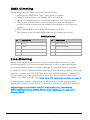
DMXDimming
When dimming via DMX, consider the following:
•
When using DMX over Cat5, use Cat5e or better.
•
Cable distance must not exceed 300 m (1000 ft).
•
Up to 32 fixtures can be connected together into a daisy chain.
•
The Source 4WRD fixture cannot be controlled via Ethernet
protocols and should not be directly connected to an Ethernet
system.
•
When DMX data is lost, the LEDemitters turn off.
•
The fixture uses a single DMXchannel for intensity control.
DMXpinout
Pin Description
1 DMX +
2 DMX -
3 Not connected
4 Not connected
Pin Description
5 Not connected
6 Not connected
7 Common (shield)
8 Not connected
Line-dimming
When line-dimming the fixture, set the parameters as shown in the
following tables to ensure that the dimmer is out of regulated mode.
(You may need to adjust dimmer settings for optimal fixture control).
In addition to the recommended settings in the following tables, you may
need to increase the SCR Off Time from the default setting. Contact ETC
for assistance in changing the SCR Off Time, or any other CEM classic,
CEM+, or CEM3 settings. See
Help from ETC Technical Services on page2
.
For the most current information on additional dimmer performance
testing for both ETC and non-ETC dimmers, please visit the ETC website:
https://support.etcconnect.com/ETC/Fixtures/Source_Four/Source_
4WRD%2F%2FSource_4WRD_PAR/Dimmer_Settings_for_Use_with_
Source_4WRD

Source 4WRD Installation and User Manual 13
Note:
When line-dimming the fixture, performance may vary
based on the control settings of the dimmer. For this reason, ETC
recommends using line-dimming for level-setting or for
architectural dimming. ETC recommends testing the Source 4WRD
fixture on all existing dimmers that you want to use.
Use DMX mode when high-performance, live, dynamic dimming is
required.
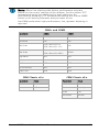
CEM+ and CEM3
Parameter CEM+ CEM3
Curve Mod Square Mod Square
Threshold 1% 1%
Min Scale
120V Retrofit: 6V
230V Retrofit:12V
1%
Max Scale
120V Retrofit: 140V
230V Retrofit:280V
100%
Regulation OFF OFF
Preheat Disabled Disabled
DC Prevent OFF OFF
InrushPrevent OFF OFF
Scale Load 100 100
CEM Classic v2.x
Parameter Value
Mode Normal
Boost 117
CEM Classic v3.x
Parameter Value
Mode Normal
Curve Mod-Square
Scale 140
Threshold Normal

14 Source 4WRD Installation and User Manual
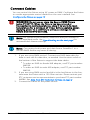
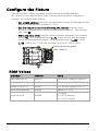
Configure the Fixture
The two-button, seven-segment display shows the DMXaddress,
ACmode, or the manually-set level. Use the up and down navigation
buttons to configure the fixture.
•
Set a DMX address: Use the up and down arrows to navigate to the
desired DMX address number (1–512).
•
Set the fixture to use line-dimming (ACmode): Use the down
arrow to navigate one number below DMX address 1. The display
will read AC.
•
Manually set a level: Use the down arrow to navigate one number
below AC. The display will read L.FL (Level = Full). Usethe down
arrow to decrease the level to a percentage of full (L.99 = 99%,
L.98 = 98%, etc.). You can set levels from 0%–100% (full).
Up and down navigation
User interface
RDMValues
Parameter RDMPID Value
Manufacturer ID 0x6574 Electronic Theatre Controls
Model ID (120V) 0x0800 ETC Source 4WRD (120V)
Model ID(230V) 0x0801 ETC Source 4WRD (230V)
DMX Start Address 0x00F0 Range = 1–512
Personality ID 0x00E0
1 = DMX
2 = ACDimming
3 = Local Control

Source 4WRD Installation and User Manual 15
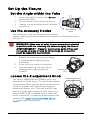
Set Up the Fixture
Set the Angle within the Yoke
Yoke locking
knob
1. Loosen the yoke locking knob. Do not
remove the knob.
2. Tilt the fixture to the desired position.
3. Tighten the yoke locking knob to secure
in position.
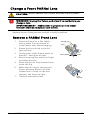
Use the Accessory Holder
The accessory holder is equipped with a spring-
loaded retaining clip that prevents color frames and accessories from
falling out.
WARNING: Make sure all color frame accessories are locked
in position with the retaining clip before hanging the fixture.
AVERTISSEMENT : S’assurer que tous les porte-filtres sont
verrouillés en place à l’aide du verrouillage de la cassette
avant de suspendre le projecteur.
Retaining
clip
1. Release the retaining clip by pushing
it sideways while gently pulling
backwards.
2. Insert the color frame or accessory.
3. Lock the retaining clip by pushing
sideways while gently pushing
forward.
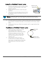
Loosen the Z-adjustmentKnob
Z-adjustment knob
The Source 4WRD PAR and PARNel optics are
optimized for PEAKfocus. Turn the Z-adjustment
knob toward PEAK until the knob becomes loose,
and then tighten the Z-adjustment knob an
additional quarter turn. This sets the LED light
source into the appropriate position within the
Source 4WRD PAR or PARNel fixture. After the
knob is loosened, no additional adjustments are
needed. See
Install the Source 4WRDLED on
page8
for more information.

16 Source 4WRD Installation and User Manual
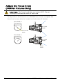
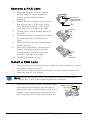
Adjust the Focus Knob
(PARNelFixturesOnly)
CAUTION:
The focus knob does not rotate 360°. Do not
attempt to exceed the limit of the knob.
To adjust focus knob tension on a PARNel lens, loosen or tighten the
focus knob screw, which is located on the bottom of the lens.
Focus knob in
flood position
Focus knob in
spot position
Focus knob
screw
45° field
angle
25° field
angle
Focus
knob
La page est en cours de chargement...
La page est en cours de chargement...
La page est en cours de chargement...
La page est en cours de chargement...
La page est en cours de chargement...
La page est en cours de chargement...
La page est en cours de chargement...
La page est en cours de chargement...
-
 1
1
-
 2
2
-
 3
3
-
 4
4
-
 5
5
-
 6
6
-
 7
7
-
 8
8
-
 9
9
-
 10
10
-
 11
11
-
 12
12
-
 13
13
-
 14
14
-
 15
15
-
 16
16
-
 17
17
-
 18
18
-
 19
19
-
 20
20
-
 21
21
-
 22
22
-
 23
23
-
 24
24
-
 25
25
-
 26
26
-
 27
27
-
 28
28


ETC Source 4WRD Installation and User Manual
- Taper
- Installation and User Manual
dans d''autres langues
- English: ETC Source 4WRD
Documents connexes
Autres documents
-
Vari-Lite VLZ WASH Manuel utilisateur
-
-
-
Chauvet COLORdash Accent Series Manuel utilisateur
-
EuroLite TMH-155 Moving-Head Manuel utilisateur
-
-
-
-
Prescolite LITEISTRY DMX Guide d'installation
-
Kessil A500X Tuna Blue Manuel utilisateur