Gas Clip Technologies Single Gas Clip Portable Gas Detector Manuel utilisateur
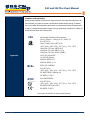
- Catégorie
- Détecteurs de monoxyde de carbone (CO)
- Taper
- Manuel utilisateur

Single Gas Clip Plus
Single Gas Clip
User’s Manual
GASCLIPTECH.COM

SGC and SGC Plus User’s Manual
UM SGC v3.0
Warning Statements/Avertissement .................................................... 1
READ FIRST BEFORE OPERATION ............................................................ 1
Detector Components ................................................................. 3
Display Components ................................................................... 4
Display Layout ............................................................................. 4
Display Details ............................................................................. 4
Basic Operation ....................................................................... 5
Turning the Detector On .................................................................... 5
Turning the Detector O. . . . . . . . . . . . . . . . . . . . . . . . . . . . . . . . . . . . . . . . . . . . . . . . . . . . . . . . . . . . . . . . . . . . 5
Performing a Self-test. . . . . . . . . . . . . . . . . . . . . . . . . . . . . . . . . . . . . . . . . . . . . . . . . . . . . . . . . . . . . . . . . . . . . . . 5
Alarms .................................................................................
Detector Maintenance ................................................................. 8
Bump Test Interval (bUP). . . . . . . . . . . . . . . . . . . . . . . . . . . . . . . . . . . . . . . . . . . . . . . . . . . . . . . . . . . . . . . . . . . . 8
O2 Detector-Calibration ..................................................................... 8
Cleaning ................................................................................... 9
Hibernation (SGC Plus Only) ................................................................ 9
Detector Records (Logs) ...............................................................10
Event Log ..................................................................................10
How to Retrieve Data Logs Using the GCT IR Link . . . . . . . . . . . . . . . . . . . . . . . . . . . . . . . . . . . . . . . . . . . . 10
Accessories and Replacement Parts . . . . . . . . . . . . . . . . . . . . . . . . . . . . . . . . . . . . . . . . . . . . . . . . . . . 11
Detector Specications ...............................................................12
Warranty .............................................................................14
Contact Information . . . . . . . . . . . . . . . . . . . . . . . . . . . . . . . . . . . . . . . . . . . . . . . . . . . . . . . . . . . . . . . . . . 15
CONTENTS

SGC and SGC Plus User’s Manual
UM SGC v3.0 1 of 15
WARNING STATEMENTS
If the detector is past the “Activate Before Date” on the package, please do not activate.
Do not attempt part replacement or substitution as this could impair the intrinsic safety rating and will void the
warranty of the product.
Before daily use check the following:
1) Sensor and alarm ports are clear of any obstructions i.e. debris or blockage
2) Perform the Self-test to ensure proper operation of visual, audible, and vibrating alarms
3) Conrm receipt of a check mark in the upper left hand corner signaling a successful Self-test
4) Inspect the detector for any physical signs of damage
DO NOT use IR communications when an explosive atmosphere may be present.
The battery may present a re or chemical burn hazard if mistreated. Do not disassemble, heat above 100°C (212°F)
or incinerate. Contact Gas Clip Technologies for replacement instructions. Use of another battery may present a
risk of re or explosion.
Keep new and used batteries away from children.
DO NOT expose the detector to sensor poisons such as, but not limited to: alcohol, citrus-based cleaners, silicones,
lead compounds (e.g. tetraethyl lead), sulfur compounds, phosphorus, halogenated hydrocarbons and aerosols.
Exposure to poisons may impair the accuracy and/or response time of the detector.
If suspected sensor poisoning has occurred, recheck the detector (both calibrate and bump test).
Calibrate the SGC O detector at least every 30 days. Make sure to calibrate in a clean air environment. See SGC O
detector section for instructions on calibration.
The CO and H2S versions of both the Single Gas Clip and SGC Plus do not require calibration for the life of the
product.
The detector should be bump tested before each day’s use with a known concentration of gas to conrm its ability
to respond to gas. The recommended target gas concentrations for the dierent detector versions are as follows--
HS: 25 ppm, CO: 200 ppm, O: 18%. Calibrate the detector if the readings are not within the specied limits.
Bump tests can be performed either manually or through the SGC Dock. If a manual test is to be performed, make
sure to test in a clean air environment.
Any rapid up-scale reading followed by a declining or erratic reading may indicate a gas concentration beyond
upper scale limit which may be hazardous.
Strong Electromagnetic Interference (EMI) may cause incorrect operations.
If a detector fails the self-test or bump test, please discontinue use.
The detector contains a lithium battery that must be disposed of by a qualied recycler. Check local regulations for
proper disposal.
Do not substitute internal components as this may interfere with the intrinsic safety of the device.
Do not attempt to replace the battery or sensor. This product is designed to be disposable. Changing these
components will void the warranty.
If you suspect any malfunction or have any technical problems please contact GCT at 877-525-0808.
READ FIRST BEFORE OPERATION
Gas Clip Technologies (GCT) Single Gas Clip and SGC Plus detectors are personal safety devices designed to detect the
presence of specic toxic gases such as Carbon Monoxide (CO), Hydrogen Sulde (
H2S
) or Oxygen (
O
) deciency. Before
operation, please ensure you have been properly trained on the use of the equipment and appropriate actions to take in
the event of an alarm condition.

SGC and SGC Plus User’s Manual
UM SGC v3.0 2 of 15
AVERTISSEMENTS
Si le détecteur a dépassé la date « Activer avant » sur l’emballage, veuillez ne pas l’activer.
N’essayez pas de remplacer ou de substituer des pièces car cela pourrait nuire à la cote de sécurité intrinsèque et
annulera la garantie du produit.
Avant l’utilisation quotidienne, vériez les points suivants:
1) Les ports du capteur et de l’alarme sont dégagés de toute obstruction, c’est-à-dire des débris ou un
blocage
2) Eectuez l’autotest pour garantir le bon fonctionnement des alarmes visuelles, sonores et vibrantes
3) Conrmez la réception d’une coche dans le coin supérieur gauche signalant un autotest réussi
4) Inspectez le détecteur pour tout signe physique de dommage
NE PAS utiliser les communications IR lorsqu’une atmosphère explosive peut être présente.
La batterie peut présenter un risque d’incendie ou de brûlure chimique si elle est maltraitée. Ne pas démonter,
chauer à plus de 100°C (212°F), ou incinérer. Contactez Gas Clip Technologies pour obtenir des instructions de
remplacement. L’utilisation d’une autre batterie peut présenter un risque d’incendie ou d’explosion.
Conservez les piles neuves et usagées hors de portée des enfants.
NE PAS exposer le détecteur à des poisons de capteur tels que, mais sans s’y limiter: des nettoyants à base d’alcool
et d’agrumes, des silicones, des composés de plomb (par exemple, plomb tétraéthyle), composés soufrés,
phosphore, hydrocarbures halogénés et aérosols. L’exposition à des poisons peut altérer la précision et/ou le
temps de réponse du détecteur.
Si un empoisonnement du capteur est suspecté, revérier le détecteur (à la fois étalonné et test fonctionnel).
Étalonnez le détecteur SGC O au moins tous les 30 jours. Assurez-vous de calibrer dans un environnement d’air
propre. Voir la section sur le détecteur SGC O pour des instructions sur l’étalonnage.
Les versions CO et HS du Single Gas Clip et du SGC Plus ne nécessitent pas d’étalonnage pendant toute la durée
de vie du produit.
Le détecteur doit être testé avant chaque utilisation quotidienne avec une concentration de gaz connue pour
conrmer sa capacité à réagir au gaz. Les concentrations de gaz cible recommandées pour les diérentes versions
de détecteurs sont les suivantes : H2S : 25 ppm, CO : 200 ppm, O : 18 %. Étalonnez le détecteur si les lectures ne
sont pas dans les limites spéciées.
Les tests fonctionnels peuvent être eectués manuellement ou via le SGC Dock. Si un test manuel doit être
eectué, assurez-vous de tester dans un environnement d’air propre.
Toute rapide haut de gamme lecture suivi d’une lecture décroissante ou erratique peut indiquer une
concentration de gaz au-delà de la limite supérieure de l’échelle ce qui peut être dangereux.
De fortes interférences électromagnétiques (EMI) peuvent entraîner des opérations incorrectes.
Si un détecteur échoue à l’auto-test ou au test fonctionnel, veuillez cesser de l’utiliser.
Le détecteur contient une pile au lithium qui doit être mise au rebut par un recycleur qualié. Vériez les
réglementations locales pour une élimination appropriée.
Ne remplacez pas les composants internes car cela pourrait interférer avec la sécurité intrinsèque de l’appareil.
N’essayez pas de remplacer la pile ou le capteur. Ce produit est conçu pour être jetable. Le changement de ces
composants annulera la garantie.
Si vous soupçonnez un dysfonctionnement ou rencontrez des problèmes techniques, veuillez contacter GCT au
877-525-0808.
À LIRE AVANT L’UTILISATION
Les détecteurs Gas Clip Technologies (GCT) Single Gas Clip et SGC Plus sont des dispositifs de sécurité personnels conçus
pour détecter la présence de gaz toxiques spéciques tels que le monoxyde de carbone (CO), le sulfure d’hydrogène
(
H2S
) ou le manque d’oxygène (
O
). Avant l’utilisation, veuillez vous assurer que vous avez été correctement formé à
l’utilisation de l’équipement et aux mesures appropriées à prendre en cas de condition d’alarme.

SGC and SGC Plus User’s Manual
UM SGC v3.0 3 of 15
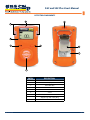
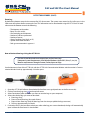
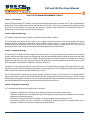
DETECTOR COMPONENTS
ENTRY DESCRIPTION
1 Audible Alarm Port
2 Display
3 Alarm Bar LEDs
4 Maintenance LEDs
5 Power Button
6 Sensor
7 Infrared (IR) Communication Window
8Alligator Clip with Safety Ring
9Certication Label
1
2
3
4
5
6
7
8
9

SGC and SGC Plus User’s Manual
UM SGC v3.0 4 of 15
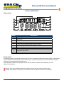
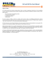
ENTRY DESCRIPTION
1 Alarm Condition
2 Self-Test Icon
3 Test Reminder Icon
4Gas Type Identiers
5 Battery Indicator (Used During Real-Time Gas reading)
6 Life Remaining or Real Time Gas Reading Data
7 High And Low Alarm Set Point Icon
8/11 Detector Life Remaining Icon
9 Infrared Data Transfer Icon
10 Last Maximum Exposure
DISPLAY COMPONENTS
Display Layout
Display Details
The detector utilizes a special high viewing angle LCD that is designed to enhance the screen visibility. In the absence
of gas, it displays life remaining. In those cases where gas is present, the display will automatically shift to a display
that shows gas concentration and a battery icon.
*Note the display mode can be changed in the GCT IR Link software with the “Sensor Reading” and “Life
Remaining”user options.
Warning: Users must familiarize themselves with the icons in both non-alarm and alarm states.
Warning: If the display is missing icons or cannot be clearly read, please contact GCT immediately.

SGC and SGC Plus User’s Manual
UM SGC v3.0 5 of 15
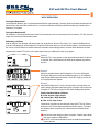
Screen 1:
When the “Test” Icon appears in the upper left hand corner, a self-test
is required. Press the button on the front of the detector to perform
the test.
BASIC OPERATION
Turning the Detector On
To activate the detector, press and hold down button for approximately 5 seconds. Upon activation, the detector will
vibrate, ash, and sound the audible alarm. A successful activation will display the life remaining in months on the
detector as 24 months.
Turning the Detector O
This detector is not designed to be turned o. Once activated, it will run continuously for 24 months. SGC Plus may last
longer if it’s been put in hibernation mode.
Performing a Self-test
Prior to daily use, the detector will prompt the user to perform a self-test. This process is a simple and eective way
to ensure safe operation of the detector. During the self-test the audio, visual, and vibrating alarms are activated and
the sensor is tested. Below we outlined the most common screen congurations, however if the detector has been
programmed via the GCT IR Link, or has been exposed to gas, additional screens may appear:
Screen 2:
After pressing the button, the full element LCD screen will appear.
During the self-test ensure that the following occur: (1) the detector
emits one audible beep and vibrates, (2) all LED’s light up and (3) all
LCD display elements appear.
Screen 3:
After the full element LCD screen, the low alarm and high alarm set
points will be displayed. Note: these alarm set points can be adjusted
using the GCT IR Link or Single Gas Clip Dock conguration options.
Factory Standard Alarm Set Points:
H2S: Low 10 ppm / High 15 ppm
CO: Low 35 ppm / High 200 ppm
O: Min 19.5% / Max 23.5%
*Note these set points can be changed using the GCT IR Link. Please
refer to the SGC IR Link documentation for further details. To display
the detector alarm set points press the button on the front of the
detector.
Use caution when changing alarm set points. Conrm these levels
with your company safety ocer.
DO NOT use IR communications when an explosive atmosphere
may be present.

SGC and SGC Plus User’s Manual
UM SGC v3.0 6 of 15
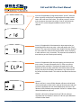
Screen 7:
When a self-test is successful the detector will turn to the original
screen and display a check mark in place of where the test icon was
previously displayed and one short audible beep will sound. The
detector will by default prompt another “Self-test” in 20 hours from
when the button was pressed.
Note this value can be changed via the GCT IR Link software
anywhere from 8 to 20 hours. See the GCT IR Link Quick Reference
Guide for further detail.
Screen 6: (if applicable): After the peak reading and time passed
since screens, a screen will appear with CLP. If the user presses
the button down while this is displayed, the peak value on the
detector will be reset. Note: while the value will be cleared on the
display, the value will be held in the detector’s log. See the event
log section for further details. This value can be cleared on the next
screen.
Screen 5: (if applicable): If the detector has been exposed to gas
exceeding the low alarm set point, a value will appear with “max”
next to it. This represents the peak value (highest) that the detector
has seen. After this screen, there will be another screen displaying
a value with hours, days, or months. This represents the amount of
time that has passed since the peak reading.
Screen 4: (If applicable): If programmed with a “User ID”, after the
alarm set points are displayed, a combination of numbers and or
letters will scroll across the screen. This will be a max of 2 screens
with a maximum character limit on the “User ID” of 6 characters.
The “User ID” can be changed/modied via the GCT IR Link
software.

SGC and SGC Plus User’s Manual
UM SGC v3.0 7 of 15
If the self-test fails, the detector emits ve short beeps and ashes before displaying “Test”. Repeat the self-test.
If the self-test fails three (3) consecutive times the detector will enter a Fail Safe mode. Please contact GCT for a
replacement detector.
During normal operation, the battery is continuously monitored. If the battery is low for more than (3) hours the
detector enters Fail Safe mode.
If the battery self-test fails (5) consecutive times the LCD will display “EO5”. In case of an EO5 screen discontinue
use and contact GCT for a replacement detector.
Along with the battery, the sensor is continuously monitored during normal operation. If a problem with the
sensor is detected, the screen will display “EO6”. In case of an EO6 screen, please discontinue use and contact GCT
for a replacement detector.
If the detector is displaying “bUP”, the detector is either due for a bump test because of a scheduled test or has
failed a bump test. Please refer to “Bump Test Interval” for more detail.
If the detector is displaying “EOL” it has reached the end of its operating life. Please discontinue use.
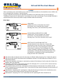
Alarm Types:
LOW ALARM
Audible alarm: One (1) slow beep every second
Visual alarm: One (1) slow ash every second
Vibrating alarm: One (1) slow vibration every second
HIGH ALARM and OVER LIMIT (OL) ALARM
Audible alarm: Two (2) fast beeps every second
Visual alarm: Two (2) fast ashes every second
Vibrating alarm: Two (2) fast vibrations every second
DETECTOR LIFE COUNTDOWN ALERT “EOL”
Once the detector has less than one (1) month of life
remaining the screen will switch to days remaining. When
there is less than one (1) day remaining the screen will
switch to hours remaining. Once the detector has eight
(8) hours remaining it will begin to beep, ash, and vibrate
intermittently. To end the alert push the button down. Once
the detector has reached the end of its operating life the
display will show “EOL” (End of Life).
ALARMS
When a particular gas has a Gas Reading (4) at, or above, its alarm thresholds, the Gas Identier (5) icon will ash and
the associated Alarm Condition (1) icon will display.
During a calibration or bump test, the Calibration/Test Mode (2) icon will display when it is time to apply gas.
The Battery Charge Level (3) is displayed in a 3 bar battery icon as well as a percentage. The percentage calculation is
approximate and can be used to provide a rough estimation of the time remaining.

SGC and SGC Plus User’s Manual
UM SGC v3.0 8 of 15
DETECTOR MAINTENANCE
Bump Test Interval (bUP)
Using the GCT IR Link or GCT Manager, detectors can be programmed to alert the user if a bump test is due. This
interval can be set anywhere from 1 to 365 days. *Note the unit default is to have no bump interval programmed.
If a detector is due for a bump test, the Display will alternate between the months remaining and “bUP”. In addition,
the detector will emit alternating ashes (left and right) every 5 seconds. And the “test” icon will remain even after a
button push.
This alert can be cleared by either placing the detector in a Clip Dock or, if the bump interval is set, by manually
applying gas to the detector. To manually clear the alert, press the Power Button down once and wait for the GAS to
show on the display while the TEST icon ashes. The detector will wait for 45 seconds for the target gas to be applied,
or a button press to skip the bump test. If the SGC is bumped while showing GAS, then it will record as a bump test
in the event log instead of as an exposure. If no gas is applied, it will return to the normal screen and will not record
anything in the event log.
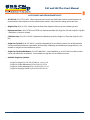
O Detector Calibration
GCT recommends users of the O Single Gas Clip to bump test the detector before using each day.
Single Gas Clip Oxygen (O) detector factory default will prompt the user to calibrate the detector every 30 days. The
user will be prompted by the screen ashing CAL, please see calibration instruction below:
Calibration Instructions
Only perform O calibration in normal air (20.9% Oxygen) that
is free of hazardous gases.
1. Press and hold down the yellow button for four (4) seconds.
2. The screen will display CAL and the O2 icon will ash in the
lower left hand side.
3. After a successful calibration, the detector will emit one (1)
beep, vibration and LED ash.
4. After an unsuccessful calibration, the detector will beep,
ash, and continue to display calibration. If after a few failed
calibrations please contact GCT customer support at 877-525-
0808.

SGC and SGC Plus User’s Manual
UM SGC v3.0 9 of 15
Cleaning
The detector can be cleaned with a soft damp cloth. Do not use solvents, soaps or polishes. A neutral cleaner, like Mat &
Table Top Cleaner (by ACL Staticide) may also be used.
The sensor screen may be cleaned with a soft brush under clean, warm water. Return the lter to the detector once it
has fully dried.
Hibernation (SGC Plus Only)
When the SGC Plus is not used for extended period of time it can be hibernated to suspend the 24 month operation life
countdown.
SGC Plus Hibernation with the GCT IR Link
1. Check that you have installed the GCT IR Link Software and the GCT IR Link USB connections are
plugged in.
2. Click Read Device on the GCT IR Link Software.
3. Note when the detector is hibernated the event log will be cleared. It is highly recommended to save
the event log by pressing the save event log before hibernating.
4. Click on the Hibernate Button, acknowledge the event log message.
5. Keep in front of the GCT IR Link until the “Hibernate OK” message is displayed at the bottom of the GCT
IR Link Software.
6. Conrm the detector screen is blank.
7. If you encounter any problems please contact GCT customer support at 877-525-0808.
SGC Plus Hibernation with the Clip Dock
1. Check that the Clip Dock is turned on and USB memory is inserted.
2. The Clip Dock is capable of hibernating 4 detectors at one time: place the desired amount of detectors
in the docking station.
3. Press and hold the bump test and calibration buttons down simultaneously for approximately 2
seconds.
4. A successful hibernation will result in a GREEN light on for the corresponding detector number.
5. Note the event log will be automatically stored on the Clip Dock USB memory.
6. Conrm the detector screen is blank.
7. If you encounter any problems please contact GCT customer support at 877-525-0808.

SGC and SGC Plus User’s Manual
UM SGC v3.0 10 of 15
How to Retrieve Data Logs Using the GCT IR Link
*You must have Microsoft Excel to open Data and/or Event Logs
*Computer System Requirements: Available for Windows© based PCs (Vista, 7, 8.x, 10)
*Browser requirements: Google Chrome, Firefox, Opera or Edge
Set the detector in front of the GCT IR Link with the GCT IR Link Communication Window and the monitor’s Commu-
nication Window lined up approximately 2-3 inches apart.
1. Open the GCT IR Link Software (downloaded for free from www.gascliptech.com under Resources tab).
2. Click on Download Logs icon at the top left corner.
3. Select Destination Folder (wherever you want to store the logs on your computer).
4. Select what kind of logs you want to download:
a. Event Logs Only
b. Events & Partial Data Log (last week of data)
c. Events & New Data Logs Only (All data logs from last time you pulled the logs to current)
d. Full Logs (approximately 2 months)
5. If a check mark is in the box above where you select what logs you want to download, the logs will automatically
open in Microsoft Excel once it’s downloaded.
DETECTOR RECORDS LOGS
Event Log
By default the detector stores the last twenty-ve (25) alarm events. The system stores events by rst in rst out, i.e. the
26th event will replace the rst event and so on. This information can be downloaded using the GCT IR Link. For each
alarm event the detector records the following:
• The detector serial number
• Bump Test (Yes or No)
• Life remaining on the detector
• Number of self-tests performed
• Number of events
• Alarm Condition (Low, High, or OL)
• Specic event date and time
• Peak gas concentration in ppm or %

SGC and SGC Plus User’s Manual
UM SGC v3.0 11 of 15
ACCESSORIES AND REPLACEMENT PARTS
• GCT IR Link: (P/N: GCT-IR-LINK) - Infrared communications device and USB cable used for communications be-
tween detector and computer to easily make rmware updates, adjust detector settings and record data.
• Alligator Clip: (P/N: AL-CLIP) - Metal clip on the back of the detectors that can clip on to clothing or belts.
• Replacement Filters: (P/N: FILTER-10 or FILTER-50) - Replacement lters for Single Gas Clip and Single Gas Clip Plus
- available in a 10 pack or 50 pack.
• Calibration Cap: (P/N: SGC-CALCAP) - Replacement calibration cap for the Single Gas Clip or the Single Gas Clip
Plus.
• Single Gas Clip Dock: (P/N: SGC-DOCK) - portable, chargeable all-in-one docking station in a durable portable
case for automated 4-detector simultaneous bump testing, calibrating, record keeping and programming - also
available in a High Pressure and Ethernet version.
• Single Gas Clip Dock Wall Mount: (P/N: SGC-WMDOCK) - Same capabilities as an SGC Dock in a metal case that
can be wall mounted or stand alone. - also available in a High Pressure and Ethernet version.
• Available Single Gas Cylinders:
• Single Gas Oxygen (O) 58L P/N: SGC-02-58 - 18% O 58L
• Single Gas Carbon Monoxide (CO) 58L P/N: SGC-CO-58
• Single Gas Carbon Monoxide (CO) 116L P/N: SGC-CO-116
• Single Gas Hydrogen Sulde (H2S) 58L P/N: SGC-H2S-58

SGC and SGC Plus User’s Manual
UM SGC v3.0 12 of 15
Size 3.3 x 2 x1.1 in (85x50x28 mm)
Weight 2.7 oz (76 g)
Temperature -40 to 1220F (-40 to +500C) for CO and H2S, -31 to +1220F (-35 to +500C) for O
Humidity 5% to 95% non-condensing relative humidity
Ingress Protection IP 67
Alarms Visual, vibrating, audible (minimum 95dB)
LEDs 4 red alarm bar LEDs
Display Liquid Crystal Display (LCD)
Battery Life 24 months of operation/2 minutes of alarm every day
Event Log Storage Last 25 events. Newer events replace older events
Warranty Full 2 years (SGC) or 3 years (SGC Plus)
Gas Range Resolution Accuracy* T90*
Gases
H2S 0 - 100 ppm 0.1 < 2 ppm < 30 s
CO 0 - 300 ppm 1 < 5 ppm < 30 s
O 0 - 30% vol. 0.1 < 0.7% vol. < 15 s
Sensor Type Single plug-in electrochemical cell
User Options User ID, Low Alarm, High Alarm, Calibration Interval, Bump Interval, Self-Test Interval,
Calibration Gas, Display sensor/life remaining, Bump Due LED
DETECTOR SPECIFICATIONS
*Sensor performance is dependent on many factors, including temperature, humidity, sensor age, lter cleanliness,
gas delivery, and calibration accuracy. Typical performance will be better than the given limits under most circum-
stances.

SGC and SGC Plus User’s Manual
UM SGC v3.0 13 of 15
Approvals
Conditions of Acceptability:
Under certain extreme circumstances, exposed plastic and unearthed metal parts of
the enclosure may store an ignition-capable level of electrostatic charge. Therefore,
the user/installer shall implement precautions to prevent the buildup of electrostatic
charge, e.g. locate the equipment where a charge-generating mechanism is unliely to
be present and clean with a damp cloth
Intrinsically Safe/Sécurité lntrinsèque
Class I, Division 1, Groups A, B, C, and D T4
Ex ia IIC T4 Ga
Class I, Zone 0, AEx ia IIC T4 Ga
-40°C (H2S) / -40°C (CO) / -35°C (O₂) ≤ Ta ≤ +50°C
CAN/CSA-C22.2 No. 60079-0:15
CAN/CSA-C22.2 No. 60079-11:14
CAN/CSA-C22.2 No. 0-M91 (R2001)
C22.2 No 142-M1987
UL 916 Fifth Edition
ANSI/UL 60079-0:13
ANSI/UL 60079-11:13
Sira 16ATEX2087X
Ex ia IIC T4 Ga
-40°C (H2S) / -40°C (CO) / -35°C (O₂) ≤ Ta ≤ +50°C
EN 60079-0:2012/A11:2013
EN 60079-11:2012
IECEx CSA 16.0020X
Ex ia IIC T4 Ga
-40°C (H2S) / -40°C (CO) / -35°C (O₂) ≤ Ta ≤ +50°C
IEC 60079-0:2011 Edition: 6.0
IEC 60079-11:2011
II 1G Ex ia
2813
CSA
IECEx
ATEX
Please note: the SCG Plus CO has been discontinued.

SGC and SGC Plus User’s Manual
UM SGC v3.0 14 of 15
GAS CLIP TECHNOLOGIES WARRANTY POLICY
Section 1. Introduction
All Gas Clip Technologies (GCT) products have been tested to the highest quality standards by GCT. This Limited Warranty
oered by GCT covers defects in material or workmanship in GCT products. This warranty extends to the original purchaser
only and is non-transferable. Only consumers purchasing GCT products from authorized GCT distributors or from GCT
directly may obtain coverage under our limited warranties.
Section 2. Extent of Coverage
GCT warrants all products against defects in material or workmanship as follows:
GCT will replace at no charge for parts only or, at its option, replace any product or part of the product that proves
defective because of improper workmanship and/or material, under normal use, service and maintenance. If GCT is
unable to provide a replacement and repair is not practical or cannot be made in a timely fashion, GCT may, but is not
obligated to, elect to refund the purchase price in exchange for the return of the product.
Section 3. Length of Coverage
The standard GCT Product Warranty length of coverage shall be two (2) years, beginning upon the date of activation
of the product by the original end user or beginning upon the “Activate Before Date” printed on the product box label,
whichever occurs rst. The standard GCT Product Warranty length of coverage for products sold without an “Activate
Before Date” shall be two (2) years, beginning upon the original end user’s documented date of purchase or one (1) year
from the product’s original Date of Shipment, whichever occurs rst.
The Multi Gas Clip Simple PLUS (MGC-S-PLUS) shall have a GCT Product Warranty length of coverage of three (3) years,
beginning upon the date of activation of the product by the original end user or beginning upon the “Activate Before
Date” printed on the product box label, whichever occurs rst.
The GCT Product Warranty length of coverage for Single Gas Clip Plus monitors (SGC-P-H and SGC-P-C) shall be three (3)
years of elapsed time, or two (2) years of operational use by the original end user, whichever occurs rst. The GCT Product
Warranty period for Single Gas Clip Plus monitors shall begin upon the date of activation by the original end user or upon
the “Activate Before Date” printed on the product box label, whichever occurs rst.
Section 4. Exceptions to Coverage
GCT’s warranties do not cover any problem that is caused by:
• Conditions, malfunctions or damage not resulting from defects in material or workmanship.
• Conditions, malfunctions or damage resulting from normal wear and tear, improper maintenance, misuse, abuse,
negligence, accident or alteration.
• Accessories, connected materials and products, or related products not manufactured by GCT.
• Our limited warranties are void if a product is returned with removed, damaged or tampered labels or any
alterations (including removal of any component or external cover).

SGC and SGC Plus User’s Manual
UM SGC v3.0 15 of 15
Gas Clip Technologies, Inc.
305 W. FM 1382, Ste. 540, Cedar Hill, TX 75104
Phone: +1 (972) 775-7577 • Toll Free: 1 (877) 525-0808 • Fax: +1 (972) 775-2483
[email protected]om • www.gascliptech.com
Section 5. Claims
GCT will not provide any warranty coverage unless claims are made in compliance with all terms of the controlling
warranty statement included with your product and proper return procedures are followed. To request warranty service,
please provide:
• The serial number of the defective product
• A description of the problem
• A valid shipping address
• Full Data Logs
To start the process of ling a claim for a product under warranty, please e-mail [email protected]om with the
aforementioned information. Please note that the defective product must be returned to GCT address which is 305 W. FM
1382, Suite 540, Cedar Hill, TX 75104, with provided prepaid shipping label.
GCT will retain possession of disposable detectors that are returned and found to be beyond their warranty period. This
includes, but is not limited to, detectors that display EOL (End Of Life) on the screen.
REPAIR OR REPLACEMENT (OR, IN LIMITED CIRCUMSTANCES, REFUND OF THE PURCHASE PRICE) AS PROVIDED UNDER
THIS WARRANTY IS THE EXCLUSIVE REMEDY OF THE PURCHASER. GCT NEITHER ASSUMES NOR AUTHORIZES ANY PERSON
TO CREATE FOR IT ANY OTHER OBLIGATION OR LIABILITY IN CONNECTION WITH THIS PRODUCT.
GCT SHALL NOT BE LIABLE TO PURCHASER OR ANY OTHER PERSON FOR ANY INCIDENTAL, SPECIAL OR CONSEQUENTIAL
DAMAGES, ARISING OUT OF BREACH OF THIS WARRANTY OR ANY IMPLIED WARRANTY (INCLUDING BUT NOT LIMITED TO
ANY IMPLIED WARRANTY OF MERCHANTABILITY).
-
 1
1
-
 2
2
-
 3
3
-
 4
4
-
 5
5
-
 6
6
-
 7
7
-
 8
8
-
 9
9
-
 10
10
-
 11
11
-
 12
12
-
 13
13
-
 14
14
-
 15
15
-
 16
16
-
 17
17


Gas Clip Technologies Single Gas Clip Portable Gas Detector Manuel utilisateur
- Catégorie
- Détecteurs de monoxyde de carbone (CO)
- Taper
- Manuel utilisateur
dans d''autres langues
Documents connexes

Autres documents
-
ESAB M3® Plasma G2 (ICH) Plasma System Manuel utilisateur
-
-
-
-
BW Technologies MicroClip XT Quick Reference Manual
-
Altair Single-Gas Detector Mode d'emploi
-
Danfoss EKC 326 Guide d'installation
-
DSC iotega WS900x Manuel utilisateur
-
Sharper Image Multi-Function Electric Steam Cleaner Le manuel du propriétaire
-