
EN
DE
FR
ES
Additional information
Zusatzinformation
Informations supplémentaires
Información adicional
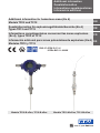
Additional information for hazardous areas (Ex d)
Models TR12 and TC12
Zusatzinformation für explosionsgefährdete Bereiche (Ex d)
Typen TR12 und TC12
Informations complémentaires concernant les zones explosives
(Ex d), types TR12 et TC12
Información adicional para zonas potencialmente explosivas (Ex d)
Modelos TR12 y TC12
Models TR12-B-xDxx, TC12-B-xDxx Models TR12-M-xDxx, TC12-M-xDxx
BVS 07 ATEX E 071 X
IECEx BVS 11.0042X

EN
DE
FR
ES
2
14280101.01 03/2019 EN/DE/FR/ES
WIKA additional information TR12/TC12, flameproof enclosure (Ex d)
Operating instructions models TR12, TC12 (Ex d)
Page
3 - 20
Betriebsanleitung Typen TR12, TC12 (Ex d)
Seite
21 - 38
Mode d'emploi types TR12, TC12 (Ex d)
Page
39 - 56
Manual de instrucciones modelos TR12, TC12 (Ex d)
Página
57 - 74
© 03/2019 WIKA Alexander Wiegand SE & Co. KG
All rights reserved. / Alle Rechte vorbehalten.
WIKA
®
is a registered trademark in various countries.
WIKA
®
ist eine geschützte Marke in verschiedenen Ländern.
Prior to starting any work, read the operating instructions!
Keep for later use!
Vor Beginn aller Arbeiten Betriebsanleitung lesen!
Zum späteren Gebrauch aufbewahren!
Lire le mode d‘emploi avant de commencer toute opération !
A conserver pour une utilisation ultérieure !
¡Leer el manual de instrucciones antes de comenzar cualquier trabajo!
¡Guardar el manual para una eventual consulta!

Declarations of conformity can be found online at www.wika.com.
EN
14280101.01 03/2019 EN/DE/FR/ES
WIKA additional information TR12/TC12, flameproof enclosure (Ex d) 3
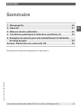
Contents
Contents
1. Ex marking 4
2. Safety 5
3. Commissioning, operation 7
4. Special conditions for use (X conditions) 17
5. Calculation examples for self-heating at the thermowell tip 18
Appendix: EU declaration of conformity 20

EN
14280101.01 03/2019 EN/DE/FR/ES
WIKA additional information TR12/TC12, flameproof enclosure (Ex d)4
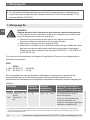
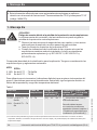
1. Ex marking
DANGER!
Danger to life due to loss of explosion protection
Non-observance of these instructions and their contents may result in the
loss of explosion protection.
▶
Observe the safety instructions in this chapter and further explosion
instructions in these operating instructions.
▶
Follow the requirements of the ATEX directive.
▶
Observe the information given in the applicable type examination
certificate and the relevant regulations for installation and use in
hazardous areas (e.g. IEC 60079-11, IEC 60079-10 and IEC 60079-14).
Check whether the classification is suitable for the application. Observe the relevant
national regulations.
ATEX
IECEx
II 1/2G Ex db IIC T1 ... T6 Ga/Gb
II 2G Ex db IIC T1 ... T6 Gb
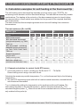
For applications without transmitters (digital displays) requiring instruments of equipment
group II (potentially explosive gas atmospheres), the following temperature class
classification and ambient temperature ranges apply:
Table 1
Marking Temperature
class
Ambient
temperature
range (T
a
)
Max. surface
temperature
(T
max
) at the probe or ther-
mowell tip
ATEX IECEx
II 1/2G Ex db IIC T1 ... T6
Ga/Gb
II 2G Ex db IIC T1 ... T6
Gb
T1 ... T6 (-50)
1)
-40 ... +80 °C T
M
(medium temperature) +
self-heating
For this, the special conditions
must be observed (see
chapter 4 “Special conditions
for use (X conditions)”).
1) The values in brackets apply to special designs. These probes are manufactured using special sealing compounds.
Moreover, they feature cases made of stainless steel and cable glands for low-temperature ranges.
1. Ex marking
Supplementary documentation:
▶
This additional information for hazardous areas applies in conjunction with the
operating instructions “Resistance thermometer TR12 and thermocouple TC12”
(article number 14064370).

EN
14280101.01 03/2019 EN/DE/FR/ES
WIKA additional information TR12/TC12, flameproof enclosure (Ex d) 5
When there is a built-in transmitter and/or a digital display, the special conditions from the
type examination certificate (see chapter 4 “Special conditions for use (X conditions)”)
apply.
2. Safety
2.1 Explanation of symbols
DANGER!
... indicates a potentially dangerous situation in the hazardous area that can
result in serious injury or death, if not avoided.
2.2 Intended use
The thermometers described here are suitable for temperature measurement in hazardous
areas.
The non-observance of the instructions for use in hazardous areas can lead to the loss
of the explosion protection. Adhere to the following limit values and instructions (see data
sheet).
There are 3 different variants available:
■
Variant 1: The thermometer is fitted to a certified enclosure with “flameproof enclosure”
ignition protection type, which has a terminal block built into it.
■
Variant 2: The thermometer is fitted to a certified enclosure with “flameproof enclosure”
ignition protection type, which has an electronic assembly built into it.
■
Variant 3: The thermometer is fitted to certified equipment (transmitter) with an ignition
protection type of “flameproof enclosure”.
The thermometer models TR12-B or TC12-B in variants 1 and 2 are fitted to Ex d certified
connection heads or connection housings from WIKA's 1/4000, 5/6000 or 7/8000 series.
These cases and covers are made from stainless steel or aluminium. The cover is
optionally available with a glass window.
Alternatively, the thermometers can be built into other certified cases (see approval
BVS 07 ATEX E 071 X, IECEx BVS 11.0042X “WIKA case and instrument listings”).
Possible sensor measuring ranges:
Model TR12: -196 ... +600 °C
Model TC12: -40 ... +1,200 °C
1. Ex marking / 2. Safety

EN
14280101.01 03/2019 EN/DE/FR/ES
WIKA additional information TR12/TC12, flameproof enclosure (Ex d)6
2.3 Responsibility of the operator
The responsibility for classification of zones lies with the plant operator and not the
manufacturer/supplier of the equipment.
2.4 Personnel qualification
The skilled electrical personnel must have knowledge of ignition protection types,
regulations and provisions for equipment in hazardous areas.
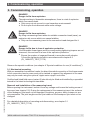
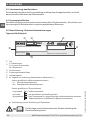
2.5 Labelling, safety marks
Product label (example)
2. Safety
TR12-M-IIBZ
1 x Pt100 / A / 3 (F) -50 ... +500 °C
Um = DC 30 V / Pm = 2 W
BVS 07 ATEX E 071 X
IECEx BVS 11.0042X
II 2 G Ex db IIC T* Gb
EN 60751
0158
WIKA Alexander Wiegand SE & Co.KG, D-63911 Klingenberg
Made in Germany 2013
WARNING: DO NOT OPEN WHILE ENERGIZED!
11012345
TC12-M-IDBZ
1 x Typ K / 1 / . 0 ... +600 °C
Um = DC 30 V / Pm = 2 W
BVS 07 ATEX E 071 X
IECEx BVS 11.0042X
II 2 G Ex db IIC T* Gb
EN 60584-1
0158
WIKA Alexander Wiegand SE & Co.KG, D-63911 Klingenberg
Made in Germany 2013
WARNING: DO NOT OPEN WHILE ENERGIZED!
11012345
TR12-B-IDBZ
1 x Pt100 / A / 3 (F) -50 ... +500 °C
Um = DC 30 V / Pm = 2 W
BVS 07 ATEX E 071 X
IECEx BVS 11.0042X
II 2 G Ex db IIC T* Gb
EN 60751
0158
WIKA Alexander Wiegand SE & Co.KG, D-63911 Klingenberg
Made in Germany 2013
WARNING: DO NOT OPEN WHILE ENERGIZED!
11012345
TC12-B-IDBZ
1 x Typ K / 1 / . 0 ... +600 °C
Um = DC 30 V / Pm = 2 W
BVS 07 ATEX E 071 X
IECEx BVS 11.0042X
II 2 G Ex db IIC T* Gb
EN 60584-1
0158
WIKA Alexander Wiegand SE & Co.KG, D-63911 Klingenberg
Made in Germany 2013
WARNING: DO NOT OPEN WHILE ENERGIZED!
11012345
Model
A = measuring insert
B = process thermometer
M = basic module
Serial number
Approval-related data
Year of manufacture
■
Information on version (measuring element, measuring range...)
Sensor in accordance with standard (resistance thermometer)
- F =
Thin-film measuring resistor
- W = Wire-wound measuring resistor
Sensor in accordance with standard (thermocouple)
- ungrounded = ungrounded welded
- grounded = welded to the sheath (grounded)
- quasi grounded = The thermometer is, due to its low insulation clearances between
resistance sensor and sheath, to be considered as grounded.
■
Transmitter model (only for design with transmitter)
Before mounting and commissioning the instrument, ensure you
read the operating instructions!

EN
14280101.01 03/2019 EN/DE/FR/ES
WIKA additional information TR12/TC12, flameproof enclosure (Ex d) 7
3. Commissioning, operation
DANGER!
Danger to life from explosion
Through working in flammable atmospheres, there is a risk of explosion
which can cause death.
▶
Only carry out set-up work in non-hazardous environments!
▶
Do not open the instrument while under voltage.
DANGER!
Danger to life from explosion
By using a measuring insert without a suitable connection head (case), an
explosion risk occurs which can cause fatalities.
▶
Only use the measuring insert in the connection head designed for it.
DANGER!
Danger to life due to loss of explosion protection
If the allowable thread gaps and the corresponding tightening torques are not
observed, this can lead to a loss of the explosion protection.
▶
Ensure the number of engaged threads in accordance with chapter
3.9 and the tightening torques in accordance with chapter 2.5
(OI_14064370_TR12_TC12).
Observe the special conditions (see chapter 4 “Special conditions for use (X conditions)”).
3.1 Mechanical mounting
With pre-assembled connection heads, the direct threaded connection of the thermometer
to the connection head or case must not be twisted or opened. Any alignment of the case
may only be made using the optional “nipple-union-nipple” neck tube.
Certified and listed field cases (variant 3) should only be fitted and installed by a specialist
trained to the latest technological standards.
Removal and installation of the measuring insert
Before opening the instrument, isolate it from any voltage and loosen the locking screw of
the cover (see chapter 5.2). During the replacement of the measuring insert, the surfaces
of the flameproof joint must not be damaged. Scratches, grooves, dents, bumps etc. are
not permissible. The joint lengths and the joint widths of the flameproof joint must not be
changed.
For a detailed description of mounting and dismounting, see chapter 5.1
(OI_14064370_TR12_TC12).
3. Commissioning, operation

EN
14280101.01 03/2019 EN/DE/FR/ES
WIKA additional information TR12/TC12, flameproof enclosure (Ex d)8
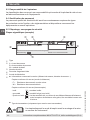
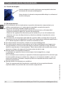
3.2 Locking screw
Always tighten the locking screw to prevent unintended opening
of the head with flameproof enclosure.
Before opening the head, always loosen the locking screw
sufficiently.
3.3 Electrical mounting
■
For the installation of the thermometer, only components (e.g. cables, cable glands,
etc.) permitted for “flameproof enclosure” may be used.
■
Using a transmitter/digital display (option):
- Observe the contents of these operating instructions and those of the transmitter/
digital display (see scope of delivery).
- Observe the relevant regulations for installation and use of electrical systems, and also
the regulations and guidelines for explosion protection.
■
The temperature resistance of the connection lead must match the permissible
operating temperature of the cases. For ambient temperatures above 60 °C,
heat-resistant connection leads must be used.
■
Do not fit any batteries into the flameproof case.
■
No capacitor may be fitted within the flameproof case that has a residual energy of
≥ 0.02 mJ at the end of the time required for opening the case. The case must not be
opened during operation. After the operating voltage has been switched off, a waiting
time of 2 minutes must be observed before opening the case.
■
Mounting within metal vessels:
The case must be grounded against electromagnetic fields and electrostatic charge.
It must not be connected separately to the equipotential bonding system. It is sufficient
if the metal thermowell has a solid and secured contact with the metal vessel or its
structural components or pipelines, so long as these components are connected to the
equipotential bonding system.
■
Mounting within non-metal vessels:
All electrically conductive thermometer components within the hazardous area must be
provided with equipotential bonding.
3. Commissioning, operation

EN
14280101.01 03/2019 EN/DE/FR/ES
WIKA additional information TR12/TC12, flameproof enclosure (Ex d) 9
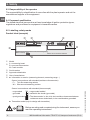
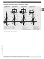
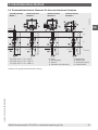
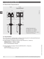
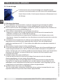
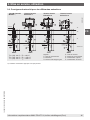
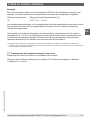
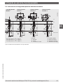
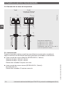
3.4 Safety-related instructions for the different variants
3. Commissioning, operation
TR12-B, TC12-B
Variant 1
TR12-B, TC12-B
Variant 2
TR12-B, TC12-B
Variant 3
Thread
TR12-M, TC12-M
Module
1)
Thread
Thread Thread Thread
Legend:
Connection head
Neck tube
Connection to thermowell
Measuring insert
Terminal block
Transmitter (option)
Field transmitter
14039769.01
T4
T3
T1
T
undefined
T4: (-50) -40 °C < T
a
< +80 °C
T3: (-50) -40 °C < T
a
< +150 °C
T1: (-50) -40 °C < T
a
< +300 °C
1) Use without suitable case is not permitted.

EN
14280101.01 03/2019 EN/DE/FR/ES
WIKA additional information TR12/TC12, flameproof enclosure (Ex d)10
3.4.1 Variant 1
The thermometer is fitted to a certified enclosure with “flameproof enclosure” ignition
protection type, which has a terminal block built into it. If the thermometer is marked with
II 2G Ex db IIC T1 ... T6 Gb, then it is designed for use in zone 1. If the thermometer is
marked with II 1/2G Ex ia IIC T1 ... T6 Ga/Gb, then it is designed for use with a thermowell
at the partition to zone 0.
▶
ATEX/IECEx Ex d case or connection head (with connection terminals, without
transmitter)
Evaluation of the resistance or the thermoelectric voltage by means of electronics outside
of the hazardous area.
Use in zone 1, marking II 2G Ex db IIC T1 ... T6 Gb
The flameproof case or the connection head is in zone 1 (or zone 2). The sensor is in
zone 1.
Use at the partition to zone 0, marking II 1/2G Ex db IIC T1 ... T6 Ga/Gb
The flameproof case or the connection head is in zone 1 (or zone 2). The sensor is within a
thermowell (min. wall thickness 1 mm) which extends into zone 0 via a process connection.
The thermometer should therefore be operated with a power-limiting circuit.
P
max
: 2 W
U
max
: 30 V
A power supply with Ex ia circuitry fulfills these conditions, but is not required if the limits
can be achieved through other measures. The responsibility rests with the operator.
A heating in the connection head does not occur with variant 1. However, an impermissible
heat reflux from the process which can exceed the operating temperature of the case or
the temperature class, must be prevented through suitable heat insulation or a suitably
long neck tube.
3. Commissioning, operation

EN
14280101.01 03/2019 EN/DE/FR/ES
WIKA additional information TR12/TC12, flameproof enclosure (Ex d) 11
3. Commissioning, operation
3.4.2 Variant 2
The thermometer is fitted to a certified enclosure with “flameproof enclosure” ignition
protection type, which has electronics built into it. If the thermometer is marked with
II 2G Ex db IIC T1 ... T6 Gb, then it is designed for use in zone 1. If the thermometer is
marked with II 1/2G Ex ia IIC T1 ... T6 Ga/Gb, then it is designed for use with a thermowell
at the partition to zone 0.
▶
ATEX/IECEx Ex d case or connection head with built-in head-mounted transmitter
The evaluation is made via a current (4 … 20 mA), voltage (0 … 10 V) or fieldbus signal,
which is generated from a head-mounted transmitter.
Use in zone 1, marking II 2G Ex db IIC T1 ... T6 Gb
The flameproof case or the connection head is in zone 1 (or zone 2). The sensor is in
zone 1.
Use at the partition to zone 0, marking II 1/2G Ex db IIC T1 ... T6 Ga/Gb
The flameproof case or the connection head is in zone 1 (or zone 2). The sensor is within a
thermowell (min. wall thickness 1 mm) which extends into zone 0 via a process connection.
The thermometer should be operated with a power-limiting circuit.
P
max
: 2 W
U
max
: 30 V
A power supply with Ex ia circuitry fulfils these conditions, but is not required if the limits
can be achieved through other measures. The responsibility rests with the operator.
WIKA recommends realising the power limitation through a suitable fuse in the 4 ... 20 mA
circuit of the head-mounted transmitter. In the event of a failure of the head-mounted
transmitter, the circuit will be interrupted through the fuse tripping.
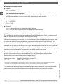
Example for calculating the fuse for a maximum power at the sensor of 0.8 W:
The internal resistance of thermocouples is significantly lower than the thermal resistance
of a Pt100 sensor, so the much less favourable case for a resistance thermometer has
been calculated.
P
max
= (1.7 x I
s
)² x Rw
I
s
= Fuse rating
P
max
= maximum power at sensor = 0.8 W
R
w
= Resistance of the sensor (temperature-dependent)
at 450 °C = 264.18 Ω in accordance with DIN EN 60751 for Pt100

EN
14280101.01 03/2019 EN/DE/FR/ES
WIKA additional information TR12/TC12, flameproof enclosure (Ex d)12
This results in the following fuse rating:
I
s
= sqrt (P
max
/ R
w
) / 1.7
I
s
= sqrt (0.8 W / 265 Ω) / 1.7
I
s
= 32.32 mA
This results in a rated current for a fuse link = 32 mA
Notes for fuse calculation:
The next smallest fuse value, in accordance with IEC 60127, must always be chosen. The
breaking capacity must be matched, by sensible engineering, to the voltage supply. Usual
values for such fuse links lie between AC 20 A and AC 80 A rated breaking capacity.
For a maximum power at the sensor of 0.5 W the following value is given:
I
s
= sqrt (0.5 W / 265 Ω) / 1.7
I
s
= 25.55 mA
This results in a rated current for a fuse link = 25 mA
When using multiple sensors and simultaneous operation, the sum of the individual powers
must not exceed the value of the maximum permissible power.
Internal resistance of Ø 6 mm TC measuring inserts: approx. 1.2 Ω/m
Internal resistance of Ø 3 mm TC measuring inserts: approx. 5.6 Ω/m
These measured values are valid for room temperature.
For all WIKA connection heads with built-in WIKA temperature transmitters, the
following interrelation is valid:
The temperature increase on the surface of the connection head or case is less than 25 K
if the following conditions are observed: Power supply U
B
maximum DC 30 V when the
transmitter is operated in a current limitation of 22.5 mA.
A heating in the connection head can occur with variant 2 through faulty electronics. The
permissible ambient temperatures depend on the case used and any additionally fitted
head-mounted transmitter.
However, an impermissible heat reflux from the process which can exceed the operating
temperature of the case or the temperature class, must be prevented through suitable heat
insulation or a suitably long neck tube.
3. Commissioning, operation

EN
14280101.01 03/2019 EN/DE/FR/ES
WIKA additional information TR12/TC12, flameproof enclosure (Ex d) 13
3.4.3 Variant 3
The thermometer is fitted to certified equipment (transmitter) with an ignition protection
type of “flameproof enclosure”. The thermometer is marked with II 2G Ex db IIC Tx Gb and
is designed for use in zone 1 with a thermowell. For any potential usage at the partition to
zone 0 with a thermowell, the approvals and conditions of the relevant transmitters must be
considered.
▶
ATEX/IECEx Ex d certified temperature transmitters
The evaluation is carried out via a current (4 … 20 mA), voltage (0 … 10 V) or fieldbus
signal, which is generated by an ATEX/IECEx Ex d certified temperature transmitter.
Only field transmitters listed by name in the Appendix of the Ex d certificate may be used.
Use in zone 1, marking II 2G Ex db IIC Gb
The flameproof case or the connection head is in zone 1 (or zone 2). The sensor is in
zone 1. In the case of a separation of Ex zones, a thermowell (from corrosion-resistant
steel, min. wall thickness 1 mm) must be used.
The main marking for models TR12-B and TC12-B are found on the certified connection
housing or Ex d field transmitter. The TR12-M and TC12-M modules are marked through a
foil plate on the neck tube.
For a possible use at the partition to zone 0 with a thermowell, the approvals and
conditions of the relevant Ex d field transmitters must be followed.
3.5 Electrical mounting
Using a transmitter/digital display (option):
Observe the contents of the operating instructions for the transmitter/digital display (see
scope of delivery).
Built-in transmitters/digital displays have their own EC-type examination certificate. The
permissible ambient temperature ranges of built-in transmitters can be taken from the
corresponding transmitter approval.
Observe the special conditions (see chapter 4 “Special conditions for use (X conditions)”,
point 5).
3. Commissioning, operation

EN
14280101.01 03/2019 EN/DE/FR/ES
WIKA additional information TR12/TC12, flameproof enclosure (Ex d)14
Electrical connection values
■
Variant 1
U
max
= DC 30 V
Use in methane atmospheres
Owing to the higher minimum ignition energy of methane, the instruments can also be
used where methane causes a potentially explosive gas atmosphere.
■
Variant 2
U
max
= DC 30 V
P
max
= 2 W
■
Variant 3
U
max
= depending on the transmitter/digital display
P
max
= in the case: depending on the transmitter/digital display
3.6 Temperature class classification, ambient temperatures
The permissible ambient temperatures depend on the temperature class, the cases used
and the optional built-in transmitter and/or digital display.
When a thermometer is connected to a transmitter and/or a digital display, the lowest value
of either the ambient temperature limits or the highest temperature class will apply. The
lower temperature limit is -40 °C; and -50 °C for special designs.
Where there are neither transmitters nor digital displays mounted within the case, there will
also be no additional warming. With a built-in transmitter (optionally with digital display),
heating caused by operating the transmitter or digital display may occur.
For applications without transmitters (digital displays) requiring instruments of equipment
group II (potentially explosive gas atmospheres), the following temperature class
classification and ambient temperature ranges apply:
Temperature class Ambient temperature range (T
a
)
T1 ... T6 (-50)
1)
-40 … +80 °C
1) The values in brackets apply to special designs. These probes are manufactured using special sealing compounds.
Moreover, they feature cases made of stainless steel and cable glands for low-temperature ranges.
The permissible ambient temperatures and surface temperatures for third-party products
can be seen from the relevant approvals and/or data sheets and must be observed.
3. Commissioning, operation

EN
14280101.01 03/2019 EN/DE/FR/ES
WIKA additional information TR12/TC12, flameproof enclosure (Ex d) 15
Example
For instruments fitted with a DIH50 transmitter and digital display, for example, the following
limit for temperature class classification applies:
Temperature class Ambient temperature range (T
a
)
T6 (-50)
1)
-40 … +60 °C
The permissible ambient temperatures and surface temperatures for third-party products
can be seen from the relevant approvals and/or data sheets and must be observed.
According to approval, these thermometers are suitable for the temperature classes
T1 ... T6. This applies for instruments with or without built-in transmitters and/or digital
displays. Make sure the maximal ambient temperature for the safe use of the instrument is
not exceeded.
1) The values in brackets apply to special designs. These probes are manufactured using special sealing compounds.
Moreover, they feature cases made of stainless steel and cable glands for low-temperature ranges.
3.7 Temperature carry-over from the process
Prevent any heat reflux from the process!
Observe the special conditions (see chapter 4 “Special conditions for use (X conditions)”,
point 3).
3. Commissioning, operation

EN
14280101.01 03/2019 EN/DE/FR/ES
WIKA additional information TR12/TC12, flameproof enclosure (Ex d)16
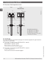
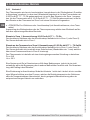
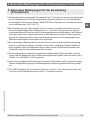
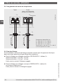
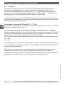
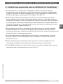
3.8 Overview of the temperature zones
3.9 Thread gap
For fitting, the following permitted thread gaps for electrical equipment for gas hazardous
areas must be maintained:
■
Thread gap for parallel threads (IEC/EN 60079-1, table 4):
Case volumes < 100 cm³: ≥ 5 mm
Case volumes > 100 cm³: ≥ 8 mm
There must be at least 5 threads engaged
■
Thread gap for tapered threads (IEC/EN 60079-1, table 5):
on each component ≥ 5
There must be at least 4.5 threads engaged
FF-00147.00
Tx12
Tx12
Option: with built-in
transmitter e.g. T32
Tx12-A
Tx12-A
T3
T3
Process connection
Process connection
1)
Permissible temperatures at
T1: (-50) -40 °C < T
a
< +300 °C
T3: (-50) -40 °C < T
a
< +150 °C
T4: (-50) -40 °C < T
a
< +80 °C
T4
Transmitter
: (-50) -40 °C < Ta < +80 °C
1) Temperature zone undefined
T4
T4
Transmitter
T1 T1
1)
3. Commissioning, operation

EN
14280101.01 03/2019 EN/DE/FR/ES
WIKA additional information TR12/TC12, flameproof enclosure (Ex d) 17
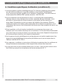
4. Special conditions for use (X conditions)
1)
The certified flameproof thermometers model Tx12 should only be fitted to cases certified
with a “flameproof enclosure” ignition protection type. The certified cases to be used
can be found in the Appendix “WIKA ATEX Ex d case and instrument listings” (article
number: 14011281.07)
2)When using thermometers in zone 0, an additional thermowell (made of corrosion-
resistant steel, wall thickness min. 1 mm) must isolate the thermometer from the medium
to be measured and a fuse must be connected upstream in the supply as power-limiting
measure. Perform dimensioning of the fuse as a function of the temperature class,
process temperature and the power supply (for calculation examples, see chapter 5).
3)An inadmissible heat reflux from the process must be prevented, for example, by heat
insulation or an extended neck tube. An inadmissible heat reflux occurs when the heat
input from the process exceeds the operating temperature of the case or the temperature
class.
4)The joint lengths of the flameproof joint of this equipment are sometimes longer and
the joint widths of the flameproof joint are sometimes smaller than required in Table 3 of
EN 60079-1:2014.
5)The requirements/conditions or instructions for use listed in the certificates of each
instrument (transmitter) and enclosure must be observed.
6)
The WIKA case model connection box series 5 and series 7 with inserted glass may only
be operated up to an operating temperature of 80 °C.
4. Special conditions for use (X conditions)

EN
14280101.01 03/2019 EN/DE/FR/ES
WIKA additional information TR12/TC12, flameproof enclosure (Ex d)18
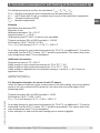
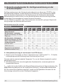
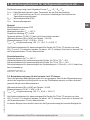
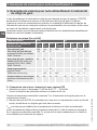
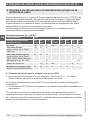
5. Calculation examples for self-heating at the thermowell tip
The self-heating at the thermowell tip depends upon the sensor type (TC/RTD), the
measuring insert diameter and the thermowell design. The table below shows the possible
combinations. The heating at the probe tip of the bare measuring insert is clearly higher;
the representation of these values was omitted on the grounds of the required assembly
with a thermowell.
The table shows that thermocouples generate much less self-heating than resistance
thermometers.
Thermal resistance [R
th
in K/W]
Sensor type RTD TC
Measuring insert diameter
in mm
2.0 -
< 3.0
3.0 -
≤6.0
6 - 8 3.0 -
6.0 mm
5
0.5 -
< 1.5
1.5 -
< 3.0
3.0 -
< 6.0
6.0 -
12.0
Without thermowell 245 110 75 225 105 60 20 5
With fabricated thermowell
(straight and tapered), e.g. TW35,
TW40 etc.
135 60 37 - - - 11 2.5
With thermowell - solid-body
material (straight and tapered),
e.g. TW10, TW15, TW20, TW25,
TW30 etc.
50 22 16 - - - 4 1
Special thermowell
per EN 14597
- - 33 - - - - 2.5
Tx55 (retaining tube) - 110 75 225 - - 20 5
Built into a blind bore
(minimum wall thickness 5 mm)
50 22 16 45 22 13 4 1
5.1 Example calculation for variant 2 with RTD sensor
▶
Use at the partition to zone 0, marking II 1/2G Ex db IIC T1 ... T6 Ga/Gb
Power-limiting circuit using a fuse with 32 mA
Calculate the maximum possible temperature, T
max
, at the thermowell tip for the following
combination:
▶
Ø 6 mm RTD measuring insert with built-in head-mounted transmitter, assembled with
solid-machined thermowell
T
max
is obtained by adding the temperature of the medium and the self-heating. The
self-heating depends on the supplied power P
o
and the thermal resistance R
th
. The
calculated supplied power, P
o
, comes from the chosen standard value for the fuse and is
only realised at the probe tip.
5. Calculation examples for self-heating at the thermowell tip

EN
14280101.01 03/2019 EN/DE/FR/ES
WIKA additional information TR12/TC12, flameproof enclosure (Ex d) 19
The following formula is used for the calculation: T
max
= P
o
* R
th
+ T
M
T
max
= Surface temperature (max. temperature at the thermowell tip)
P
o
= 0.8 W (fuse with 32 mA, a complete short-circuit of the transmitter is assumed)
R
th
= Thermal resistance [K/W]
T
M
= Medium temperature
Example
Resistance thermometer RTD
Diameter: 6 mm
Medium temperature: T
M
= 150 °C
Supplied power: P
o
= 0.8 W
Temperature class T3 (200 °C) must not be exceeded
Thermal resistance [R
th
in K/W] from table = 16 K/W
Self-heating: 0.8 W * 16 K/W = 12.8 K
T
max
= T
M
+ self-heating: 150 °C + 12.8 °C = 162.8 °C
As a safety margin for type-tested instruments (for T6 to T3), an additional 5 °C must be
subtracted from the 200 °C; hence 195 °C would be permissible. This means that in this
case temperature class T3 is not exceeded.
Additional information:
Temperature class for T3 = 200 °C
Safety margin for type-tested instruments (for T3 to T6)
1)
= 5 K
Safety margin for type-tested instruments (for T1 to T2)
1)
= 10 K
Safety margin for applications for instrument category 1 (zone 0)
2)
= 80 % finds no
application here
1) EN 60079-0 section 26.5.1.3
2) EN 1127-1: 2011 section 6.4.2
5.2 Example calculation for variant 2 with TC sensor
Under the same conditions it gives a lower value for the self-heating, since the supplied
power is not only converted at the probe tip, but rather over the entire length of the
measuring insert.
Thermal resistance [R
th
in K/W] from table = 3 K/W
Self-heating: 0.8 W * 1 K/W = 0.8 K
T
max
= T
M
+ self-heating: 150 °C + 0.8 K = 150.8 °C
As a safety margin for type-tested instruments (for T6 to T3), an additional 5 °C must be
subtracted from the 200 °C; hence 195 °C would be permissible. This means that in this
case temperature class T3 is not exceeded.
In this example it is clear that the self-heating here is almost negligible.
5. Calculation examples for self-heating at the thermowell tip

EN
14280101.01 03/2019 EN/DE/FR/ES
WIKA additional information TR12/TC12, flameproof enclosure (Ex d)20
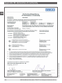
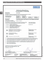
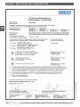
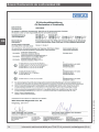
Appendix: EU declaration of conformity
La page est en cours de chargement...
La page est en cours de chargement...
La page est en cours de chargement...
La page est en cours de chargement...
La page est en cours de chargement...
La page est en cours de chargement...
La page est en cours de chargement...
La page est en cours de chargement...
La page est en cours de chargement...
La page est en cours de chargement...
La page est en cours de chargement...
La page est en cours de chargement...
La page est en cours de chargement...
La page est en cours de chargement...
La page est en cours de chargement...
La page est en cours de chargement...
La page est en cours de chargement...
La page est en cours de chargement...
La page est en cours de chargement...
La page est en cours de chargement...
La page est en cours de chargement...
La page est en cours de chargement...
La page est en cours de chargement...
La page est en cours de chargement...
La page est en cours de chargement...
La page est en cours de chargement...
La page est en cours de chargement...
La page est en cours de chargement...
La page est en cours de chargement...
La page est en cours de chargement...
La page est en cours de chargement...
La page est en cours de chargement...
La page est en cours de chargement...
La page est en cours de chargement...
La page est en cours de chargement...
La page est en cours de chargement...
La page est en cours de chargement...
La page est en cours de chargement...
La page est en cours de chargement...
La page est en cours de chargement...
La page est en cours de chargement...
La page est en cours de chargement...
La page est en cours de chargement...
La page est en cours de chargement...
La page est en cours de chargement...
La page est en cours de chargement...
La page est en cours de chargement...
La page est en cours de chargement...
La page est en cours de chargement...
La page est en cours de chargement...
La page est en cours de chargement...
La page est en cours de chargement...
La page est en cours de chargement...
La page est en cours de chargement...
La page est en cours de chargement...
La page est en cours de chargement...
-
 1
1
-
 2
2
-
 3
3
-
 4
4
-
 5
5
-
 6
6
-
 7
7
-
 8
8
-
 9
9
-
 10
10
-
 11
11
-
 12
12
-
 13
13
-
 14
14
-
 15
15
-
 16
16
-
 17
17
-
 18
18
-
 19
19
-
 20
20
-
 21
21
-
 22
22
-
 23
23
-
 24
24
-
 25
25
-
 26
26
-
 27
27
-
 28
28
-
 29
29
-
 30
30
-
 31
31
-
 32
32
-
 33
33
-
 34
34
-
 35
35
-
 36
36
-
 37
37
-
 38
38
-
 39
39
-
 40
40
-
 41
41
-
 42
42
-
 43
43
-
 44
44
-
 45
45
-
 46
46
-
 47
47
-
 48
48
-
 49
49
-
 50
50
-
 51
51
-
 52
52
-
 53
53
-
 54
54
-
 55
55
-
 56
56
-
 57
57
-
 58
58
-
 59
59
-
 60
60
-
 61
61
-
 62
62
-
 63
63
-
 64
64
-
 65
65
-
 66
66
-
 67
67
-
 68
68
-
 69
69
-
 70
70
-
 71
71
-
 72
72
-
 73
73
-
 74
74
-
 75
75
-
 76
76


WIKA TR12-B D Serie, TC12-B D Serie Manuel utilisateur
- Taper
- Manuel utilisateur
- Ce manuel convient également à
dans d''autres langues
Documents connexes
-
WIKA TC12-A tag:model:TC12-B tag:model:TC12-M tag:model:TR12-A tag:model:TR12-B tag:model:TR12-M Mode d'emploi
-
-
-
-
-
-
-
-
-