


FlatClient ECO and FlatClient PRO, FlatClient RCK and FlatClient STS – User Guide Rev. 2.4
www.kontron.com // 3
FLATCLIENT ECO AND F
LATCLIENT PRO, FLATCLIENT RCK
AND FLATCLIENT STS
– USER GUIDE
Disclaimer
Kontron would like to point out that the information contained in this user guide may be subject to alteration,
particularly as a result of the constant upgrading of Kontron products. This document does not entail any guarantee on
the part of Kontron with respect to technical processes described in the user guide or any product characteristics set
out in the user guide. Kontron assumes no responsibility or liability for the use of the described product(s), conveys no
license or title under any patent, copyright or mask work rights to these products and makes no representations or
warranties that these products are free from patent, copyright or mask work right infringement unless otherwise
specified. Applications that are described in this user guide are for illustration purposes only. Kontron makes no
representation or warranty that such application will be suitable for the specified use without further testing or
modification. Kontron expressly informs the user that this user guide only contains a general description of processes
and instructions which may not be applicable in every individual case. In cases of doubt, please contact Kontron.
This user guide is protected by copyright. All rights are reserved by Kontron. No part of this document may be
reproduced, transmitted, transcribed, stored in a retrieval system, or translated into any language or computer
language, in any form or by any means (electronic, mechanical, photocopying, recording, or otherwise), without the
express written permission of Kontron. Kontron points out that the information contained in this user guide is
constantly being updated in line with the technical alterations and improvements made by Kontron to the products and
thus this user guide only reflects the technical status of the products by Kontron at the time of publishing.
Brand and product names are trademarks or registered trademarks of their respective owners.
©2022 by Kontron Europe GmbH
Kontron Europe GmbH
Gutenbergstraße 2
85737 Ismaning
Germany
www.kontron.com

FlatClient ECO and FlatClient PRO, FlatClient RCK and FlatClient STS – User Guide Rev. 2.4
www.kontron.com // 4
Intended Use
THIS DEVICE AND ASSOCIATED SOFTWARE ARE NOT DESIGNED, MANUFACTURED OR INTENDED FOR USE
OR RESALE FOR THE OPERATION OF NUCLEAR FACILITIES, THE NAVIGATION, CONTROL OR
COMMUNICATION SYSTEMS FOR AIRCRAFT OR OTHER TRANSPORTATION, AIR TRAFFIC CONTROL, LIFE
SUPPORT OR LIFE SUSTAINING APPLICATIONS, WEAPONS SYSTEMS, OR ANY OTHER APPLICATION IN A
HAZARDOUS ENVIRONMENT, OR REQUIRING FAIL-SAFE PERFORMANCE, OR IN WHICH THE FAILURE OF
PRODUCTS COULD LEAD DIRECTLY TO DEATH, PERSONAL INJURY, OR SEVERE PHYSICAL OR
ENVIRONMENTAL DAMAGE (COLLECTIVELY, “HIGH RISK APPLICATIONS”).
You understand and agree that your use of Kontron devices as a component in High Risk Applications is entirely at
your risk. To minimize the risks associated with your products and applications, you should provide adequate design
and operating safeguards. You are solely responsible for compliance with all legal, regulatory, safety, and security
related requirements concerning your products. You are responsible to ensure that your systems (and any Kontron
hardware or software components incorporated in your systems) meet all applicable requirements. Unless otherwise
stated in the product documentation, the Kontron device is not provided with error-tolerance capabilities and cannot
therefore be deemed as being engineered, manufactured or setup to be compliant for implementation or for resale as
device in High Risk Applications. All application and safety related information in this document (including application
descriptions, suggested safety measures, suggested Kontron products, and other materials) is provided for reference
only.
Handling and operation of the product is permitted only for trained personnel within a work
place that is access controlled. Please follow the “General Safety Instructions” supplied with
the system.
You find the most recent version of the “General Safety Instructions“ online in the download
area of this product.
This product is not suited for storage or operation in corrosive environments, in particular
under exposure to sulfur and chlorine and their compounds. For information on how to
harden electronics and mechanics against these stress conditions, contact Kontron Support.

FlatClient ECO and FlatClient PRO, FlatClient RCK and FlatClient STS – User Guide Rev. 2.4
www.kontron.com // 5
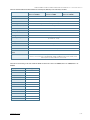
Revision History
Revision Brief Description of Changes Date of Issue Author
1.6 Initial Issue 2017-July-12 hjs
1.7 Added Skylake and Kaby Lake variants 2018-June-29 hjs
1.8 Changed the 15” built-in mechanical diagrams 2018-Oct-02 CW
1.9 Added 10.1”, 12.2” and 13.3” chapter, added Apollo Lake variants, changed Power-in
to 12-30VDC, Added French safety instructions
2019-Mar-21 hjs
1.92 Photo optimization in Table 2 2019-Jul-16 hjs
1.93 10.1” full metal variant integrated 2020-Feb-05 hjs
1.94 Torque moment added, TPM function added, slim variants added, changed UL
62368 in chapter 3/new type label
2020-Jul-13 hjs
1.95 7”-Version integrated, “General Safety Instructions “ updated, Notice “cabinet
doors thickness” in chapter 9.1 integrated
2020-Oct-13 hjs
1.96 UL content for General Safety Instructions added, Notice “Sunlit environment”
inserted
2020-Nov-23 hjs
1.97 STS/RCK introduced, Order information modified, new certification reports in
Table 1, Table 16 and Table 17, RFID Chapter 9.3 added
2021-Feb-23 hjs
1.98 Word2016 issues 2021-Mar-16 hjs
1.99 New Dimension Drawing 7”- and 21.5-monitor, chipset J3455 and Whiskey Lake
added, brightness in Table 6 corrected
2021-May-16 hjs
2.0 Updated Installation instructions 2021-Aug-09 CW
2.1 18,5” Panel Cutout added in chapter 7.22.1 2022-Jan-11 hjs
2.2 Exchange of figures in chapter 7.9, 7.13.1, 7.21, 7.27, 7.28, 7.31 2022-May-11 hjs
2.3 Extended Chapter 9.4 Startup Procedure, changed 15” brightness value, 13.3”
dimensions in Table 5, added panel cutout dimensions in Chapter 7 and updated
Type label with new logo.
2022-Apr-19 CW
2.4 Removed Ubuntu and added new logo. 2023-Sept-06 CW
Terms and Conditions
Kontron warrants products in accordance with defined regional warranty periods. For more information about
warranty compliance and conformity, and the warranty period in your region, visit http://www.kontron.com/terms-
and-conditions.
Kontron sells products worldwide and declares regional General Terms & Conditions of Sale, and Purchase Order Terms
& Conditions. Visit http://www.kontron.com/terms-and-conditions.
For contact information, refer to the corporate offices contact information on the last page of this user guide or visit
our website CONTACT US.
Customer Support
Find Kontron contacts by visiting https://www.kontron.com/support-and-services.
Customer Service
As a trusted technology innovator and global solutions provider, Kontron extends its embedded market strengths into
a services portfolio allowing companies to break the barriers of traditional product lifecycles. Proven product expertise
coupled with collaborative and highly-experienced support enables Kontron to provide exceptional peace of mind to
build and maintain successful products.

FlatClient ECO and FlatClient PRO, FlatClient RCK and FlatClient STS – User Guide Rev. 2.4
www.kontron.com // 6
For more details on Kontron’s service offerings such as: enhanced repair services, extended warranty, Kontron training
academy, and more visit https://www.kontron.com/support-and-services.
Customer Comments
If you have any difficulties using this user guide, discover an error, or just want to provide some feedback, contact
Kontron support. Detail any errors you find. We will correct the errors or problems as soon as possible and post the
revised user guide on our website.

FlatClient ECO and FlatClient PRO, FlatClient RCK and FlatClient STS – User Guide Rev. 2.4
www.kontron.com // 7
Symbols
The following symbols may be used in this user guide
DANGER indicates a hazardous situation which, if not avoided,
will result in death or serious injury.
WARNING indicates a hazardous situation which, if not avoided,
could result in death or serious injury.
NOTICE indicates a property damage message.
CAUTION indicates a hazardous situation which, if not avoided,
may result in minor or moderate injury.
Electric Shock!
This symbol and title warn of hazards due to electrical shocks (> 60
V) when touching
products or parts of products. Failure to observe the precautions indicated and/or prescribed
by the law may endanger your life/health and/or result in damage to your material.
ESD Sensitive Device!
This symbol and title inform that the electronic boards and their components are sensitive to
static electricity. Care must therefore be taken during all handling operations and inspections
of this product in order to ensure product integrity at all times.
HOT Surface!
Do NOT touch! Allow to cool before servicing.
Laser!
This symbol inform of the risk of exposure to laser beam and light emitting devices (LEDs)
from an electrical device. Eye protection per manufacturer notice shall review before
servicing.
This symbol indicates general information about the product and the user guide.
This symbol also indicates detail information about the specific product configuration.
This symbol precedes helpful hints and tips for daily use.

FlatClient ECO and FlatClient PRO, FlatClient RCK and FlatClient STS – User Guide Rev. 2.4
www.kontron.com // 8
For Your Safety
Your new Kontron product was developed and tested carefully to provide all features necessary to ensure its
compliance with electrical safety requirements. It was also designed for a long fault-free life. However, the life
expectancy of your product can be drastically reduced by improper treatment during unpacking and installation.
Therefore, in the interest of your own safety and of the correct operation of your new Kontron product, you are
requested to conform with the following guidelines.
High Voltage Safety Instructions
As a precaution and in case of danger, the power connector must be easily accessible. The power connector is the
product’s main disconnect device.
Warning
All operations on this product must be carried out by sufficiently skilled personnel only.
Electric Shock!
Before installing a non hot-swappable Kontron product into a system always ensure that
your mains power is switched off. This also applies to the installation of piggybacks. Serious
electrical shock hazards can exist during all installation, repair, and maintenance operations
on this product. Therefore, always unplug the power cable and any other cables which
provide external voltages before performing any work on this product.
Earth ground connection to vehicle’s chassis or a central grounding point shall remain
connected. The earth ground cable shall be the last cable to be disconnected or the first
cable to be connected when performing installation or removal procedures on this product.
Special Handling and Unpacking Instruction
ESD Sensitive Device!
Electronic boards and their components are sensitive to static electricity. Therefore, care
must be taken during all handling operations and inspections of this product, in order to
ensure product integrity at all times.
Handling and operation of the product is permitted only for trained personnel within a work
place that is access controlled. Follow the “General Safety Instructions” supplied with the
product.
Do not handle this product out of its protective enclosure while it is not used for operational purposes unless it is
otherwise protected.
Whenever possible, unpack or pack this product only at EOS/ESD safe work stations. Where a safe work station is not
guaranteed, it is important for the user to be electrically discharged before touching the product with his/her hands
or tools. This is most easily done by touching a metal part of your system housing.
It is particularly important to observe standard anti-static precautions when changing piggybacks, ROM devices,
jumper settings etc. If the product contains batteries for RTC or memory backup, ensure that the product is not placed
on conductive surfaces, including anti-static plastics or sponges. They can cause short circuits and damage the
batteries or conductive circuits on the product.

FlatClient ECO and FlatClient PRO, FlatClient RCK and FlatClient STS – User Guide Rev. 2.4
www.kontron.com // 9
Lithium Battery Precautions
If your product is equipped with a lithium battery, take the following precautions when replacing the battery.
Risk of Explosion if Battery is replaced by an incorrect Type. Dispose of used batteries
According to the instructions.
Risque d’explosion si la batterie est remplacée par un type incorrect. Mettre au rebus les
batteries usagées selon les instructions.
General Instructions on Usage
In order to maintain Kontron’s product warranty, this product must not be altered or modified in any way. Changes or
modifications to the product, that are not explicitly approved by Kontron and described in this user guide or received
from Kontron Support as a special handling instruction, will void your warranty.
This product should only be installed in or connected to systems that fulfill all necessary technical and specific
environmental requirements. This also applies to the operational temperature range of the specific board version
that must not be exceeded. If batteries are present, their temperature restrictions must be taken into account.
In performing all necessary installation and application operations, only follow the instructions supplied by the
present user guide.
Keep all the original packaging material for future storage or warranty shipments. If it is necessary to store or ship
the product then re-pack it in the same manner as it was delivered.
Special care is necessary when handling or unpacking the product. See Special Handling and Unpacking Instruction.
Quality and Environmental Management
Kontron aims to deliver reliable high-end products designed and built for quality, and aims to complying with
environmental laws, regulations, and other environmentally oriented requirements. For more information regarding
Kontron’s quality and environmental responsibilities, visit http://www.kontron.com/about-kontron/corporate-
responsibility/quality-management.
Disposal and Recycling
Kontron’s products are manufactured to satisfy environmental protection requirements where possible. Many of the
components used are capable of being recycled. Final disposal of this product after its service life must be
accomplished in accordance with applicable country, state, or local laws or regulations.
WEEE Compliance
The Waste Electrical and Electronic Equipment (WEEE) Directive aims to:
Reduce waste arising from electrical and electronic equipment (EEE)
Make producers of EEE responsible for the environmental impact of their products, especially when the product
become waste
Encourage separate collection and subsequent treatment, reuse, recovery, recycling and sound environmental
disposal of EEE
Improve the environmental performance of all those involved during the lifecycle of EEE
Environmental protection is a high priority with Kontron.
Kontron follows the WEEE directive
You are encouraged to return our products for proper disposal.

FlatClient ECO and FlatClient PRO, FlatClient RCK and FlatClient STS – User Guide Rev. 2.4
www.kontron.com // 10
Table of Contents
Symbols ................................................................................................................................................................................................................. 7
For Your Safety ................................................................................................................................................................................................... 8
High Voltage Safety Instructions ................................................................................................................................................................. 8
Special Handling and Unpacking Instruction ........................................................................................................................................... 8
Lithium Battery Precautions ........................................................................................................................................................................... 9
General Instructions on Usage....................................................................................................................................................................... 9
Quality and Environmental Management .................................................................................................................................................. 9
Disposal and Recycling ..................................................................................................................................................................................... 9
WEEE Compliance............................................................................................................................................................................................... 9
Table of Contents ............................................................................................................................................................................................. 10
List of Tables ...................................................................................................................................................................................................... 12
List of Figures .................................................................................................................................................................................................... 13
1/ Introduction .......................................................................................................................................................................................... 15
2/ General Safety Instructions ............................................................................................................................................................ 16
2.1. UL Canada: Instructions générales de sécurité ............................................................................................................................... 17
2.2. Electromagnetic Compatibility EU ...................................................................................................................................................... 18
2.3. Electrostatic Discharge (ESD) .............................................................................................................................................................. 19
2.3.1. Grounding Methods .............................................................................................................................................................................. 19
3/ Scope of Delivery ............................................................................................................................................................................... 20
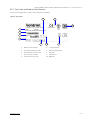
3.1.1. Type Label and Product Identification ............................................................................................................................................ 22
4/ Product Features ............................................................................................................................................................................... 23
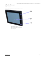
4.1. Front Features .......................................................................................................................................................................................... 23
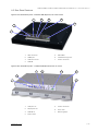
4.2. Rear Panel Features ............................................................................................................................................................................... 24
5/ Order Information.............................................................................................................................................................................. 25
6/ Product Specification ....................................................................................................................................................................... 28
6.1. Technical Specification........................................................................................................................................................................... 28
6.2. Environmental Specification................................................................................................................................................................ 34
6.3. Power Specification ................................................................................................................................................................................ 34
6.4. Compliance ................................................................................................................................................................................................ 35
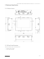
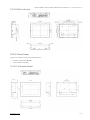
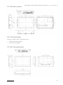
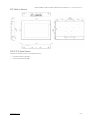
7/ Mechanical Specification ................................................................................................................................................................ 36
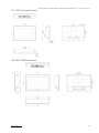
7.1. 7.0“ Built-in Variant .................................................................................................................................................................................. 36
7.2. 7.0"Panel Cutout Dimensions .............................................................................................................................................................. 36
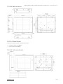
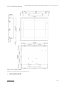
7.3. 10.1“ Built-in Variant ................................................................................................................................................................................ 37
7.3.1. 10.1"Panel Cutout ................................................................................................................................................................................... 37
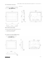
7.4. 10.1“ Full-metal Variant ......................................................................................................................................................................... 37
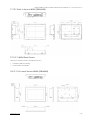
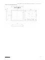
7.5. 10.4“ Built-in Variant ............................................................................................................................................................................... 38
7.5.1. 10.4" Panel Cutout ................................................................................................................................................................................. 38
7.6. 10.4“ Full-metal Variant......................................................................................................................................................................... 38
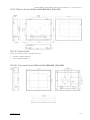
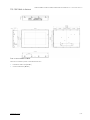
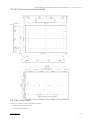
7.7. 12.1“ Built-in Variant WXGA (1280x800) ........................................................................................................................................... 39
7.7.1. 12.1" WXGA Panel Cutout ..................................................................................................................................................................... 39
7.8. 12.1“ Full-metal Variant WXGA (1280x800) .................................................................................................................................... 39
7.9. 12.1“ Built-in Variant SVGA and XGA (800x600, 1024x768) ....................................................................................................... 40
7.9.1. 12.1" Panel Cutout .................................................................................................................................................................................. 40
7.10. 12.1“ Full-metal Variant SVGA and XGA (800x600, 1024x768) ............................................................................................... 40
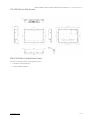
7.11. 13.3“ Built-in Variant ............................................................................................................................................................................... 41
7.11.1. 13.3" Panel Cutout ................................................................................................................................................................................. 41
7.12. 13.3“ Full-metal Variant ........................................................................................................................................................................ 41

FlatClient ECO and FlatClient PRO, FlatClient RCK and FlatClient STS – User Guide Rev. 2.4
www.kontron.com // 11
7.13. 15.0“ Built-in Variant ............................................................................................................................................................................. 42
7.13.1. 15.0" Panel Cutout ............................................................................................................................................................................... 42
7.14. 15.0“ Full-metal VESA Variant ............................................................................................................................................................ 42
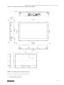
7.15. 15.6“ Built-in Variant .............................................................................................................................................................................. 43
7.15.1. 15.6" Panel Cutout ................................................................................................................................................................................ 43
7.16. 15.6“ Built-in Slim Variant .................................................................................................................................................................... 44
7.16.1. 15.6” Built-in (slim) Panel Cutout ................................................................................................................................................... 44
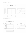
7.17. 15.6“ Full-metal Variant........................................................................................................................................................................ 45
7.18. 15.6“ VESA Slim Variant ........................................................................................................................................................................ 45
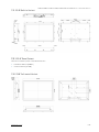
7.19. 17.0“ Built-in Variant ............................................................................................................................................................................. 46
7.19.1. 17.0" Panel Cutout................................................................................................................................................................................ 46
7.20. 17.0“ Full-metal Variant ...................................................................................................................................................................... 47
7.21. 18.5“ Built-in Variant (HD and FullHD) ............................................................................................................................................. 48
7.21.1. 18.5" Panel Cutout ............................................................................................................................................................................... 48
7.22. 18.5“ Built-in Slim Variant (HD and FullHD) .................................................................................................................................. 49
7.22.1. 18.5" Panel Cutout ............................................................................................................................................................................... 49
7.23. 18.5“ Full-metal VESA Variant (HD and FullHD) .......................................................................................................................... 50
7.24. 18.5“ VESA Slim Variant (HD and FullHD) ...................................................................................................................................... 50
7.25. 19.0“ Built-in Variant.............................................................................................................................................................................. 51
7.25.1. 19.0" Panel Cutout ................................................................................................................................................................................ 51
7.26. 19.0“ Full-metal VESA Variant ........................................................................................................................................................... 52
7.27. 19” Monitor Rackmount (RCK)21.5“ Built-in Variant ................................................................................................................... 52
7.27.1. 21.5" Panel Cutout ............................................................................................................................................................................... 53
7.28. 21.5“ Built-in Slim Variant (HD and FullHD) .................................................................................................................................. 54
7.28.1. 21.5" Slim Variant Panel Cutout ...................................................................................................................................................... 54
7.29. 21.5“ Full-metal Variant....................................................................................................................................................................... 55
7.30. 21.5“ VESA Slim Variant ....................................................................................................................................................................... 55
7.31. 23.8“ Built-in Variant ............................................................................................................................................................................ 56
7.31.1. 23.8 "Panel Cutout ............................................................................................................................................................................... 56
7.32. 23.8“ Full-metal Variant...................................................................................................................................................................... 56
8/ Connectors ............................................................................................................................................................................................ 57
8.1. FlatClient ECO Intel BayTrail J1900 ...................................................................................................................................................... 57
8.2. FlatClient ECO Intel BayTrail J1900 7" Variant ................................................................................................................................. 57
8.2.1. Input Power Connector ....................................................................................................................................................................... 58
8.2.2. Power-Switch and LEDs .................................................................................................................................................................... 58
8.2.3. USB2.0 Type-A Connector................................................................................................................................................................. 59
8.2.4. USB3.0 Type-A Connector ................................................................................................................................................................ 59
8.2.5. GbE RJ-45 Connector .......................................................................................................................................................................... 59
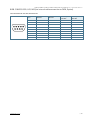
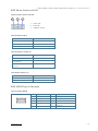
8.2.6. LED Diagram of LAN Connectors .................................................................................................................................................... 59
8.2.7. HDMI Connector .................................................................................................................................................................................... 60
8.2.8. DB15 VGA Connector ........................................................................................................................................................................... 60
8.2.9. COM2 RS-232/422/485 (via internal cable connection to CN16, Option) ......................................................................... 61
8.3. FlatClient ECO Apollo Lake N4200/Intel® Celeron® J3455 ........................................................................................................ 62
8.3.1. Input Power Connector ....................................................................................................................................................................... 62
8.3.2. Power-Switch and LEDs .................................................................................................................................................................... 63
8.3.3. USB2.0 Type-A Connector................................................................................................................................................................. 63
8.3.4. USB3.0 Type-A Connector ................................................................................................................................................................ 64
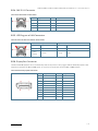
8.3.5. GbE RJ-45 Connector .......................................................................................................................................................................... 64
8.3.6. LED Diagram of LAN Connectors .................................................................................................................................................... 64

FlatClient ECO and FlatClient PRO, FlatClient RCK and FlatClient STS – User Guide Rev. 2.4
www.kontron.com // 12
8.3.7. HDMI Connector .................................................................................................................................................................................... 65
8.3.8. DB15 VGA Connector ........................................................................................................................................................................... 65
8.3.9. COM2 RS-232/422/485 (via internal cable connection to CN16, Option) ........................................................................ 66
8.4. FlatClient PRO Haswell.......................................................................................................................................................................... 67
8.4.1. Input Power Connector ....................................................................................................................................................................... 67
8.4.2. Power-Switch and LEDs .................................................................................................................................................................... 68
8.4.3. USB3.0 Type-A Connector ................................................................................................................................................................ 68
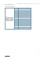
8.4.4. GbE RJ-45 Connector .......................................................................................................................................................................... 69
8.4.5. LED Diagram of LAN Connectors .................................................................................................................................................... 69
8.4.6. DisplayPort Connector ....................................................................................................................................................................... 69
8.4.7. COM2 RS-232/422/485 (via internal cable connection to CN16, Option) ........................................................................ 70
8.5. FlatClient PRO Skylake/Kaby Lake/Whiskey Lake ........................................................................................................................ 71
8.5.1. Input Power Connector ........................................................................................................................................................................ 71
8.5.2. Power-Switch and LEDs .................................................................................................................................................................... 72
8.5.3. USB3.0 Type-A Connector ................................................................................................................................................................. 72
8.5.4. GbE RJ-45 Connector .......................................................................................................................................................................... 73
8.5.5. LED Diagram of LAN Connectors ..................................................................................................................................................... 73
8.5.6. DisplayPort Connector ....................................................................................................................................................................... 73
8.5.7. HDMI Connector .................................................................................................................................................................................... 74
9/ Installation and Start ........................................................................................................................................................................ 75
9.1. Mounting Instructions Built-in-variant ............................................................................................................................................. 75
9.2. Mounting Instructions VESA ................................................................................................................................................................. 77
9.3. Mounting Instructions Rack .................................................................................................................................................................. 77
9.4. Startup Procedure ................................................................................................................................................................................... 78
9.4.1. Connecting to a Power Supply ......................................................................................................................................................... 78
9.4.2. Wiring the Mating Power Connector ............................................................................................................................................. 79
9.4.3. Switch On and Off ................................................................................................................................................................................ 80
9.5. RFID (Optional) ......................................................................................................................................................................................... 80
10/ Technical Support .............................................................................................................................................................................. 81
10.1. Returning Defective Merchandise ..................................................................................................................................................... 81
11/ Storage, Transportation and Maintenance............................................................................................................................... 82
11.1. Storage........................................................................................................................................................................................................ 82
11.2. Transportation ........................................................................................................................................................................................ 82
11.3. Maintenance............................................................................................................................................................................................. 82
11.4. Cleaning the Display .............................................................................................................................................................................. 82
12/ Warranty .............................................................................................................................................................................................. 83
Appendix: List of Acronyms ......................................................................................................................................................................... 84
About Kontron .................................................................................................................................................................................................. 85
List of Tables
Table 1: Electromagnetic Compatibility CE ............................................................................................................................................... 18
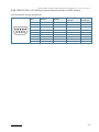
Table 2: Scope of Delivery ............................................................................................................................................................................ 20
Table 3: List of Accessories .......................................................................................................................................................................... 20
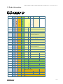
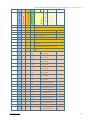
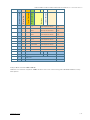
Table 4: Technical Data FlatClient ECO and FlatClient PRO Line ..................................................................................................... 28
Table 5: Technical Data FlatClient ECO and FlatClient PRO Line ...................................................................................................... 28
Table 6: Technical Data FlatClient ECO and FlatClient PRO Line ..................................................................................................... 29
Table 7: Technical Data FlatClient ECO and FlatClient PRO Line ...................................................................................................... 29
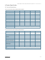
Table 8: Technical Data for FlatClient ECO Line with BayTrail and Braswell processors ....................................................... 30
Table 9: Current Rating at 12 V for FlatClient ECO Line with Intel® Celeron Quad Core J1900 ............................................... 30

FlatClient ECO and FlatClient PRO, FlatClient RCK and FlatClient STS – User Guide Rev. 2.4
www.kontron.com // 13
Table 10: Technical Data FlatClient ECO Line with Intel® Pentium® CPU N4200/Intel® Celeron® J3455 ............................ 31
Table 11: Current Rating at 12 V for FlatClient ECO Line with Intel® Pentium® CPU N4200/Intel® Celeron® J3455......... 31
Table 12: Technical Data FlatClient PRO Line with Haswell and Broadwell processors ......................................................... 32
Table 13: Current Rating at 12 V for FlatClient PRO Line with Intel® Haswell ULT i5-4300U ................................................. 32
Table 14: Technical Data FlatClient PRO Line with Skylake, Whiskey Lake and Kaby Lake CPU ........................................... 33
Table 15: Current Rating at 12 V for FlatClient PRO Line with Intel® Core™ i5-6300U/Core™ i5-7300U/Core™ i5-
8365UE ................................................................................................................................................................................................................ 33
Table 16: Environmental Specification FlatClient ECO and FlatClient PRO Line ......................................................................... 34
Table 17: Compliance ...................................................................................................................................................................................... 35
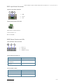
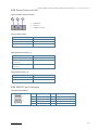
Table 18: Button Functions (1) ..................................................................................................................................................................... 58
Table 19: Power LED (2) ................................................................................................................................................................................. 58
Table 20: Drive Activity (3) ........................................................................................................................................................................... 59
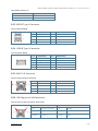
Table 21: Pinout USB 2.0 ................................................................................................................................................................................ 59
Table 22: Pinout USB 2.0 ............................................................................................................................................................................... 59
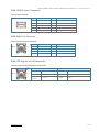
Table 23: Pinout GbE RJ-45 Connector ..................................................................................................................................................... 59
Table 24: Pinout HDMI Connector .............................................................................................................................................................. 60
Table 25: Pinout VGA Connector ................................................................................................................................................................. 60
Table 26: Pinout RS-232/422/485 Connector ....................................................................................................................................... 61
Table 27: Power LED (1) ................................................................................................................................................................................. 63
Table 28: Button Functions (2) ................................................................................................................................................................... 63
Table 29: Drive Activity (3) ........................................................................................................................................................................... 63
Table 30: Pinout USB 2.0 ............................................................................................................................................................................... 63
Table 31: Pinout USB 2.0 ................................................................................................................................................................................ 64
Table 32: Pinout GbE RJ-45 Connector ..................................................................................................................................................... 64
Table 33 : Status of LEDs from GbE RJ-45 Connector ......................................................................................................................... 64
Table 34: Pinout HDMI Connector .............................................................................................................................................................. 65
Table 35: Pinout VGA Connector ................................................................................................................................................................. 65
Table 36: Pinout RS-232/422/485 Connector ...................................................................................................................................... 66
Table 37: Power On Button Functions (1) ................................................................................................................................................ 68
Table 38: Power LED (2) ................................................................................................................................................................................ 68
Table 39: Drive Activity (3) ........................................................................................................................................................................... 68
Table 40: Pinout USB3.0 Connector .......................................................................................................................................................... 68
Table 41: Pinout GbE RJ-45 Connector ..................................................................................................................................................... 69
Table 42: Pinout DisplayPort Connector .................................................................................................................................................. 69
Table 43: Pinout RS-232/422/485 Connector ...................................................................................................................................... 70
Table 44: Power LED (1) ................................................................................................................................................................................ 72
Table 45: Button Functions (2) ................................................................................................................................................................... 72
Table 46: Drive Activity (3) ........................................................................................................................................................................... 72
Table 47: Pinout USB 2.0 ............................................................................................................................................................................... 72
Table 48: Pinout GbE RJ-45 Connector..................................................................................................................................................... 73
Table 49: Pinout DisplayPort Connector.................................................................................................................................................. 73
Table 50: Pinout HDMI Connector .............................................................................................................................................................. 74
List of Figures
Figure 1: FlatClient ECO and PRO, FlatClient STS and FlatClient RCK (right) ................................................................................. 15
Figure 2: Type Label ........................................................................................................................................................................................ 22
Figure 3: Front View Description FlatClient ECO Full-metal ............................................................................................................. 23
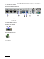
Figure 4: Rear Panel Description – FlatClient ECO (BayTrail) Full-metal variant ...................................................................... 24
Figure 5: Rear Panel Description – FlatClient PRO (Braswell) built-in variant .......................................................................... 24
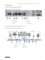
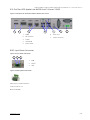
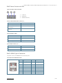
Figure 6: Interfaces for Panel PC FlatClient ECO .................................................................................................................................... 57
Figure 7: Interfaces for Panel PC FlatClient ECO 7" variant................................................................................................................. 57
Figure 8: Input Power Connector................................................................................................................................................................ 58
Figure 9: Mating Power Connector ............................................................................................................................................................ 58
Figure 10: Power-Switch and LEDs ............................................................................................................................................................ 58
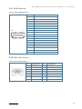
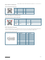
Figure 11: Interfaces for Panel PC FlatClient Apollo Lake variant .................................................................................................... 62

FlatClient ECO and FlatClient PRO, FlatClient RCK and FlatClient STS – User Guide Rev. 2.4
www.kontron.com // 14
Figure 12: Input Power Connector .............................................................................................................................................................. 62
Figure 13: Mating Power Connector .......................................................................................................................................................... 62
Figure 14: Power-Switch and LEDs ............................................................................................................................................................ 63
Figure 15: Interfaces for Panel PC PRO variant ...................................................................................................................................... 67
Figure 16: Input Power Connector .............................................................................................................................................................. 67
Figure 17: Mating Power Connector ........................................................................................................................................................... 67
Figure 18: Power-Switch and LEDs ............................................................................................................................................................ 68
Figure 19: Interfaces for Panel PC FlatClient PRO Skylake/Kaby Lake variant ............................................................................. 71
Figure 20: Input Power Connector .............................................................................................................................................................. 71
Figure 21: Mating Power Connector ........................................................................................................................................................... 71
Figure 22: Power-Switch and LEDs ........................................................................................................................................................... 72
Figure 23: Mating Power Connector .......................................................................................................................................................... 79
Figure 24: Screen with optional RFID function (red circle) ................................................................................................................ 80

FlatClient ECO and FlatClient PRO, FlatClient RCK and FlatClient STS – User Guide Rev. 2.4
www.kontron.com // 15
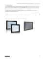
1/ Introduction
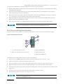
With its FlatClient Monitor series, Kontron offers high mechanical flexibility with respect to the design. It can be used
both as a full-metal solution with VESA 75/75 respectively 100/100 as well as a built-in solution. The front comes
with standard IP65 protection, with the full-metal variant offering a standard IP54. The built-in version is installed
directly on the machine or in a command or control console.
The system is service-friendly for the user and is designed for a long life cycle thanks to carefully selected
components from renowned manufacturers.
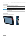
The FlatClient industrial monitor series includes the FlatClient STS stainless steel monitor built-in variant that installs
directly on the machine or in a command or control console. For industrial applications, the FlatClient RCK rack mount
provides easy 19” industrial rack installation.
Figure 1: FlatClient ECO and PRO, FlatClient STS and FlatClient RCK (right)

FlatClient ECO and FlatClient PRO, FlatClient RCK and FlatClient STS – User Guide Rev. 2.4
www.kontron.com // 16
2/ General Safety Instructions
Please read this passage carefully and take careful note of the instructions, which have been compiled for your safety
and to ensure to apply in accordance with intended regulations. If the following general safety instructions are not
observed, it could lead to injuries to the operator and/or damage of the product; in cases of non-observance of the
instructions Kontron Europe is exempt from accident liability, this also applies during the warranty period.
The product has been built and tested according to the basic safety requirements for low voltage (LVD) applications
and has left the manufacturer in safety-related, flawless condition. To maintain this condition and to also ensure safe
operation, the operator must not only observe the correct operating conditions for the product but also the following
general safety instructions:
The product must be used as specified in the product documentation, in which the instructions for safety for the
product and for the operator are described. These contain guidelines for setting up, installation and assembly,
maintenance, transport or storage.
The on-site electrical installation must meet the requirements of the country's specific local regulations.
If a power cable comes with the product, only this cable should be used. Do not use an extension cable to connect
the product.
To guarantee that sufficient air circulation is available to cool the product, please ensure that the ventilation
openings are not covered or blocked. If a filter mat is provided, this should be cleaned regularly. Do not place the
product close to heat sources or damp places. Make sure the product is well ventilated.
Only connect the product to an external power supply providing the voltage type (AC or DC) and the input power
(max. current) specified on the Kontron Product Label and meeting the requirements of the Limited Power Source
(LPS) and Power Source (PS2) of UL/IEC 62368-1 .
Only products or parts that meet the requirements for Power Source (PS1) of UL/IEC 62368-1 may be connected
to the product’s available interfaces (I/O).
Before opening the product, make sure that the product is disconnected from the mains.
Switching off the product by its power button does not disconnect it from the mains. Complete disconnection is
only possible if the power cable is removed from the wall plug or from the product. Ensure that there is free and
easy access to enable disconnection.
The product may only be opened for the insertion or removal of add-on cards (depending on the configuration of
the product). This may only be carried out by qualified operators.
If extensions are being carried out, the following must be observed:
all effective legal regulations and all technical data are adhered to
the power consumption of any add-on card does not exceed the specified limitations
the current consumption of the product does not exceed the value stated on the product label
Only original accessories that have been approved by Kontron Europe can be used.
Please note: safe operation is no longer possible when any of the following applies:
the product has visible damages or
the product is no longer functioning
In this case the product must be switched off and it must be ensured that the product can no longer be
operated.
Handling and operation of the product is permitted only for trained personnel within a work place that is access
controlled.
CAUTION: Risk of explosion if the battery is replaced incorrectly (short-circuited, reverse-poled, wrong battery
type). Dispose of used batteries according to the manufacturer’s instructions.
This product is not suitable for use in locations where children are likely to be present
Additional Safety Instructions for DC Power Supply Circuits
To guarantee safe operation, please observe that:
the external DC power supply must meet the criteria for LPS and PS2 (UL/IEC 62368-1)
no cables or parts without insulation in electrical circuits with dangerous voltage or power should be
touched directly or indirectly
a reliable protective earthing connection is provided

FlatClient ECO and FlatClient PRO, FlatClient RCK and FlatClient STS – User Guide Rev. 2.4
www.kontron.com // 17
a suitable, easily accessible disconnecting device is used in the application (e.g. overcurrent protective
device), if the product itself is not disconnect able
a disconnect device, if provided in or as part of the product, shall disconnect both poles simultaneously
interconnecting power circuits of different products cause no electrical hazards
A sufficient dimensioning of the power cable wires must be selected – according to the maximum electrical
specifications on the product label – as stipulated by EN62368-1 or VDE0100 or EN60204 or UL61010-1
regulations.
For the General Safety Instruction in German or French, visit Kontron’s product web page> Downloads> Manuals>
General Safety Instructions.
2.1. UL Canada: Instructions générales de sécurité
Veuillez lire attentivement ce passage et prendre bonne note des instructions, qui ont été compilées pour votre
sécurité et pour assurer une application conforme aux réglementations prévues. Le non-respect des consignes de
sécurité générales suivantes peut entraîner des blessures pour l'utilisateur et/ou des dommages pour le produit. En
cas de non-respect des consignes, Kontron Europe est exonéré de la responsabilité en cas d'accident, ceci s'applique
également pendant la période de garantie.
Le produit a été construit et testé conformément aux exigences de sécurité de base pour les applications basse
tension (DBT) et a quitté le fabricant dans un état impeccable en matière de sécurité. Pour maintenir cet état et pour
garantir également un fonctionnement sûr, l'opérateur doit non seulement respecter les conditions d'utilisation
correctes du produit, mais aussi les consignes de sécurité générales suivantes :
Le produit doit être utilisé conformément à la documentation du produit, dans laquelle sont décrites les
instructions de sécurité pour le produit et pour l'opérateur. Celles-ci contiennent des directives pour la mise en
place, l'installation et le montage, la maintenance, le transport ou le stockage.
L'installation électrique sur place doit répondre aux exigences des réglementations locales spécifiques du pays.
Si un câble d'alimentation est fourni avec le produit, seul ce câble doit être utilisé. N'utilisez pas de rallonge pour
connecter le produit.
Afin de garantir une circulation d'air suffisante pour refroidir le produit, veuillez vous assurer que les ouvertures
de ventilation ne sont pas couvertes ou obstruées. Si un élément filtrant est fourni, celui-ci doit être nettoyé
régulièrement. Ne placez pas le produit à proximité de sources de chaleur ou d'endroits humides. Veillez à ce que
le produit soit bien ventilé.
Ne connectez le produit qu'à une alimentation externe fournissant le type de tension (AC ou DC) et la puissance
d'entrée (courant max.) spécifiés sur le Label Produit Kontron et répondant aux exigences de la source
d'alimentation limitée (LPS) et de la source d'alimentation (PS2) de la norme UL/IEC 62368-1 .
Seuls les produits ou les pièces qui répondent aux exigences de la source d'alimentation (PS1) de la norme UL/IEC
62368-1 peuvent être connectés aux interfaces (E/S) disponibles du produit.
Avant d'ouvrir le produit, assurez-vous qu'il est bien débranché du secteur.
Le fait d'éteindre le produit par son bouton de mise en marche ne le déconnecte pas du secteur. Une déconnexion
complète n'est possible que si le câble d'alimentation est retiré de la prise murale ou du produit. Veillez à ce que
l'accès soit libre et facile pour permettre la déconnexion.
Le produit ne peut être ouvert que pour l'insertion ou le retrait de cartes supplémentaires (selon la configuration
du produit). Cette opération ne peut être effectuée que par des opérateurs qualifiés.
Si des extensions sont effectuées, les points suivants doivent être respectés :
toutes les réglementations légales en vigueur et toutes les données techniques sont respectées
la consommation électrique d'une carte supplémentaire ne dépasse pas les limites spécifiées
la consommation actuelle du produit ne dépasse pas la valeur indiquée sur l'étiquette du produit.
Seuls les accessoires d'origine approuvés par Kontron Europe peuvent être utilisés.
Veuillez noter que la sécurité des opérations n'est plus possible lorsque l'une des conditions suivantes
s'applique.
le produit présente des dommages visibles ou

FlatClient ECO and FlatClient PRO, FlatClient RCK and FlatClient STS – User Guide Rev. 2.4
www.kontron.com // 18
le produit ne fonctionne plus. Dans ce cas, le produit doit être éteint et il faut s'assurer que le produit ne
puisse plus être utilisé.
La manipulation et le fonctionnement du produit ne sont autorisés que pour le personnel formé dans un lieu de
travail dont l'accès est contrôlé.
ATTENTION: Risque d'explosion si la batterie est remplacée de manière incorrecte (court-circuit, inversion de
polarité, mauvais type de batterie). Éliminez les piles usagées conformément aux instructions du fabricant.
Ce produit n'est pas adapté à une utilisation dans des endroits où des enfants sont susceptibles d'être présents
Instructions de sécurité supplémentaires pour les circuits d'alimentation en courant continu
Pour garantir un fonctionnement sûr, veuillez observer ce qui suit:
l'alimentation électrique externe en courant continu doit répondre aux critères des LPS et PS2 (UL/IEC
62368-1)
aucun câble ou pièce non isolée dans les circuits électriques ayant une tension ou une puissance dangereuse
ne doit être touché directement ou indirectement
une connexion fiable à la terre de protection est fournie
un dispositif de déconnexion approprié et facilement accessible est utilisé dans l'application (par exemple,
un dispositif de protection contre les surintensités), si le produit lui-même n'est pas en mesure d'être
déconnecté.
un dispositif de déconnexion, s'il est prévu dans le produit ou s'il en fait partie, doit déconnecter les deux
pôles simultanément
l'interconnexion des circuits électriques de différents produits ne présente aucun risque électrique
Un dimensionnement suffisant des fils du câble d'alimentation doit être choisi - en fonction des spécifications
électriques maximales figurant sur l'étiquette du produit - comme stipulé par les réglementations EN62368-1 ou
VDE0100 ou EN60204 ou UL61010-1.
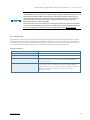
2.2. Electromagnetic Compatibility EU
This product is in conformity with the protection requirements of EU Council Directive 2004/108/EC on the
approximation of the laws of the Member States relating to electromagnetic compatibility. If the user modifies and/or
adds to the equipment (e.g. installation of add-on cards) the prerequisites for the CE conformity declaration, (safety
requirements) may no longer apply.
Table 1: Electromagnetic Compatibility CE
EN 55032:2015 Information technology equipment, Radio disturbance characteristics,
Limits and methods of measurement (CISPR 32:2015)
EN 61000-6-2:2005 + Cor.:2005 Electromagnetic compatibility (EMC), Part 6-2:Generic Standards -
Immunity for industrial environments+ CENELEC- Cor.:2005

FlatClient ECO and FlatClient PRO, FlatClient RCK and FlatClient STS – User Guide Rev. 2.4
www.kontron.com // 19
2.3. Electrostatic Discharge (ESD)
A sudden discharge of electrostatic electricity can destroy static-sensitive devices or micro-circuitry. Therefore,
proper packaging and grounding techniques are necessary precautions to prevent damage.
Always take the following precautions:
ESD Sensitive Device!
Keep electrostatic sensitive parts in their containers until they arrive at the ESD-safe
workplace.
Always be properly grounded when touching a sensitive board, component, or
assembly.
For more Information, see the Special Handling and Unpacking Instruction within this user guide and Chapter 2.3.1:
Grounding Methods below.
2.3.1. Grounding Methods
The following measures help to avoid electrostatic damages to the device:
Cover workstations with approved antistatic material. Always wear a wrist strap connected to the workplace, as
well as properly grounded tools and equipment.
Use antistatic mats, heel straps, or air ionizers for more protection.
Always handle electrostatically sensitive components by their edge or by their casing.
Avoid contact with pins, leads, or circuitry.
Turn off power and input signals before inserting and removing connectors or connecting test equipment.
Keep the work area free of non-conductive materials such as ordinary plastic assembly aids and styrofoam.
Use field service tools such as cutters, screwdrivers, and vacuum cleaners that are conductive.
Always place drives and boards with the PCB-assembly-side down on the foam.
2.4. Instructions for Lithium Battery
If the product is equipped with a lithium battery. When replacing the battery observe the instructions below.
Risk of Explosion if Battery is replaced by an incorrect Type. Dispose of used batteries
According to the instructions.
Risque d’explosion si la batterie est remplacée par un type incorrect. Mettre au rebus les
batteries usagées selon les instructions.
Do not dispose of lithium batteries in general trash collection. Dispose of the battery
according to the local regulations dealing with the disposal of these special materials, (e.g.
to the collecting points for dispose of batteries).

FlatClient ECO and FlatClient PRO, FlatClient RCK and FlatClient STS – User Guide Rev. 2.4
www.kontron.com // 20
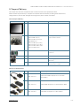
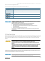
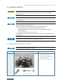
3/ Scope of Delivery
This chapter describes the components that are delivered and can be optionally ordered.
Please check that your delivery is complete and contains the items below (according to the ordered unit
configuration). If you discover damaged or missing items, please contact your dealer.
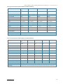
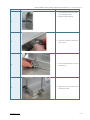
Table 2: Scope of Delivery
Qty Part Number Part Description
1 s. order information chapter 5/ FlatClient ECO or PRO Monitor
1 EM21-100189-01 (7.0")
EM21-100168-01 (10.1")
EM21-100065-0 (10.4"/12.1")
1064-9094 (13.3")
EM21-100066-0 (15.0"/15.6")
EM21-100067-01 (17.0"/19.0")
EM21-100068-01 (18.5"/23.8")
EM21-100069-01 (21.5")
Mounting set with clamps and screws,
only for built-in variant
1 EE04-100001-01 Phoenix 3 pin Power Subcon in D-sub 9
connector.
1 840-0059 EU-Power cord 1,8m
1 ER40-100001-01
Power Supply Set 24 VDC /w Phoenix
Connector
1 ER40-100005-01 Power supply Set 24 VDC /w Phoenix
incl. EU-Power cord 1,8m
Table 3: List of Accessories
Qty Part Number Part Description
1 PR22-100004-01 Adapter Kabel HDMI - DisplayPort, 20cm, 4K aktiv,
Delock: 62607
1 PR22-100005-01 Adapter HDMI - DisplayPort 1.2, 4K aktiv, Delock: 65573
1 PR22-100006-01 Adapter DVI-D - DisplayPort 1.1, Delock: 65257
La page charge ...
La page charge ...
La page charge ...
La page charge ...
La page charge ...
La page charge ...
La page charge ...
La page charge ...
La page charge ...
La page charge ...
La page charge ...
La page charge ...
La page charge ...
La page charge ...
La page charge ...
La page charge ...
La page charge ...
La page charge ...
La page charge ...
La page charge ...
La page charge ...
La page charge ...
La page charge ...
La page charge ...
La page charge ...
La page charge ...
La page charge ...
La page charge ...
La page charge ...
La page charge ...
La page charge ...
La page charge ...
La page charge ...
La page charge ...
La page charge ...
La page charge ...
La page charge ...
La page charge ...
La page charge ...
La page charge ...
La page charge ...
La page charge ...
La page charge ...
La page charge ...
La page charge ...
La page charge ...
La page charge ...
La page charge ...
La page charge ...
La page charge ...
La page charge ...
La page charge ...
La page charge ...
La page charge ...
La page charge ...
La page charge ...
La page charge ...
La page charge ...
La page charge ...
La page charge ...
La page charge ...
La page charge ...
La page charge ...
La page charge ...
La page charge ...
-
 1
1
-
 2
2
-
 3
3
-
 4
4
-
 5
5
-
 6
6
-
 7
7
-
 8
8
-
 9
9
-
 10
10
-
 11
11
-
 12
12
-
 13
13
-
 14
14
-
 15
15
-
 16
16
-
 17
17
-
 18
18
-
 19
19
-
 20
20
-
 21
21
-
 22
22
-
 23
23
-
 24
24
-
 25
25
-
 26
26
-
 27
27
-
 28
28
-
 29
29
-
 30
30
-
 31
31
-
 32
32
-
 33
33
-
 34
34
-
 35
35
-
 36
36
-
 37
37
-
 38
38
-
 39
39
-
 40
40
-
 41
41
-
 42
42
-
 43
43
-
 44
44
-
 45
45
-
 46
46
-
 47
47
-
 48
48
-
 49
49
-
 50
50
-
 51
51
-
 52
52
-
 53
53
-
 54
54
-
 55
55
-
 56
56
-
 57
57
-
 58
58
-
 59
59
-
 60
60
-
 61
61
-
 62
62
-
 63
63
-
 64
64
-
 65
65
-
 66
66
-
 67
67
-
 68
68
-
 69
69
-
 70
70
-
 71
71
-
 72
72
-
 73
73
-
 74
74
-
 75
75
-
 76
76
-
 77
77
-
 78
78
-
 79
79
-
 80
80
-
 81
81
-
 82
82
-
 83
83
-
 84
84
-
 85
85


kontron FlatClient STS Le manuel du propriétaire
- Taper
- Le manuel du propriétaire
- Ce manuel convient également à
dans d''autres langues
Documents connexes
Autres documents
-
Sharp PN-CD701 Manuel utilisateur
-
Mircom LT-6664 Mode d'emploi
-
-
-
HUMANTECHNIK PR22 Manuel utilisateur
-
 MicroTouch IC-100P-AA1 Manuel utilisateur
-
Eurotech DynaGATE 10-12 Le manuel du propriétaire
-
Eurotech ReliaGATE 10-12 Le manuel du propriétaire
-
-
