La page est en cours de chargement...

IC-100P-AA1
Interactive Computer
User Manual

1
About This Document
No part of this publication may be reproduced, transmitted, transcribed, stored in a
retrieval system, or translated into any language or computer language, in any form or
by any means, including, but not limited to, electronic, magnetic, optical, chemical,
manual, or otherwise without prior written permission of MicroTouchTM a TES Company.
The information in this document is subject to change without notice. MicroTouchTM a
TES Company makes no representations or warranties with respect to the contents
herein, and specifically disclaims any implied warranties of merchantability or fitness for
a particular purpose. MicroTouchTM a TES Company reserves the right to revise this
publication and to make changes from time to time in the content hereof without
obligation of MicroTouchTM a TES Company to notify any person of such revisions or
changes. Windows is a registered trademark of Microsoft, Inc. Other brand or product
names are trademarks of their respective holders.

2 |
Compliance Information
For FCC (USA)
This equipment has been tested and fund to comply with the limits for a Class A digital
device, pursuant to part 15 of the FCC Rules. There limits are designed to provide
reasonable protection against harmful interference when the equipment is operated in a
commercial environment. This equipment generates, uses, and can radiate radio
frequency energy and, if not installed and used in accordance with the instruction manual,
may cause harmful interference to radio communications. Operation of this equipment in a
residential area is likely to cause harmful interference in which case the user will be
required to correct the interference at his own expense.
This device complies with part 15 of the FCC Rules. Operation is subject to the following
two conditions: (1) this device may not cause harmful interference, and (2) this device
must accept any interference received, including interference that may cause undesired
operation.
For IC (Canada)
CAN ICES-3(A)/NMB-3(A)
For CE (EU)
The device complies with the EMC Directive 2014/30/EU and Low Voltage Directive
2014/35/EU

3 |
Renseignements relatifs à la conformité
Pour la FCC (États-Unis).
Ce matériel a fait l’objet d’essais qui ont déterminé qu’il respectait les limites d’un appareil
de classe A selon la partie 15 des règlements de la FCC. Ces limites sont établies pour
assurer une protection raisonnable contre les parasites nuisant à un fonctionnement dans
un environnement commercial. Ce matériel génère, utilise et peut émettre des ondes radio
électriques, et lorsqu’il n’est pas installé et utilisé selon le manuel d’instructions, peut
causer des parasites nuisant aux communications radio. L’utilisation de ce matériel dans
une zone résidentielle est susceptible de causer des parasites auquel cas l’utilisateur est
tenu de corriger le problème des parasites à ses propres frais.
L’appareil respecte la partie 15 des règlements de la FCC. Le fonctionnement doit
respecter les deux conditions suivantes : 1) cet appareil ne doit pas causer de parasites et
(2) cet appareil doit accepter tous les parasites reçus, notamment ceux pouvant causer un
fonctionnement non voulu.
Pour Industrie Canada
Norme canadienne NMB-3(A)
Pour la CE (UE)
L’appareil respecte la directive 2014/30/UE relative à la compatibilité électromagnétique et
la directive 2014/35/EU sur les limites de basse tension

4 |
Usage Notice
Precautions
Please follow all warnings, precautions and maintenance as recommended in this user’s
manual to maximize the life of your unit.
Do
:
▪ Turn off the product before cleaning.
▪ Use a soft cloth moistened with mild detergent to clean the product housing.
▪ Use only the qualified power adapter that comes with your device.
▪ Disconnect the power plug from AC outlet if the product is not going to be used for an
extended period of time.
Don’t
:
▪ Do not use abrasive cleaners, waxes or solvents for your cleaning.
▪ Do not operate the product under the following conditions:
- Extremely hot, cold or humid environment.
- Areas susceptible to excessive dust and dirt.
- Near any appliance generating a strong magnetic field.
Caution
Risk of explosion if battery is replaced by an incorrect type. Dispose of used batteries
according to the instructions.
! Warning - To prevent the risk of fire or shock hazards, and do not
expose the product to moisture.
! Warning - Please do not open or disassemble the product as this may
cause electric shock.
! Warning - Power cord shall be connected to a socket-outlet with
earthing connection.
! Warning - Stability Hazard. The touch monitor may fall, causing
serious personal injury or death. To prevent injury, this
touch monitor must be securely attached to the wall in
accordance with the installation instructions.

5 |
Avis d’utilisation
Précautions
Veuillez suivre toutes les mises en garde, précautions et entretiens recommandés dans
ce manuel d’utilisation pour maximiser la durée de vie de votre unité.
À faire :
▪ Éteindre l’appareil avant de le nettoyer.
▪ Utiliser un chiffon humidifié par une solution savonneuse pour nettoyer le boîtier du
produit.
▪ Utiliser uniquement l’adaptateur d’alimentation prescrit pour votre appareil.
▪ Débrancher l’appareil lorsqu’il n’est pas utilisé pendant une période prolongée.
À éviter :
▪ Ne pas utiliser de nettoyants abrasifs, de cires ou de solvants pour le nettoyage
▪ Ne jamais utiliser l’appareil dans les conditions suivantes :
– des conditions environnementales extrêmes (chaud, froid ou humidité)
– des endroits remplis de poussières et de saletés.
– à proximité d’appareils produisant un fort champ magnétique.
Mise en garde
Risque d'explosion si la batterie est remplacée par un type incorrect. Jetez les piles
usagées conformément aux instructions.
! Mise en garde — Pour prévenir les risques d’incendie ou
d’électrocution, ne pas exposer le produit à l’humidité.
! Mise en garde — Prière de ne pas ouvrir ou démonter le produit, car
cela pourrait entraîner l’électrocution.
! Mise en garde – Le cordon d’alimentation doit être branché à une
prise pourvue d’une mise à la terre.
! Mise en garde — Risque de renversement. Le moniteur tactile peut se
renverser et causer de graves blessures corporelles, voire la mort.
Pour prévenir les blessures, ce moniteur tactile doit être solidement
fixé au mur selon les instructions d’installation.

6 |
Table of Contents
Chapter 1 ........................................................................................................................ 8
1.1 Overview .................................................................................................................... 9
1.2 Feature ....................................................................................................................... 9
1.3 Specifications ............................................................................................................. 9
1.4 Block Diagram .......................................................................................................... 11
1.5 Interface Connectors ................................................................................................ 12
1.6 Package Overview ................................................................................................... 14
Chapter 2 ...................................................................................................................... 16
2.1 About VESA Mount .................................................................................................. 17
2.2 About Wall Mount ..................................................................................................... 19
2.2.1 Wall Mount A .................................................................................................... 19
2.2.2 Wall Mount B .................................................................................................... 21
2.2.3 Wall Mount C .................................................................................................... 24
2.3 Power On / Off Switch .............................................................................................. 27
2.4 Light Bar .................................................................................................................. 28
2.5 NFC ......................................................................................................................... 29
2.6 Dimension ................................................................................................................ 30
2.7 Optional Accessory Installation ................................................................................ 31
2.7.1 Install the Adjustable Cable Hanging Kit .......................................................... 31
Chapter 3 ...................................................................................................................... 38
3.1 Initial Turn-On .......................................................................................................... 39
3.2 Boot Touch Panel PC .............................................................................................. 39
Chapter 4 ...................................................................................................................... 41
4.1 App Main Interface ................................................................................................... 41
Chapter 5 ...................................................................................................................... 43
5.1 Operating Instructions .............................................................................................. 43
5.1.1 Equipment Operation (no identification card required) ..................................... 44
5.1.2 NTAG Card Operation (other card types are not supported) ............................ 45
5.1.3 Mifare Card Operation (other card types are not supported) ............................ 46
5.2 Project API Description ............................................................................................ 48
5.2.1 Equipment Related Operations ........................................................................ 48
5.2.2 NTAG Card Operation ...................................................................................... 48
5.2.3 Mifare Card Operation ...................................................................................... 49
Appendix ...................................................................................................................... 50


8 |
Chapter 1
Product Introduction

9 |
1.1 Overview
The IC-100P-AA1 series is a thinner 10.1” touch panel pc that offers a unique screw less
design with expandability and flexibility, making expansion and accessory installation
much easier. The versatility of IC-100P-AA1 series is an exceptional choice for
applications in all business sectors, especially in the retail market.
1.2 Feature
▪ Support Rockchip RK3288 processor.
▪ Unique screw less design for better user experience.
▪ Patented I/O design for better wiring management while implementation.
1.3 Specifications
System
CPU
Rockchip RK3288, Quad-core Cortex-A17 up to 1.8GHz
GPU
Mail-T760 MP4
DDR
2GB dual channel DDRIII
Storage
16GB eMMC
Input Power
DC in 12V/2A 2PIN (first); POE 48V/55V (second)
(Can’t be switched after system stand-by power on)
Display
Single channel LVDS, resolution up to 1280x800P60
Touch
10.1-inch P-Cap touch sensor (EETI 80H46 controller),
supports 10 fingers touch function.
Audio
1 x speaker (2W x 1)
Camera
FHD (1920x1080), 1/6inch sensor
D-FOV 77.5゜; H-FOV 69.7゜; V-FOV 42.8e゜±5%
NFC
ISO/IEC 14443A
Support S50/S70/desfire/N-Tag/ultralight/CPU card
13.56MHz, 125KHz
Effective distance: 0~10mm
Light Bar
RGB Color Mixing
Network
Gigabit Ethernet

10 |
Wi-Fi 802.11a/b/g/n 1T1R
Bluetooth 4.0 (Support BLE)
External IO Ports
1 x TF slot (Support SDHC 2.0)
1 x LAN (Support 10/100/1000Mbps, POE (802.3at 25W))
1 x HDMI Type-C (Support 4K@60Hz)
1 x USB2.0 Type-A
1 x USB2.0 Type-C OTG (5V/0.5A)
OS Version
Android 8.1
Operation Temp.
0°C ~40°C
Storage Temp.
-20C to 60C
Operation Humidity
20~80%
Storage Humidity
10~90%
LCD Touch Panel
WT1010C13-V01
Size
10.1” TFT LCD
Brightness
(non-touch screen)
Typical 450cd/m2; min. 400 cd/m2
Brightness
(P-CAP)
Typical 382 cd/m2; min. 340 cd/m2
Number of Pixels
1280 (H) × 800 (V)/ 60Hz
IVO M101NWWB R3
Size
10.1” TFT LCD
Brightness
(non-touch screen)
Typical 350cd/m2; min. 300 cd/m2
Brightness
(P-CAP)
Typical 300 cd/m2; min. 255 cd/m2
Number of Pixels
1280 (H) × 800 (V)/ 60Hz
Environment
Certificate
CE、FCC、LVD
Mounting
VESA 75 mm x 75 mm
Dimension (W x H x D)
247.4 mm x 170.5 mm x 25.7 mm
Net Weight
0.94 Kg
Gross Weight
1.34 Kg

11 |
1.4 Block Diagram

12 |
1.5 Interface Connectors
12V DC in
Pin #
Signal Name
Pin #
Signal Name
1
12V
2
GND
RJ45 for LAN
Pin #
Signal Name
Pin #
Signal Name
1
TP1+
2
TP1-
3
TP2+
4
TP3-
5
TP3+
6
TP2-
7
TP4+
8
TP4-
LED
Function
Color
Left
Active
Yellow (Blink)
Right
10M/100M/1000M
Green
USB2.0
Pin #
Signal Name
Pin #
Signal Name
1
USB5V
2
D-
3
D+
4
GND

13 |
USB-C
Pin #
Signal Name
Pin #
Signal Name
A1
GND
B12
GND
A2
B11
A3
B10
A4
VBUS
B9
VBUS
A5
B8
A6
Dp1
B7
Dn2
A7
Dn1
B6
Dp2
A8
B5
A9
VBUS
B4
VBUS
A10
B3
A11
B2
A12
GND
B1
GND
HDMI-C
Pin #
Signal Name
Pin #
Signal Name
1
TMDS Data2 Shield
2
TMDS Data2+
3
TMDS Data2-
4
TMDS Data1 Shield
5
TMDS Data1+
6
TMDS Data1-
7
TMDS Data0 Shield
8
TMDS Data0+
9
TMDS Data0-
10
TMDS Clock Shield
11
TMDS Clock+
12
TMDS Clock-
13
DDC/CEC Ground
14
CEC
(N.C on device)
15
SCL
16
SDA
17
Reserved
(N.C. on device)
18
+5V Power
19
Hot Plug Detect
TF card
Pin #
Signal Name
Pin #
Signal Name
1
DAT2
2
DAT3
3
CMD
4
VCC
5
CLK
6
GND
7
DAT0
8
DAT1
9
CD

14 |
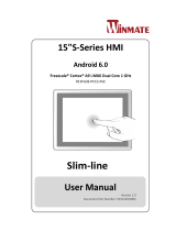
1.6 Package Overview
Touch Panel PC
DC Power Supply
Screw
Wall Mount Kit
Cable Tie
Adjustable Cable Hanging
Kit A (Optional)
Adjustable Cable Hanging
Kit B (Optional)
! Warming!
This product is intended to be supplied by a UL Listed Power Adapter, rated
12Vdc, 2A maximum. (complied with LPS or PS2) T-ambient = 40 degree C
minimum, and the altitude of operation = 3048m minimum. If it needs further
assistance with purchasing the power source, please contact to MicroTouch for
further information.

15 |
! Mise en garde!
Cet appareil est conçu avec une alimentation de courant CA, d’une tension
nominale de 12Vdc, 2A maximum. (conforme au LPS ou PS2) T-ambient = 40
degrés C minimum et l’altitude de l’utilisation = 3048m minimum. Pour d’autres
conseils pour l’installation de la source d’alimentation, communiquer avec
MicroTouch pour de plus amples renseignements.

16 |
Chapter 2
Product Installation

17 |
2.1 About VESA Mount
The IC-100P-AA1 series conform to the “VESA Flat Display Mounting Interface
Standard” which defines a physical mounting interface for touch panel pc, and
corresponding with the standards of touch panel pc mounting devices, such as
wall-mounted or pole-mounted. The VESA mount is located on the back of this unit.
VESA
Mount
! Warming!
Please select the MicroTouch original screws!
The distance between the back cover surface and the bottom of the screw hole
is 5 mm (without wall mount kit). Please use four M4 / 5 mm screws diameter
with proper length to mount your monitor.
Note: The mounting stand must be able to support at least 2.2 lbs (1 Kg).
! Warming!
The equipment is only suitable for mounting ceiling or wall at hights ≤ 2m.

18 |
! Mise en garde!
Sélectionner les vis d’origine de MicroTouch!
La distance entre la surface du couvercle arrière et le bas de l’orifice de la vis
est de 5 mm (sans kit de montage mural). Utiliser quatre vis M4 de 5 mm de
diamètre pour le montage de votre moniteur.
Remarque : Le support de montage doit pouvoir supporter un poids d’au moins
2,2 lb (1 kg).
! Mise en garde!
L'équipement ne convient que pour le montage au plafond ou au mur à des
hauteurs ≤ 2 m.

19 |
2.2 About Wall Mount
The IC-100P-AA1 series support wall mount and this touch panel pc can be mounted
to the wooden, glass or concrete wall.
Note: Please install/ dismantle the product when the computer system is in the
shutdown state.
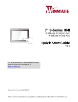
2.2.1 Wall Mount A
Step 1: Install the four screws (not supplied) to fasten the wall mount kit.
Note: Please use the appropriate type of screws for your wall type.
Step 2: Connect the Ethernet cable and power cable to touch panel pc.
Step 3: Route cables.
Wooden or concrete wall
Step 2
Step 3
/