Keysight Technologies N5752A Manuel utilisateur
- Catégorie
- Blocs d'alimentation
- Taper
- Manuel utilisateur

User’s Guide
Keysight Series N5700
System DC Power
Supply


Series N5700 User’s Guide 3
Legal Notices
© Keysight Technologies 2004 - 2021
No part of this document may be
photocopied, reproduced, or translated
to another language without the prior
agreement and written consent of
Keysight Technologies as governed by
United States and international
copyright laws.
Warranty
The material contained in this
document is provided “as is,” and is
subject to being changed, without
notice, in future editions. Further, to
the maximum extent permitted by
applicable law, Keysight disclaims all
warranties, either express or implied,
with regard to this manual and any
information contained herein,
including but not limited to the
implied warranties of merchantability
and fitness for a particular purpose.
Keysight shall not be liable for errors
or for incidental or consequential
damages in connection with the
furnishing, use, or performance of this
document or of any information
contained herein. Should Keysight
and the user have a separate written
agreement with warranty terms
covering the material in this
document that conflict with these
terms, the warranty terms in the
separate agreement shall control.
Manual Editions
Manual Part Number: 5969-2917
Edition 9, December 2021.
Reprints of this manual containing
minor corrections and updates may
have the same printing date. Revised
editions are identified by a new
printing date.
Declaration of Conformity
Declarations of Conformity for this
product and for other Keysight
products may be downloaded from
the Web. Go to
http://www.keysight.com/go/conform
ity and click on “Declarations of
Conformity.” You can then search by
product number to find the latest
Declaration of Conformity.
Waste Electrical and
Electronic Equipment (WEEE)
Directive 2002/96/EC
This product complies with the WEEE
Directive 2002/96/EC) marketing
requirement. The affixed product label
(see below) indicates that you must
not discard this electrical/electronic
product in domestic household waste.
Product Category: With reference to
the equipment types in the WEEE
directive Annex 1, this product is
classified as “Monitoring and Control
instrumentation” product.
Do not dispose in domestic household
waste.
To return unwanted products, contact
our local Keysight office, or see
http://about.keysight.com/en/compa
nyinfo/environment/takeback.shtml
for more information.
Certification
Keysight Technologies certifies that
this product met its published
specifications at time of shipment
from the factory. Keysight
Technologies further certifies that its
calibration measurements are
traceable to the United States
National Institute of Standards and
Technology, to the extent allowed by
the Institute's calibration facility, and
to the calibration facilities of other
International Standards Organization
members.
Exclusive Remedies
THE REMEDIES PROVIDED HEREIN
ARE THE CUSTOMER'S SOLE AND
EXCLUSIVE REMEDIES. KEYSIGHT
TECHNOLOGIES SHALL NOT BE
LIABLE FOR ANY DIRECT, INDIRECT,
SPECIAL, INCIDENTAL, OR
CONSEQUENTIAL DAMAGES,
WHETHER BASED ON CONTRACT,
TORT, OR ANY OTHER LEGAL
THEORY.
Assistance
This product comes with the standard
product warranty. Warranty options,
extended support contacts, product
maintenance agreements and
customer assistance agreements are
also available. Contact your nearest
Keysight Technologies Sales and
Service office for further information
on Keysight Technologies' full line of
Support Programs.
Technologies Licenses
The hardware and or software
described in this document are
furnished under a license and may be
used or copied only in accordance
with the terms of such license.
Restricted Rights Legend
Software and technical data rights
granted to the federal government
include only those rights customarily
provided to end user customers.
Keysight provides this customary
commercial license in Software and
technical data pursuant to FAR
12.211 (Technical Data) and 12.212
(Computer Software) and, for the
Department of Defense, DFARS
252.227-7015 (Technical Data –
Commercial Items) and DFARS
227.7202-3 (Rights in Commercial
Computer Software or Computer
Software Documentation).
Trademarks
Microsoft and Windows are U.S.
registered trademarks of Microsoft
Corporation.

4 Series N5700 User’s Guide
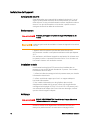
Safety Notices
The following general safety
precautions must be observed during
all phases of operation of this
instrument. Failure to comply with
these precautions or with specific
warnings or instructions elsewhere in
this manual violates safety standards
of design, manufacture, and intended
use of the instrument. Keysight
Technologies assumes no liability for
the customer's failure to comply with
these requirements.
General
Do not use this product in any
manner not specified by the
manufacturer. The protective features
of this product may be impaired if it is
used in a manner not specified in the
operation instructions.
Before Applying Power
Verify that all safety precautions are
taken. Make all connections to the
unit before applying power. Note the
instrument's external markings
described under "Safety Symbols"
Ground the Instrument
This product is a Safety Class 1
instrument (provided with a protective
earth terminal). To minimize shock
hazard, the instrument chassis and
cover must be connected to an
electrical ground. The instrument
must be connected to the ac power
mains through a grounded power
cable, with the ground wire firmly
connected to an electrical ground
(safety ground) at the power outlet.
Any interruption of the protective
(grounding) conductor or
disconnection of the protective earth
terminal will cause a potential shock
hazard that could result in personal
injury.
Fuses
The instrument contains an internal
fuse, which is not customer
accessible.
Do Not Operate in an Explosive
Atmosphere
Do not operate the instrument in the
presence of flammable gases or
fumes.
Do Not Remove the Instrument
Cover
Only qualified, service-trained
personnel who are aware of the
hazards involved should remove
instrument covers. Always disconnect
the power cable and any external
circuits before removing the
instrument cover.
Do Not Modify the Instrument
Do not install substitute parts or
perform any unauthorized
modification to the product. Return
the product to a Keysight Sales and
Service Office for service and repair to
ensure that safety features are
maintained.
In Case of Damage
Instruments that appear damaged or
defective should be made inoperative
and secured against unintended
operation until they can be repaired
by qualified service personnel
A CAUTION notice denotes a
hazard. It calls attention to an
operating procedure, practice, or
the like that, if not correctly
performed or adhered to, could
result in damage to the product or
loss of important data. Do not
proceed beyond a CAUTION
notice until the indicated
conditions are fully understood
and met.
A WARNING notice denotes a
hazard. It calls attention to an
operating procedure, practice, or
the like that, if not correctly
performed or adhered to, could
result in personal injury or death.
Do not proceed beyond a
WARNING notice until the
indicated conditions are fully
understood and met.
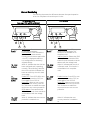
Safety Symbols
Direct current
Alternating current
Both direct and
alternating
current
Three phase alternating
current
Earth (ground) terminal
Protective earth ground
terminal.
Frame or chassis
terminal
Terminal is at earth
potential.
Neutral conductor on
per
manently installed
equipment
Line conductor on
permanently installed
equipment.
On supply
Off supply
Standby supply. Unit is not
completely disconnected
from ac mains when
switch is off
In position of a bi-stable
push switch
Out position of a bi-stable
push switch
Caution, risk of electric
shock
Caution, hot surface
Caution, refer to
accompanying
documents
CAUTION
WARNING

Series N5700 User’s Guide 5
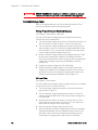
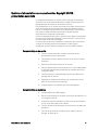
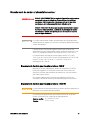
In this Book
This User’s Manual contains the operating instructions, installation
instructions, and specifications of the Keysight Technologies Series
N5700 750W and 1500W System DC Power Supplies. Specific chapters
in this manual contain the following information:
Quick Reference – Chapter 1 is a quick reference section that helps
you quickly become familiar with your Keysight N5700 power supply.
Installation – Chapter 2 describes how to install your power supply.
It describes how to connect various loads to the output. It discusses
remote sensing as well as parallel and series operation.
Operating the Power Supply Locally – Chapter 3 describes how to
operate the power supply from the front panel and from the analog
connector on the rear panel. It also includes a turn-on check-out
procedure to verify the unit is operating properly.
Operating the Power Supply Remotely – Chapter 4 describes how to
configure the remote interfaces. It also gives a brief overview of the
SCPI command structure and basic programming concepts.
Language Reference – Chapter 5 describes all of the SCPI
programming commands.
Programming Examples – Chapter 6 provides Visual BASIC example
programs that illustrate some common applications.
Specifications – Appendix A describes specifications and
supplemental characteristics.
Verification and Calibration Procedures – Appendix B explains the
verification and calibration procedures.
Service – Appendix C describes what to do if your unit requires
service.
Compatibility – Appendix D documents the compatibility commands
of the Keysight 603xA power supplies that are supported by the
Keysight N5700 power supplies.
NOTE
You can contact Keysight
Technologies at one of the following telephone
numbers for warranty, service, or technical support information.
In the United States: (800) 829-4444
In Europe: 31 20 547 2111
In Japan: 0120-421-345
Or use our Web link for information on contacting Keysight in your
country or specific location: http://www.keysight.com/find/assist
Or contact your Keysight Technologies Representative.
The web contains the most up to date version of the manual. Go to
http://www.keysight.com/find/N5700 to get the latest version of the
manual.

6 Series N5700 User’s Guide
Contents
1 Quick Reference ............................................................................................................ 9
The Keysight N5700 DC Power Supplies – At a Glance ............... 10
The Front Panel - At a Glance ....................................................... 12
The Rear Panel – At a Glance ........................................................ 14
2 Installation ................................................................................................................... 17
General Information ....................................................................... 18
Inspecting the Unit ......................................................................... 19
Installing the Unit ........................................................................... 19
Connecting the Line Cord .............................................................. 21
Connecting the Load ...................................................................... 23
Output Voltage Sensing ................................................................. 26
Load Considerations ....................................................................... 28
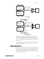
Parallel Connections ...................................................................... 30
Series Connections ......................................................................... 32
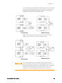
J1 Connector Connections ............................................................ 34
3 Operating the Power Supply Locally ........................................................................... 35
Turn-On Check-Out ....................................................................... 36
Normal Operation ........................................................................... 38
Protection Functions ...................................................................... 39
Output On/Off Controls .................................................................. 42
Analog Programming of Output Voltage and Current .................. 44
4 Operating the Power Supply Remotely ....................................................................... 49
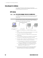
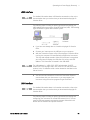
Connecting to the Interfaces ......................................................... 50
SCPI Commands – an Introduction ............................................... 59
5 Language Reference ................................................................................................... 65
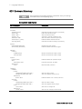
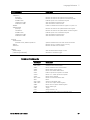
SCPI Command Summary ............................................................. 66
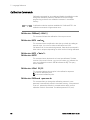
Calibration Commands................................................................... 68
Measure Commands ...................................................................... 69
Output Commands ......................................................................... 70
Source Commands ......................................................................... 71
Status Commands .......................................................................... 73
System Commands ........................................................................ 79
Trigger Commands ......................................................................... 81

Series N5700 User’s Guide 7
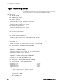
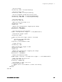
6 Programming Examples .............................................................................................. 83
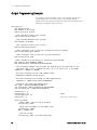
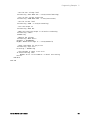
Output Programming Example ...................................................... 84
Trigger Programming Example ...................................................... 86
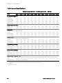
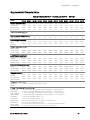
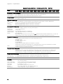
A Specifications .............................................................................................................. 89
Performance Specifications ........................................................... 90
Supplemental Characteristics ........................................................ 91
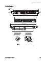
Outline Diagram ............................................................................. 93
B Verification and Calibration ........................................................................................ 95
Verification ...................................................................................... 96
Calibration .................................................................................... 115
C Service ...................................................................................................................... 117
Types of Service Available ............................................................ 118
Repackaging for Shipment .......................................................... 118
Operating Checklist ...................................................................... 118
Error Messages ............................................................................. 120
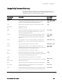
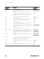
D Compatibility ............................................................................................................. 125
Differences – In General ............................................................... 126
Compatibility Command Summary .............................................. 127
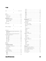
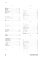
Index ............................................................................................................................. 129


1
Quick Reference
The Keysight N5700 DC Power Supplies – At a Glance ............... 10
The Front Panel - At a Glance ....................................................... 12
The Rear Panel – At a Glance ........................................................ 14
This chapter concisely describes the Keysight Technologies Series
N5700 Power Supplies.
This chapter is not meant to describe every operating feature in detail. It
is simply a quick reference guide to quickly become familiar with the
essential components of the power supply. It can also be used as a
memory jogger for experienced users to quickly find a front/rear panel
function.
A quick reference programming command chart is included in the
beginning of chapter 5.

1 Quick Reference
10 Series N5700 User’s Guide
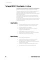
The Keysight N5700 DC Power Supplies – At a Glance
The Keysight Technologies Series N5700 System DC Power Supplies are
general-purpose, 1U (rack unit) high, switching power supplies that are
available with a wide variety of output voltage and current ratings.
These power supplies are power-factor corrected and operate from a
worldwide AC voltage range. Output voltage and current are
continuously displayed and LED indicators show the complete operating
status of the power supply.
The front panel controls allow the user to set the output parameters,
over-voltage, under-voltage, and over-current protection levels, and
preview the settings.
The rear panel includes the necessary connectors to control and monitor
the power supply operation by analog signals or by the built-in remote
communication interfaces.
Output Features
• Constant voltage/constant current with automatic crossover.
• High-resolution voltage and current front panel controls.
• Accurate voltage and current readback.
• Independent edge-triggered external shut-off, and level-
triggered external enable/disable.
• Parallel operation with active current sharing.
• Remote sensing to compensate for voltage drop in load leads.
• Analog output programming and monitoring.
System Features
• Built-in GBIB/LAN/USB interface.
• A built-in Web server that lets you control the instrument
directly from an internet browser on your computer.
• Zero-gap stacking - no ventilation holes at the top and bottom
surface of the power supply.
• Universal input voltage with active power factor correction.
• Fan speed control for low noise and extended fan life.

Quick Reference 1
Series N5700 User’s Guide 11
Programmable Functions
• Output voltage and current setting.
• Output voltage and current measurement.
• Output voltage and current trigger setting.
• Output On/Off control.
• Over-current protection setting.
• Over-voltage protection setting and readback.
• Under-voltage limit setting and readback.
• Start-up mode (either last setting or reset mode)
• Status register setting and readback.
• Bus trigger
• Calibration
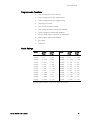
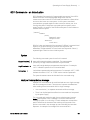
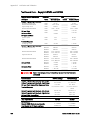
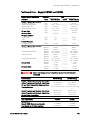
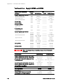
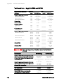
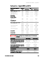
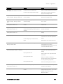
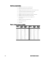
Model Ratings
Model
Voltage
Range
Current
Range
Model
Voltage
Range
Current
Range
N5741A
0 – 6V
0 – 100A
N5761A
0 – 6V
0 – 180A
N5742A
0 – 8V
0 – 90A
N5762A
0 – 8V
0 – 165A
N5743A
0 – 12.5V
0 – 60A
N5763A
0 – 12.5V
0 – 120A
N5744A
0 – 20V
0 – 38A
N5764A
0 – 20V
0 – 76A
N5745A
0 – 30V
0 – 25A
N5765A
0 – 30V
0 – 50A
N5746A 0 – 40V 0 – 19A N5766A 0 – 40V 0 – 38A
N5747A 0 – 60V 0 – 12.5A N5767A 0 – 60V 0 – 25A
N5748A 0 – 80V 0 – 9.5A N5768A 0 – 80V 0 – 19A
N5749A 0 – 100V 0 – 7.5A N5769A 0 – 100V 0 – 15A
N5750A 0 – 150V 0 – 5A N5770A 0 – 150V 0 – 10A
N5751A 0 – 300V 0 – 2.5A N5771A 0 – 300V 0 – 5A
N5752A 0 – 600V 0 – 1.3A N5772A 0 – 600V 0 – 2.5A
Minimum output voltage is ≤ 0.2% of the rated output voltage.
Minimum output current is ≤ 0.4% of the rated output current.

1 Quick Reference
12 Series N5700 User’s Guide
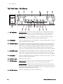
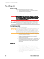
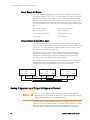
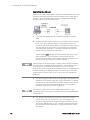
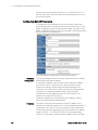
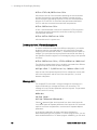
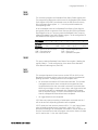
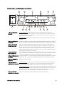
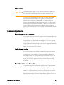
The Front Panel - At a Glance
VOLTAGE
PROT FINE LIMIT/ OVP
UVL OCP/488 LAN OUT ON
DC AMPS
CURRENT
DC VOLTS
POWER
1
14
17
18
19
2
15
16
3
13
10
4
11
5
12
9
6
7
8
CV CC
1 – VOLTAGE knob
Voltage function: Adjusts the output voltage, the over-voltage protection level,
and the under-voltage limit. If over-voltage protection or under-voltage limits
have been set, you cannot program the output voltage outside those limits.
GPIB address: Selects the GPIB address when OCP/488 is pressed and held.
Units purchased with Option NGP do not have a GPIB interface.
2 – CV indicator
When lit, indicates that the unit is operating in constant voltage mode – with the
output voltage being held constant.
3 – DC VOLTS display
LED display that normally displays the voltage measured at the sense terminals.
When LIMIT is pressed, the display indicates the programmed voltage setting.
When OVP/UVL is pressed, the display indicates either the OVP or UVL setting.
When OCP/488 is pressed and held, the display indicates the GPIB address.
When LAN is pressed and held, the display indicates the IP and Ethernet address.
4 – DC AMPS display
LED display that normally displays the current measured at the output terminals.
When LIMIT is pressed, the display indicates the programmed current setting.
When LAN is pressed and held, the display indicates the IP and Ethernet address.
5 – CC indicator
When lit, indicates that the unit is operating in constant current mode – with the
output current being held constant.
6 – CURRENT knob
Adjusts the output current.
7 – OUT ON button
Output function: Press OUT ON to turn the output on or off. Press OUT ON to
reset and turn the output on after an OVP or OCP event has occurred.
Start-up function: Selects between Safe-Start and Auto-Restart modes. Press
and hold the OUT ON button to toggle between Safe-Start and Auto-Restart. The
display cycles between SAF and AU7. Releasing the OUT ON button while one of
the modes is displayed selects that mode.
8 – OUT ON indicator
When lit, indicates that the output is enabled or on.

Quick Reference 1
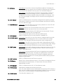
Series N5700 User’s Guide 13
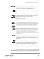
9 – LAN button
View address: Press LAN to view the IP and Ethernet address. The display first
scrolls through the four segments of the IP address, followed by the six segments
of the Ethernet (EA) address. Press any key to turn the address display off.
Reset address: Press and hold the LAN button for three seconds. Pressing the
LAN button again while the message “LAn rES” is displayed resets the LAN
configuration to the factory-shipped settings (see chapter 4 for settings). If the
key is not pressed again, the display returns to normal and the configuration is
not changed.
10 – LAN indicator
When lit, indicates that the LAN has been configured and is operating normally.
When blinking, identifies the unit for which the indicator has been set to blink by
the unit’s Web server page.
11 – OCP/488 button
Enable OCP: Press OCP/488 to turn over-current protection on. Press OCP/488
again to turn over-current protection off.
Reset OCP: When an over-current protection event occurs, press the OUT ON
button to enable the output and re-arm over-current protection.
GPIB address: Press and hold the OCP/488 button for three seconds. This lets
you set the GPIB address with the Voltage knob.
Units purchased with Option NGP do not have a GPIB interface.
12 – OCP indicator
When lit, indicates that over-current protection is enabled or on.
13 – OVP/UVL button
OVP function: Press OVP/UVL once to set the over-voltage protection level with
the Voltage knob (the display shows OUP). You cannot set the over-voltage
protection lower than about 5% above the present output voltage setting.
UVL function: Press OVP/UVL twice to set the under-voltage programming limit
with the Voltage knob (the display shows UUL). You cannot set the under-voltage
protection higher than about 5% below the present output voltage setting.
14 – LIMIT button
Limit function: Press LIMIT to display the output voltage and current limit. For five
seconds the display shows the settings and then it returns to show the actual
output voltage and current.
Lock function: Press and hold the LIMIT button to toggle between Locked front
panel and Unlocked front panel. The display will cycle between LFP and UFP.
Releasing the LIMIT button while one of the modes is displayed selects that
mode. If the display indicates rLFP, the front panel has been locked by a remote
programming command.
15 – LIMIT indicator
When lit, indicates that the LIMIT button is pressed.
16 – FINE button
Selects Fine or Coarse adjustment control. In Fine mode, the Voltage and Current
knobs operate with high resolution; in Coarse mode, with lower resolution
(approximately six turns).
17 – FINE indicator
When lit, indicates that the unit is in Fine adjustment mode.
18 – PROT indicator
When blinking, indicates that a fault has occurred.
OVP, OCP, OTP, Enable fail, and AC fail detection will cause the PROT indicator to
blink. The PROT indicator may blink and the display indicate AC for a few seconds
after the unit is turned off because of residual energy inside the unit.
19 – POWER switch
Turns the power supply on or off.

1 Quick Reference
14 Series N5700 User’s Guide
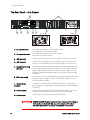
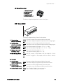
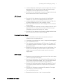
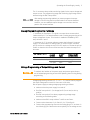
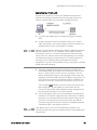
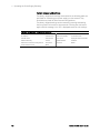
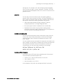
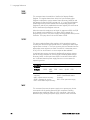
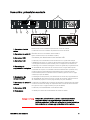
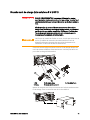
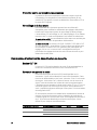
The Rear Panel – At a Glance
9
5
73
8
4
61
2
750W
1500W6V - 60V
80V - 600V
AC INPUT
ON
OFF
+V -V
NOT ACTIVE
J2 SW1 GPIB
ANALOG PROGRAMMING
+S+LS NC -LC-S
1 2 3 4 5 6 7 8 9
10/100 Ethernet
LINK TX
J1
!!
1 – AC input connector
Wire clamp connector for 1500W output models.
IEC connector for 750W output models.
2 – DC output connector
Wire clamp connector for 80V to 600V models.
Bus bars for 6V to 60V models.
3 – USB connector
Connector for connecting to a USB interface. See chapter 4 for setup.
4 – LAN connector
Connector for connecting to a LAN interface. LINK LED indicates link
integrity. TX LED indicates LAN activity. See chapter 4 for LAN setup.
5 – Analog Programming
connector
Connector for the analog interface. Includes output voltage and current
limit programming and monitoring signals, Shut-Off control (electrical
signal), Enable/Disable control (dry-contact), power supply ok (Power
Supply OK) signal and operation mode (CV/CC) signal. (See next page
for details)
6 – SW1 setup switch
Nine-position switch for selecting remote programming and monitoring
modes for Output Voltage, Current Limit and other control functions.
(See next page for details)
7 – Remote Sense
connector
Connector for making remote sensing connections for regulating the
load voltage and compensating for wiring voltage drop. (See next page
for details)
8 – GPIB connector
Connector for connecting to a GPIB interface. See chapter 4 for setup.
Units purchased with Option NGP do not have a GPIB interface.
9 – Ground screw
M4x8 screws for making chassis ground connections
WARNING
SHOCK HAZARD
The power cord provides a chassis ground through a
third conductor. Be certain that your power outlet is of the three-
conductor type with the correct pin connected to earth ground

Quick Reference 1
Series N5700 User’s Guide 15
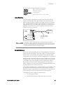
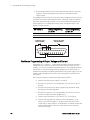
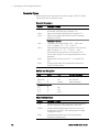
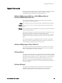
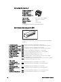
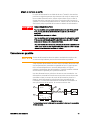
J2 Sense Connector
1 – Remote sense (+)
2 – Local sense (+)
3 – Not used
4 – Local sense (–)
5 – Remote sense (–)
The factory-shipped configuration is shown in the figure.
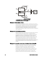
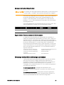
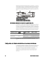
SW1 Setup Switch
The factory-shipped setting is Down for all switches.
1 – Output voltage,
voltage programming
Down: The output voltage is programmed by the front panel.
Up: The output voltage is programmed by the external voltage signal.
2 – Output current,
current programming
Down: The output current is programmed by the front panel.
Up: The output current is programmed by the external voltage signal.
3 – Programming range
(voltage/resistance)
Down: The remote programming range is: 0 – 5V / 0 – 5K
Ω
.
Up: The remote programming range is: 0 – 10V / 0 – 10K
Ω
.
4 – Voltage and Current
monitoring range
Down: The remote monitoring range is: 0 – 5V.
Up: The remote monitoring range is: 0 – 10V.
5 – Shut-Off Logic Select
Down: OUT OFF = Low (0 – 0.6V) or short; OUT ON = High (2V – 15V) or
open.
Up: OUT OFF = High (2V – 15V) or open; OUT ON = Low (0 – 0.6V) or
short.
6 – Not Used
7 – Output voltage,
resistive programming
Down: The output voltage is programmed by the front panel.
Up: The output voltage is programmed by the external resistor.
8 – Output current,
resistive programming
Down: The output current is programmed by the front panel.
Up: The output current is programmed by the external resistor.
9 – Enable/Disable control
Down: The J1 Enable+/Enable– pins are not active.
Up: The J1 Enable+/Enable– pins are active.
123456789

1 Quick Reference
16 Series N5700 User’s Guide
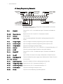
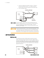
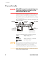
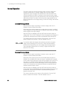
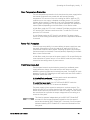
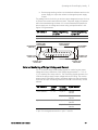
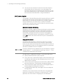
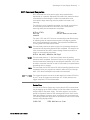
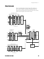
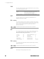
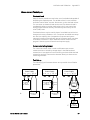
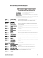
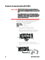
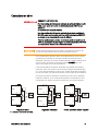
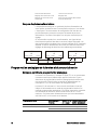
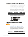
J1 Analog Programming Connector
The factory-shipped default configuration is Local operation, which does
not require connection to J1.
Pin 1:
Enable IN
Connect Pin 1 to Pin 14 to enable the output. Disconnect to disable the
output.
Pin 2, 3:
Chassis Common
Signal return for Pin 15 and Pin 16. Connected to chassis.
Pin 4–7:
Not Used
No connection
Pin 8:
Local/Analog
Input for selecting between front panel or analog programming of the
output.
Pin 9:
Voltage Program
Input for voltage or resistance programming of the output voltage.
Pin 10:
Current Program
Input for voltage or resistance programming of the output current.
Pin 11:
Voltage Monitor
Output for monitoring the output voltage.
Pin 12:
Common
Signal return for Pin 8, Pin11, Pin 13, and Pin 24. Connected internally to –S.
Pin 13:
CV/CC
Output for constant voltage/constant current mode indication.
Pin 14:
Enable OUT
Connect Pin 14 to Pin 1 to enable the output. Disconnect to disable the
output.
Pin 15:
Shut Off
Input for Shut-Off control of the output. Referenced to Chassis Common.
Pin 16:
Power Supply OK
Output to indicate the power supply status. Referenced to Chassis Common.
Pin 17–20:
Not Used
No connection
Pin 21:
Local/Analog State
Output for indication of local or analog programming mode.
Pin 22:
Voltage Prog. Return
Signal return for Pin 9. Connected internally to –S.
Pin 23:
Current Prog. Return
Signal return for Pin 10. Connected internally to –S.
Pin 24:
Current Monitor
Output for monitoring the output current.
Pin 25:
Parallel
Output for current balancing in parallel operation.
141516
1718
19
2021
2223
24
25
1
2
3
45
6
7
8
101112
13 9
Current Monitor
Current Prog. Return
Voltage Prog. Return
Local / Analog State
Chassis Common
Enable IN
Voltage Monitor
Common (-S)
CV / CC
Current Program
Voltage Program
Local / Analog
Parallel Enable OUT
Shut Off
Power Supply OK
Chassis Common

2
Installation
General Information ....................................................................... 18
Inspecting the Unit ......................................................................... 19
Installing the Unit ........................................................................... 19
Connecting the Line Cord .............................................................. 21
Connecting the Load ...................................................................... 23
Output Voltage Sensing ................................................................. 26
Load Considerations ....................................................................... 28
Parallel Connections ...................................................................... 30
Series Connections ......................................................................... 32
J1 Connector Connections ............................................................ 34
This chapter describes how to install your power supply. It discusses
installation, rack mounting, and line cord connections.
This chapter also discusses how to connect your load to the output
terminals. It discusses what you need to know about wire sizes and how
to compensate for voltage drops in the load leads. It also discusses
various loads configurations and how to connect units in series and
parallel.
Before getting started, check the list under “Items Supplied” and verify
that you have received these items with your instrument. If anything is
missing, please contact your nearest Keysight Sales and Service Office.

2 Installation
18 Series N5700 User’s Guide
General Information
Models
750 W Models
1500 W Models
N5741A – N5749A N5761A – N5769A
N5750A – N5752A N5770A – N5772A
Items Supplied
Item
Description
Power Cord
A power cord appropriate for your location
750W units are supplied with terminated power cords
1500W units are supplied with unterminated power
cords
Strain relief assembly A strain relief assembly for unterminated power cords
(only used for 1500W units)
AC input cover A cover for the AC input on which the strain relief
assembly is mounted (only used for 1500W units)
Analog connector A DB25 subminiature connector plug for analog
control connections
Shield assembly A shield for the output terminal connections
Hardware Nuts, washers, and bolts for connecting load leads to
output bus bars (only used for 6V to 60V units)
Certificate of
Calibration
A certificate of calibration referenced to the serial
number
Accessories
Item
Description
N5740A Rack-mount slide kit for installing in system II cabinets

Installation 2
Series N5700 User’s Guide 19
Inspecting the Unit
When you receive your power supply, inspect it for any obvious damage
that may have occurred during shipment. If there is damage, notify the
shipping carrier and nearest Keysight Sales and Service Office
immediately. Refer to Appendix C for more information.
Until you have checked out the power supply, save the shipping carton
and packing materials in case the unit has to be returned.
Installing the Unit
Safety Considerations
This power supply is a Safety Class 1 instrument, which means it has a
protective earth terminal. That terminal must be connected to earth
ground through power source equipped with a ground receptacle. Refer
to the Safety Summary page at the beginning of this guide for general
safety information. Before installation or operation, check the power
supply and review this guide for safety warnings and instructions. Safety
warnings for specific procedures are located at appropriate places
throughout this Guide.
Environment
WARNING
Do not operate the instrument in the presence of flammable gasses or
fumes
The environmental conditions, dimensions of the instrument, as well as
an outline diagram are given in Appendix A. Basically, the instrument
should only be operated indoors in a controlled environment. Do not
operate the power supply in an area where the ambient temperature
exceeds 40° C.
NOTE
Keysight N5700 power supplies generate magnetic fields, which may
affect the operation of other instruments. If your equipment is
susceptible to magnetic fields, do not position it adjacent to the power
supply.
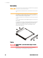
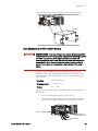
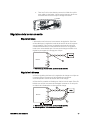
Airflow
Fans cool the power supply by drawing air through the front and
exhausting it out the back. The instrument must be installed in a location
that allows sufficient space of at least 10 cm (4 in) at the front and back
of the unit for adequate air circulation.

2 Installation
20 Series N5700 User’s Guide
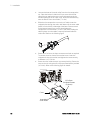
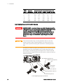
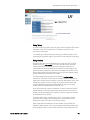
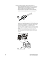
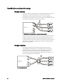
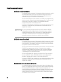
Rack Installation
CAUTION
Ensure that the screws used to attach the rack slide kit do not penetrate
more than 6 mm into the sides of the unit.
Do not block the air intake at the front, or the exhaust at the rear of the
unit.
The Keysight N5700 power supplies can be mounted in a standard 19-
inch rack panel or cabinet. They are designed to fit in one rack unit (1U)
of space. To install the power supply in a rack:
1. Use the front panel rack-mount brackets to install the power supply in
the rack.
2. Use a support bracket to provide adequate support for the rear of the
power supply.
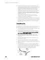
3. If using rack mount slides, use Keysight N5740A Rack-mount Slide Kit
to install the unit in a standard 19-inch equipment rack. Refer to the
following figure for assembly instructions. Use two #10-32 x 3/8 in
(max.) screws at each side. To prevent internal damage, use the
specified screw length only.
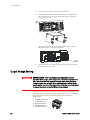
Cleaning
WARNING
SHOCK HAZARD
To prevent electric shock, unplug the unit before
cleaning.
Use a dry cloth or one slightly dampened with water to clean the
external case parts. Do not attempt to clean internally.
La page charge ...
La page charge ...
La page charge ...
La page charge ...
La page charge ...
La page charge ...
La page charge ...
La page charge ...
La page charge ...
La page charge ...
La page charge ...
La page charge ...
La page charge ...
La page charge ...
La page charge ...
La page charge ...
La page charge ...
La page charge ...
La page charge ...
La page charge ...
La page charge ...
La page charge ...
La page charge ...
La page charge ...
La page charge ...
La page charge ...
La page charge ...
La page charge ...
La page charge ...
La page charge ...
La page charge ...
La page charge ...
La page charge ...
La page charge ...
La page charge ...
La page charge ...
La page charge ...
La page charge ...
La page charge ...
La page charge ...
La page charge ...
La page charge ...
La page charge ...
La page charge ...
La page charge ...
La page charge ...
La page charge ...
La page charge ...
La page charge ...
La page charge ...
La page charge ...
La page charge ...
La page charge ...
La page charge ...
La page charge ...
La page charge ...
La page charge ...
La page charge ...
La page charge ...
La page charge ...
La page charge ...
La page charge ...
La page charge ...
La page charge ...
La page charge ...
La page charge ...
La page charge ...
La page charge ...
La page charge ...
La page charge ...
La page charge ...
La page charge ...
La page charge ...
La page charge ...
La page charge ...
La page charge ...
La page charge ...
La page charge ...
La page charge ...
La page charge ...
La page charge ...
La page charge ...
La page charge ...
La page charge ...
La page charge ...
La page charge ...
La page charge ...
La page charge ...
La page charge ...
La page charge ...
La page charge ...
La page charge ...
La page charge ...
La page charge ...
La page charge ...
La page charge ...
La page charge ...
La page charge ...
La page charge ...
La page charge ...
La page charge ...
La page charge ...
La page charge ...
La page charge ...
La page charge ...
La page charge ...
La page charge ...
La page charge ...
La page charge ...
La page charge ...
La page charge ...
La page charge ...
La page charge ...
La page charge ...
La page charge ...
La page charge ...
La page charge ...
La page charge ...
La page charge ...
La page charge ...
La page charge ...
La page charge ...
La page charge ...
La page charge ...
La page charge ...
La page charge ...
La page charge ...
La page charge ...
La page charge ...
La page charge ...
La page charge ...
La page charge ...
La page charge ...
La page charge ...
La page charge ...
La page charge ...
La page charge ...
La page charge ...
La page charge ...
La page charge ...
La page charge ...
La page charge ...
La page charge ...
-
 1
1
-
 2
2
-
 3
3
-
 4
4
-
 5
5
-
 6
6
-
 7
7
-
 8
8
-
 9
9
-
 10
10
-
 11
11
-
 12
12
-
 13
13
-
 14
14
-
 15
15
-
 16
16
-
 17
17
-
 18
18
-
 19
19
-
 20
20
-
 21
21
-
 22
22
-
 23
23
-
 24
24
-
 25
25
-
 26
26
-
 27
27
-
 28
28
-
 29
29
-
 30
30
-
 31
31
-
 32
32
-
 33
33
-
 34
34
-
 35
35
-
 36
36
-
 37
37
-
 38
38
-
 39
39
-
 40
40
-
 41
41
-
 42
42
-
 43
43
-
 44
44
-
 45
45
-
 46
46
-
 47
47
-
 48
48
-
 49
49
-
 50
50
-
 51
51
-
 52
52
-
 53
53
-
 54
54
-
 55
55
-
 56
56
-
 57
57
-
 58
58
-
 59
59
-
 60
60
-
 61
61
-
 62
62
-
 63
63
-
 64
64
-
 65
65
-
 66
66
-
 67
67
-
 68
68
-
 69
69
-
 70
70
-
 71
71
-
 72
72
-
 73
73
-
 74
74
-
 75
75
-
 76
76
-
 77
77
-
 78
78
-
 79
79
-
 80
80
-
 81
81
-
 82
82
-
 83
83
-
 84
84
-
 85
85
-
 86
86
-
 87
87
-
 88
88
-
 89
89
-
 90
90
-
 91
91
-
 92
92
-
 93
93
-
 94
94
-
 95
95
-
 96
96
-
 97
97
-
 98
98
-
 99
99
-
 100
100
-
 101
101
-
 102
102
-
 103
103
-
 104
104
-
 105
105
-
 106
106
-
 107
107
-
 108
108
-
 109
109
-
 110
110
-
 111
111
-
 112
112
-
 113
113
-
 114
114
-
 115
115
-
 116
116
-
 117
117
-
 118
118
-
 119
119
-
 120
120
-
 121
121
-
 122
122
-
 123
123
-
 124
124
-
 125
125
-
 126
126
-
 127
127
-
 128
128
-
 129
129
-
 130
130
-
 131
131
-
 132
132
-
 133
133
-
 134
134
-
 135
135
-
 136
136
-
 137
137
-
 138
138
-
 139
139
-
 140
140
-
 141
141
-
 142
142
-
 143
143
-
 144
144
-
 145
145
-
 146
146
-
 147
147
-
 148
148
-
 149
149
-
 150
150
-
 151
151
-
 152
152
-
 153
153
-
 154
154
-
 155
155
-
 156
156
-
 157
157
-
 158
158
-
 159
159
-
 160
160
-
 161
161
-
 162
162
-
 163
163


Keysight Technologies N5752A Manuel utilisateur
- Catégorie
- Blocs d'alimentation
- Taper
- Manuel utilisateur
dans d''autres langues
Autres documents
-
HP 664xA Manuel utilisateur
-
 Xantrex XDL 35-5TP Manuel utilisateur
-
HP 655xa Manuel utilisateur
-
 TDK-Lambda RFE1600-24/S Guide d'installation
-
EXFO LTB Series Mode d'emploi
-
Tektronix MSO5054 Le manuel du propriétaire
-
Tektronix DPO4034B Le manuel du propriétaire
-
Agilent Technologies E3614A Manuel utilisateur
-
 TA Instruments ARES-G2 Getting Started Manual
-
BEL TXP3500/4000 Guide d'installation


