
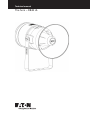
The horn – DB3B UL
Technical manual

ii THE HORN – DB3B UL TM261 April 2020 www.eaton.com
DISCLAIMER OF WARRANTIES AND LIMITATION OF LIABILITY
The information, recommendations, descriptions and safety notations in this document are based on Eaton Corporation’s
(“Eaton”) experience and judgment and may not cover all contingencies. If further information is required, an Eaton sales
office should be consulted. Sale of the product shown in this literature is subject to the terms and conditions outlined in
appropriate Eaton selling policies or other contractual agreement between Eaton and the purchaser.
THERE ARE NO UNDERSTANDINGS, AGREEMENTS, WARRANTIES, EXPRESSED OR IMPLIED, INCLUDING
WARRANTIES OF FITNESS FOR A PARTICULAR PURPOSE OR MERCHANTABILITY, OTHER THAN THOSE
SPECIFICALLY SET OUT IN ANY EXISTING CONTRACT BETWEEN THE PARTIES. ANY SUCH CONTRACT STATES THE
ENTIRE OBLIGATION OF EATON. THE CONTENTS OF THIS DOCUMENT SHALL NOT BECOME PART OF OR MODIFY
ANY CONTRACT BETWEEN THE PARTIES.
In no event will Eaton be responsible to the purchaser or user in contract, in tort (including negligence), strict liability or
other-wise for any special, indirect, incidental or consequential damage or loss whatsoever, including but not limited to
damage or loss of use of equipment, plant or power system, cost of capital, loss of power, additional expenses in the
use of existing power facilities, or claims against the purchaser or user by its customers resulting from the use of the
information, recommendations and descriptions contained herein. The information contained in this manual is subject to
change without notice.

iiiTHE HORN – DB3B UL TM261 April 2020 www.eaton.com
The horn – DB3B UL
English
Contents
1.0 INTRODUCTION . . . . . . . . . . . . . . . . . . . . . . . . . . . . . . . . . . . . . . . . . . . . . . . . . . . . . . . . . . . . . . . . . . . . . .1
2.0 GENERAL SAFETY MESSAGES AND WARNINGS . . . . . . . . . . . . . . . . . . . . . . . . . . . . . . . . . . . . . . . . . .1
3.0 INSTALLATION . . . . . . . . . . . . . . . . . . . . . . . . . . . . . . . . . . . . . . . . . . . . . . . . . . . . . . . . . . . . . . . . . . . . . . .1
Access to terminals . . . . . . . . . . . . . . . . . . . . . . . . . . . . . . . . . . . . . . . . . . . . . . . . . . . . . . . . . . . . . . . . . . . . . . . . . . 1
Wiring details. . . . . . . . . . . . . . . . . . . . . . . . . . . . . . . . . . . . . . . . . . . . . . . . . . . . . . . . . . . . . . . . . . . . . . . . . . . . . . . 2
AC version wiring details (Types 1 & 2) . . . . . . . . . . . . . . . . . . . . . . . . . . . . . . . . . . . . . . . . . . . . . . . . . . . . . . . . . . . 2
DC version – 3 stage without monitoring wiring details (Type 3) . . . . . . . . . . . . . . . . . . . . . . . . . . . . . . . . . . . . . . . 2
DC version – Dual stage common +ve with monitoring (standard configuration) wiring details (Type 4) . . . . . . . . 3
DC Version – Up to 3 user selectable stages with 2 independantly powered stages (Type 5) 3
DC version – Up to 3 stage with or without monitoring (alternative configuration) wiring details (Type 6) . . . . . . . 4
DC version with voltage free stage activation wiring details (Type 7) . . . . . . . . . . . . . . . . . . . . . . . . . . . . . . . . . . . 4
4.0 OPERATION . . . . . . . . . . . . . . . . . . . . . . . . . . . . . . . . . . . . . . . . . . . . . . . . . . . . . . . . . . . . . . . . . . . . . . . . .5
Directional characteristics: . . . . . . . . . . . . . . . . . . . . . . . . . . . . . . . . . . . . . . . . . . . . . . . . . . . . . . . . . . . . . . . . . . . . . 5
5.0 MAINTENANCE . . . . . . . . . . . . . . . . . . . . . . . . . . . . . . . . . . . . . . . . . . . . . . . . . . . . . . . . . . . . . . . . . . . . . .9
6.0 CERTIFICATION/APPROVALS . . . . . . . . . . . . . . . . . . . . . . . . . . . . . . . . . . . . . . . . . . . . . . . . . . . . . . . . . .10
Electrical ratings: . . . . . . . . . . . . . . . . . . . . . . . . . . . . . . . . . . . . . . . . . . . . . . . . . . . . . . . . . . . . . . . . . . . . . . . . . . . .10
7.0 SPECIAL CONDITIONS FOR SAFE USE . . . . . . . . . . . . . . . . . . . . . . . . . . . . . . . . . . . . . . . . . . . . . . . . . . 10
8.0 FUNCTIONAL SAFETY ...............................................................11
Introduction ................................................................................11
Assessment of functional safety ................................................................11
Conditions of safe use ....................................................................... 12

iv THE HORN – DB3B UL TM261 April 2020 www.eaton.com

1THE HORN – DB3B UL TM261 April 2020 www.eaton.com
The horn – DB3B UL
English
1.0 Introduction
This range of horns, suitable for fire alarm or general use,
is intended for use in potentially explosive gas (G) or gas
and dust (GD) atmospheres.
The enclosure is manufactured from a UV stable glass
reinforced polyester with a rugged thermoplastic flare.
Stainless steel mounting bracket, cover screws and
fixings are incorporated throughout thus ensuring a
corrosion free product.
A UL ordinary locations listed version is also available for
use in non-explosive atmospheres.
2.0 General safety messages and
warnings
All instructions and safety messages in this manual must
be followed to allow safe installation of the device. The
device must only be installed and maintained by correctly
trained site personnel/installers.
I. To reduce the risk of ignition of hazardous
atmospheres and shock, do not apply power to the
device until installation has been completed and the
device is fully sealed and secured.
II. To reduce the risk of ignition of hazardous
atmospheres and shock, keep device tightly closed
when the circuit is energised.
III. Before removing the cover for installation or
maintenance, ensure that the power to the device
isisolated.
IV. Following installation, test the device to ensure
correct operation.
V. Following installation ensure a copy of this manual
ismade available to all operating personnel.
VI. When installing the device, requirements for
selection, installation and operation should be
referred to e.g. IEE Wiring Regulations and the
‘National Electrical Code’ in North America. Additional
national and/or local requirements may also apply.
VII. Cable termination should be in accordance with the
specification applying to the required application.
MEDC recommends that all cables and cores should
be correctly identified. Please refer to the wiring
diagram in this manual (or separate diagram provided
with the unit).
VIII. This is an Ex d product, correctly listed or certified
explosion proof cable glands and stopping plugs must
be used.
IX. Ensure that only the correct listed or certified
stopping plugs are used to blank off unused gland
entry points and that the NEMA/IP rating of the unit
is maintained.
X. MEDC recommend the use of a sealing compound
such as HYLOMAR PL32 on the threads of all glands
and stopping plugs and/or a suitable sealing washer
in order to maintain the IP rating of the unit.
XI. The internal earth terminal
must be used for
protective earthing when required. Do not remove
the internal ground strap from the earth terminal
where fitted.
For units with metric entries; gland continuity and
earthing my be achieved with an optional external
earth plate. If the external plate is fitted, a thread
sealing compound such as HYLOMAR PL32 must be
employed to maintain the IP rating of the unit.
XII. When installing the device, MEDC recommends the
use of stainless steel fasteners. Ensure that all nuts,
bolts and fixings are secure.
XIII. The unit should be positioned such that debris, dust
or water cannot settle in the re-entrant horn.
XIV. The unit should be positioned such that any solid
object, not part of the equipment, is a minimum of
40mm from the Ex d flamepath joint.
3.0 Installation
The unit is mounted via 2 off Ø23/64” (Ø9mm) fixing
holes in the U-shaped stirrup/mounting bracket. If
required, the unit can be initially placed via the Ø33/64”
(Ø13mm) central hole in the stirrup. The unit can then
berotated to the required position and fixed via the
otherholes.
If ordered with the unit, a swivel mounting bracket option
is available to allow further rotational adjustment to
the unit.
The fixing holes have been designed to accept an Ø5/16”
(M8) screw or bolt.
Access to terminals
The cover is secured with 6 off M5 cover screws
(4.0mm A/F hexagon key). Once the cover fixings are
unscrewed, the cover can be lifted away from the
enclosure to gain access to the interior. The cover fixings
are captive and will remain in the cover.
Once termination is complete, carefully replace the
cover assembly back onto the body, avoiding damage to
the mating surfaces. Tighten the cover screws evenly.
Ensure the O-ring is seated correctly on the cover during
reassembly. Ensure the required maximum gap of
0.0015” (0.038mm) is maintained between the cover and
the enclosure body once assembled.

2 THE HORN – DB3B UL TM261 April 2020 www.eaton.com
The horn – DB3B UL
English
Wiring details
The unit is available in a number of basic configurations:
1. AC input, single stage.
2. AC input, dual stage with voltage-free stage selection.
3. DC input, up to 3 user selectable stages without
monitoring.
4. DC input, up to 2 user selectable stages with
EOL/monitoring (standard configuration).
5. DC input, up to 3 user selectable stages with 2
independantly powered stages.
6. DC input, up to 3 user selectable stages with optional
EOL/monitoring (alternative configuration).
7. DC input, 5 user selectable stages with voltage free
stage selection with or without monitoring.
AC version wiring details (Types 1 & 2)
• Type 1: Connect the live and neutral supply wires to
the terminals as detailed in the wiring diagram. The
unit will be supplied with the link between R1 and R0
fitted to the terminals. When power is applied to the
unit, the stage 1 tone will be produced as selected
on the 5- way DIP switch.
• Type 2: Connect the live and Neutral supply wires
to the terminals as detailed in the wiring diagram.
The unit will be supplied with no link fitted between
R1 and R0. Connect wires and remote switches to
terminals R0, R1 and R2 as shown. When power is
initially applied to the unit, no tone will be produced.
When the switch connected to R1 is closed, the
stage 1 tone will be produced as selected by the
5-way DIP switch on the electronics assembly.
When the switch connected to R2 is closed, the
pre-selected tone for stage 2 is produced. See tone
table 2 for details of pre-selected tones.
ote: N Closing both switches will produce no tone.
DC version – 3 stage without monitoring wiring
details (Type 3)
This type can be configured in a number of different ways
depending on requirements. Independent tone selection
for all 3 stages is via the 3 off 5-way DIP switches fitted
to the electronics assembly:
• 2-wire system (Single stage): Connect the positive
and negative supply wires to the terminals as detailed
in the wiring diagram.
• 2-wire system (Dual stage, reverse polarity):
Connect the positive and negative supply wires to
the terminals as detailed in the wiring diagram. The
second stage is produced by reversing the polarity of
the supply to the unit.
• 3-wire system (Dual stage, common +ve): Connect
3 supply wires to the terminals as detailed in the
wiring diagram (1 common +ve wire and 2 -ve wires).
Stage 1 is produced when power is applied across the
common +ve and stage 1 -ve terminals. Stage 2 is
produced when power is applied across the common
+ve and stage 2 -ve terminals.
• 3-wire system (Dual stage, common -ve): Connect
3 supply wires to the terminals as detailed in the
wiring diagram (2 +ve wires and 1 common -ve wire).
Stage 1 is produced when power is applied across
the stage 1 +ve and common -ve terminals. Stage 2
is produced when power is applied across the stage 2
+ve and stage common -ve terminals.
• 4-wire system (Triple stage, Common -ve): Connect
4 supply wires to the terminals as detailed in the
wiring diagram (3 +ve wires and 1 common -ve wire).
Stage 1 is produced when power is applied across
the stage 1 +ve and common -ve terminals. Stage 2
is produced when power is applied across the stage 2
+ve and common -ve terminals. Stage 3 is produced
when power is applied across the stage 3 +ve and
common -ve terminals.
All versions are supplied with terminals to allow
loop-in loop-out connection of the supply wires.

3THE HORN – DB3B UL TM261 April 2020 www.eaton.com
The horn – DB3B UL
English
DC version – Dual stage common +ve with
monitoring (standard configuration) wiring
details (Type 4)
Connect up to 4 supply wires to the terminals as detailed
in the wiring diagram. Stage 1 is produced when power
is applied across the common +ve and stage 1 -ve
terminals. Stage 2 is produced when power is applied
across the common +ve and stage 2 -ve terminals.
Monitoring functionality is obtained when the supply is
connected across M1 & M2 terminals.
ote: N monitored terminals are not polarity dependent
DC Version – Up to 3 user selectable stages
with 2 independantly powered stages (Type 5)
Connect up to 4 supply wires to the terminals as detailed
in the wiring diagram. Stage 1 is produced when power is
applied across the stage 1 terminals. Stage 2 is produced
when power is applied across the stage 2 terminals.
Stages 1 and 2 may be powered from independent
supplies. Stage 3 is produced when power is applied to
both the stage 1 and stage 2 terminals.
Resistors may be added to the terminals as shown for
monitoring purposes. Monitoring functionality is available
at all times if a suitable monitoring relay is used in
the system.

4 THE HORN – DB3B UL TM261 April 2020 www.eaton.com
The horn – DB3B UL
English
DC version – Up to 3 stage with or without mon-
itoring (alternative configuration) wiring details
(Type 6)
ote: N This alternative configuration must be specified
when ordering the unit.
This type can be connected either as a three stage
common –ve configuration, or if an optional EOL is
specified if can be configured as a dual stage common
–ve system with monitoring.
• 4-wire system (Triple stage, Common +ve): Connect
4 supply wires to the terminals as detailed in the
wiring diagram (1 common +ve wire and 3 -ve wires).
Stage 1 is produced when power is applied across the
common +ve and stage 1 -ve terminals. Stage 2 is
produced when power is applied across the common
+ve and stage 2 -ve terminals. Stage 3 is produced
when power is applied across the common +ve and
stage 3 -ve terminals.
• 4-wire system (Dual stage, common –ve with
monitoring): Connect 4 supply wires to the terminals
as detailed in the wiring diagram. Stage 1 is produced
when power is applied across the common -ve and
stage 1 +ve terminals. Stage 2 is produced when
power is applied across the common -ve and stage 2
+ve terminals.
Monitoring functionality is obtained when the supply is
connected across M1 & M2 terminals.
ote: N monitored terminals are not polarity dependents
DC version with voltage free stage activation
wiring details (Type 7)
Connect the positive (+ve) and negative (-ve) supply wires
to the terminals as detailed in the wiring diagram. When
power is applied to the unit, no tone will be produced
initially. Connect wires and remote switches to terminals
R0 to R5 as shown. When the switch connected to R1 is
closed, the stage 1 tone will be produced as selected by
the 5-way DIP switch on the electronics assembly. When
any of the other switches connected to R2 to R5 is closed,
the pre- selected tone for stages 2 to 5 are produced.
See tone table 2 for details of pre-selected tones.
ote: N Closing more than one switch at a time will result
in no tone being produced.
#
4.0 Operation
The sounder is available in various AC and DC input
voltage versions.
For AC versions, 120Vac and 240Vac units comply with
regulated supply limits, for all other AC versions, the
nominal operating voltage is stated on the unit label and
the supply voltage tolerance is ±10%.
For 12-48Vdc versions, the absolute input voltage range is
11.0Vdc to 58.0Vdc.
The unit is fitted with a volume control which is
positioned on the top face of the electronics assembly
PCB. Maximum volume is obtained when this control is
turned fully clockwise. When turned fully anti-clockwise
the unit will emit no sound. For fire alarm use, if the
control is not set to maximum volume, ensure the output
from the horn meets the minimum level required by the
relevant standards.
Warning: Do not attempt to turn the volume control past
its limits of movement as this may cause damage to
the unit.

5THE HORN – DB3B UL TM261 April 2020 www.eaton.com
The horn – DB3B UL
English
Stages
For all versions, a 5-way DIP switch selects the stage required for each stage. The settings for the standard stages are
shown in the table below:
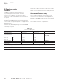
Tone table 1:
Tone no. Tone freq/description Switch setting 12345 Tone description
1 Alt Stages 800/970 Hz at 1/4 sec 11111
2 Sweeping 800/970 Hz at 7 Hz 11110 Fast Sweep (LF)
3 Sweeping 800/970 Hz at 1 Hz 11101 Medium Sweep (LF)
4 Continuous at 2850 Hz 11100
5 Sweeping 2400-2850 Hz at 7 Hz 11011 Fast Sweep
6 Sweeping 2400-2850 Hz at 1 Hz 11010
7 Slow Whoop 11001 Slow Whoop
8 Sweep 1200-500 Hz at 1 Hz 11000 Din Stage
9 Alt Stages 2400/2850 Hz at 2 Hz 10111
10 Int Stage of 970 Hz at 1 Hz 10110 Back-up Alarm (LF)
11 Alt Stages 800/970 Hz at 7/8 Hz 10101
12 Int Stage at 2850 Hz at 1Hz 10100 Back-up Alarm (HF)
13 970 Hz at 1/4 sec on 1 sec off 10011
14 Continuous at 970 Hz 10010
15 554 Hz for 0.1S/440 Hz for 0.4S 10001 French Fire Sound
16 Int 660 Hz 150 mS on 150 mS off 10000 Swedish Fire Alarm
17 Int 660 Hz 1.8 sec on 1.8 sec off 01111 Swedish Fire Alarm
18 Int 660 Hz 6.5 sec on 13 sec off 01110 Swedish Fire Alarm
19 Continuous 660 Hz 01101 Swedish Fire Alarm
20 Alt 554/440 Hz at 1 Hz 01100 Swedish Fire Alarm
21 Int 660 Hz at 7/8 Hz 01011 Swedish Fire Alarm
22 Int 2850 Hz 150 mS on 100 mS off 01010 Pelican Crossing
23 Sweep 800-970 Hz at 50 Hz 01001 Low Freq. Buzz
24 Sweep 2400 -2850 Hz at 50 Hz 01000 High Freq. Buzz
25 3x970 Hz pulses 0.5 off, 1.5 off 00111
26 3x2850 Hz pulses 0.5on/0.5off, 1.5 off 00110
27 Int 3100 Hz 0.32s on/0.68s off 00101
28 Continuous 1400 Hz 00100
29 Spare/Custom tone 00011
30 Spare/Custom tone 00010
31 Spare/Custom tone 00001
32 Spare/Custom tone 00000
ote: N If special tones were requested at the time of ordering, please see the separate tones list supplied with the unit
for details of these special tones and their respective switch settings.
Tone table 2: Pre-selected tone details for voltage-free activation stages:
Tone no. Tone freq/description
Switch
setting 12345 Voltage free stage selection tone no.
DC AC
Stage 1 Stage 2 Stage 3 Stage 4 Stage 5 Stage 2
1 Alt Tones 800/970Hz at 1/4 sec 11111 T14 T10 T11 T8 T14
2 Sweeping 800/970Hz at 7 Hz 11110 T14 T10 T1 T8 T14
3 Sweeping 800/970Hz at 1 Hz 11101 T14 T10 T1 T8 T14
4 Continuous at 2850Hz 11100 T14 T10 T1 T8 T14
5 Sweeping 2400-2850Hz at 7Hz 11011 T14 T10 T1 T8 T14
6 Sweeping 2400-2850Hz at 1Hz 11010 T14 T10 T1 T8 T14
7 Slow Whoop 11001 T14 T10 T1 T8 T14
8 Sweep 1200-500Hz at 1Hz 11000 T14 T10 T1 T6 T14

6 THE HORN – DB3B UL TM261 April 2020 www.eaton.com
The horn – DB3B UL
English
9 Alt Tones 2400/2850Hz at 2Hz 10111 T14 T10 T1 T8 T14
10 Int Tone of 970Hz at 1Hz 10110 T14 T12 T1 T8 T14
11 Alt Tones 800/970Hz at 7/8Hz 10101 T14 T10 T1 T8 T14
12 Int Tone at 2850Hz at 1Hz 10100 T14 T10 T1 T8 T14
13 970Hz at 1/4 sec on 1 sec off 10011 T14 T10 T1 T8 T14
14 Continuous at 970Hz 10010 T28 T10 T1 T8 T28
15 554Hz for 0.1S/440Hz for 0.4S 10001 T14 T10 T1 T8 T14
16 Int 660Hz 150 mS on 150 mS off 10000 T14 T10 T1 T8 T14
17 Int 660Hz 1.8 sec on 1.8 sec off 01111 T14 T10 T1 T8 T14
18 Int 660Hz 6.5 sec on 13 sec off 01110 T14 T10 T1 T8 T14
19 Continuous 660Hz 01101 T14 T10 T1 T8 T14
20 Alt 554/440Hz at 1Hz 01100 T14 T10 T1 T8 T14
21 Int 660Hz at 7/8Hz 01011 T14 T10 T1 T8 T14
22 Int 2850Hz 150 mS on 100 mS off 01010 T14 T10 T1 T8 T14
23 Sweep 800-970Hz at 50Hz 01001 T14 T10 T1 T8 T14
24 Sweep 2400-2850Hz at 50Hz 01000 T14 T10 T1 T8 T14
25 3x970Hz pulses 0.5 off, 1.5 off 00111 T14 T10 T1 T8 T14
26 3x2850Hz pulses 0.5on/0.5off, 1.5 off 00110 T14 T10 T1 T8 T14
27 Int 3100Hz 0.32s on/0.68s off 00101 T14 T10 T1 T8 T14
28 Continuous 1400Hz 00100 T14 T10 T1 T8 T14
29 Spare/Custom tone 00011
30 Spare/Custom tone 00010
31 Spare/Custom tone 00001
32 Spare/Custom tone 00000
Sound Pressure Output
Audibility ratings according to UL464 and sound pressure level according to CAN/ULC-S525 are as below tested on tones
4, 14, 19 and 28:
Flare Option Tone No.
Audibility Rating UL464
(dBA at 10ft)
CAN/ULC-S525
(dBA at 3m)
Long Flare 4 84.9 96.9
Long Flare 14 95.4 99.4
Long Flare 19 92.5 92.2
Long Flare 28 96.8 105.4
Short Flare 4 85.4 94.6
Short Flare 14 94.2 94.9
Short Flare 19 83.2 88.3
Short Flare 28 96.1 101.5
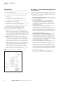
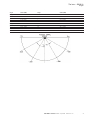
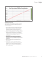
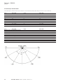
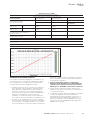
Directional Characteristics
SPL directional characteristics as measure in accordance with CAN/ULC-S525, measured on Tone 19.
Angle OSPL (dBA) Angle OSPL (dBA)
Short Flare Version Horizontal Axis
Reference (90º) 89.9 Reference (90ºC) 89.9
139 86.9 (-3 dBA) 46 86.9 (-3 dBA)
148 83.9 (-6 dBA) 35 83.9 (-6 dBA)
180 81.8 0º 81.5
Short Flare Version Vertical Axis
Reference (90º) 89.8 Reference (90º) 89.8
143 86.8 (- 3 dBA) 47 86.8 (-3 dBA)
150 83.8 (- 3 dBA) 35 83.8 (-6 dBA)
180 82.2 0º 81.2

7THE HORN – DB3B UL TM261 April 2020 www.eaton.com
The horn – DB3B UL
English
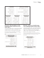
Angle OSPL (dBA) Angle OSPL (dBA)
Long Flare Version Horizontal Axis
Reference (90º) 93.9 Reference (90ºC) 93.9
165 90.9 (-3 dBA) 20 90.9 (-3 dBA)
* 87.9 (-6 dBA) * 87.9 (-6 dBA)
180 92.0 0º 91.9
Long Flare Version Vertical Axis
Reference (90º) 93.7 Reference (90º) 93.7
* 90.7 (- 3 dBA) 24 90.7 (-3 dBA)
* 87.7 (- 3 dBA) * 87.7 (-6 dBA)
180 91.9 0º 91.8

8 THE HORN – DB3B UL TM261 April 2020 www.eaton.com
The horn – DB3B UL
English
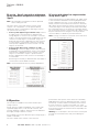
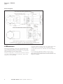
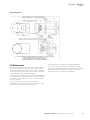
General arrangement
5.0 Maintenance
During the working life of the unit, it should require little
or no maintenance. GRP will resist attack by most acids,
alkalis and chemicals and is as resistant to concentrated
acids and alkalis as most metal products.
However, if abnormal or unusual environmental conditions
occur due to plant damage or accident etc., then visual
inspection is recommended.
If the unit requires cleaning, then only clean exterior with
a damp cloth to avoid electro-static charge build up.
If a unit fault should occur, then the unit can be repaired
by MEDC.
If you acquired a significant quantity of units, then it
is recommended that spares are also made available.
Please discuss your requirements with the Technical Sales
Engineers at MEDC.

9THE HORN – DB3B UL TM261 April 2020 www.eaton.com
The horn – DB3B UL
English
6.0 Certification/approvals
UL listed for use in USA (USL) and Canada (CNL) –
Audible signal applicance for fire alarm or general use.
Please refer to the marking on the unit for specific
approval details
(USL) Class I, Zone 1 AEx db IIC T*
Zone 21 AEx tb IIIC
(CNL) Class I, Zone 1 Ex db IIC Gb T*
Class II, Zone 21, Ex tb IIIC Db
Also suitable for: Class I, Div. 2 Groups A, B, C, D
Class II, Div. 2, Groups F & G
Class III, Div. 1
Applicable Standards:
(USL) UL 60079-0, Edition 7
UL 60079-1, Edition 7
ANSI/ISA 60079-31, Edition 2
UL 464, Edition 9
(CNL) CSA C22.2 No. 60079-0:19
CSA C22.2 No. 60079-1:16
CSA C22.2 No. 60079-31, Edition 2
CAN/ULC-S525-07
T-Ratings:
Max. Power rating T
amb.
T-ratings (T*)
15W
-67°F to +185°F (-55°C to +85°C) T4/T135°C
-67°F to +131°F (-55°C to +55°C) T5/T100°C
-67°F to +104°F (-55°C to +40°C) T6/T85°C
Electrical ratings:
The DB3B is available in a number of different input
voltage variations:
1. 12 V to 48 V dc, 716 mA to 171 mA, Special
Application *
2. 110 Vac, 50/60 Hz, 122mA, Special Applicaton.
3. 120 V ac, 50/60 Hz, 110 mA, Regulated.
4. 220/230/ Vac, 50/60 Hz, 63 mA, Special Application.
5. 240 Vac, 50/60 Hz, 58 mA, Regulated.
*Note: the DC special application version is suitable for
use with 24Vdc regulated supplies.
7.0 Special conditions for safe use
1. For replacement purposes the cover fixing screws
shall be of stainless steel grade A2-70 or stronger.
2. Painting and surface finishes, other than those applied
by the manufacturer, are not permitted.
3. When the unit is used in dust atmospheres the
cable entries used shall be sealed to maintain
the IP6X rating, in accordance with the applicable
installation codes.
4. Warning - Do not open when an explosive
atmosphere is present.
5. For supply connections, use minimum 105°C
rated wire.
6. Warning - On painted units, to avoid electrostatic
charge build up, clean enclosure with a damp cloth
7. Warning – to reduce the risk of ignition of hazardous
atmospheres, conduit openings must have a sealing
fitting connected within 50mm of the enclosure.
8. Warning - This product is not nonincendive. It is
a Zone 1 Ex d product. When used in a Division
2 application by equivalence, it must be installed
as a Zone 1 Ex d product to maintain the type of
protection.

10 THE HORN – DB3B UL TM261 April 2020 www.eaton.com
The horn – DB3B UL
English
8.0 Functional safety
Introduction
The DB3B Sounder has been designed for use
in potentially explosive atmospheres and harsh
environmental conditions. The glass reinforced polyester
enclosures are suitable for use offshore or onshore,
where light weight combined with corrosion resistance
is required.
The safety function of the Sounder is to provide a
pre-determined audible warning sound when required if
the correct voltage is applied to the unit. The DC version
of the Sounder is designed to operate on a supply voltage
between 12-48v dc.
Under No fault (Normal) Operating conditions the DB3B
Sounder will provide an audible warning sound when
required by the system.
Under fault conditions the failure mode of the Sounder
is a failure to provide an audible warning sound. For the
failure rate associated with this failure mode please refer
to the table below.
Assessment of functional safety
This Sounder is intended for use in a safety system
conforming to the requirements of IEC61508. UL has
conducted a Failure Modes Effect and Diagnostic Analysis
(FMEDA) of the DB3B Sounder against the requirements
of IEC 61508-2 using a Proof Test Interval of 8760hrs.
The results are shown below and are based on Route 1
H
.
The Sounder is classed as a Type B device.
DB3B Sounder
Safety Function of DB3B Sounder:
To provide a pre-described audible warning sound when required’
Summary of clauses
2/7.4.2 And 2/7.4.4
DB3B Sounder
Single mode (1oo1)
DB3B Sounder
Redundant mode (1oo2)
Verdict
Architectural constraints
Safe Failure Fraction (SFF)
HFT=0 HFT=1 Type B
65.9% 65.9% SIL 1(1oo1)
SIL 2 (1oo2)
Random hardware
failures: [h
-1
]
λ
DD
λ
DU
6.5E+09
1.16E-07
6.5E+10
1.16E-08
Random hardware
failures: [h
-1
]
λ
SD
λ
SU
0.00E+00
2.18E-07
0.00E+00
2.18E-08
PFD @ PTI = 8760Hrs
MTTR = 8 Hrs
5.09E-04 5.09E-05 SIL 3(1oo1)
Average freq. of dangerous failure (high
demand-PFH)[h
-1
]
1.16E-07 1.16E-08 SIL 2(1oo1)
Hardware safety integrity compliance Route 1
H
Systematic safety integrity compliance Route 1
s
Systematic Capability
(SC1, SC2, SC3, SC4)
SC2
Hardware safety integrity achieved Limited to: SIL 1 (1oo1) & SIL 2 (1oo2) due to SFF value.

11THE HORN – DB3B UL TM261 April 2020 www.eaton.com
The horn – DB3B UL
English
Conditions of safe use
The following conditions apply the installation, operation
and maintenance the assessed equipment. Failure to
observe these may compromise the safety integrity the
assessed equipment:
1. The user shall comply with the requirements given in
the manufacturer’s user documentation (This Safety
Manual and Technical manual) in regard all relevant
functional safety aspects such as application of use,
installation, operation, maintenance, proof tests,
maximum ratings, environmental conditions, repair, etc;
2. Selection of this equipment for use in safety functions
and the installation, configuration, overall validation,
maintenance and repair shall only be carried out by
competent personnel, observing all the manufacturer’s
conditions and recommendations in the user
documentation.
3. All information associated with any field failures of
this product should be collected under a dependability
management process (e.g., IEC 60300-2) and reported to the
manufacturer.
4. The unit should be tested at regular intervals to
identify any malfunctions; in accordance with this
safety manual.
5. If the product is used in a redundant installation,
both hardware safety integrity and systematic safety
integrity for SIL 2 can be achieved. The installation
must be such as to ensure sufficient protection
against common cause failures and independence
from cascading failures.

12
The horn – DB3B UL
Français
THE HORN – DB3B UL TM261 April 2020 www.eaton.com
Contents
1.0 INTRODUCTION .......................14
2.0 MESSAGES ET AVERTISSEMENTS DE SÉCURITÉ GÉNÉRALE . . . . . . . . . . . . . . . . . . . . . . . . . . . . . .14
3.0 INSTALLATION . . . . . . . . . . . . . . . . . . . . . . . . . . . . . . . . . . . . . . . . . . . . . . . . . . . . . . . . . . . . . . . . . . . . . .14
Accès aux bornes . . . . . . . . . . . . . . . . . . . . . . . . . . . . . . . . . . . . . . . . . . . . . . . . . . . . . . . . . . . . . . . . . . . . . . . . . . 14
Détails de câblage . . . . . . . . . . . . . . . . . . . . . . . . . . . . . . . . . . . . . . . . . . . . . . . . . . . . . . . . . . . . . . . . . . . . . . . . . . 15
Version CA, détails du câblage (types 1 et 2) . . . . . . . . . . . . . . . . . . . . . . . . . . . . . . . . . . . . . . . . . . . . . . . . . . . . . 15
Détails du câblage version CC – Trois étages sans surveillance (type 3) . . . . . . . . . . . . . . . . . . . . . . . . . . . . . . . . 15
Détails du câblage version CC – Double étage avec +VE commun et surveillance
(configuration standard) (type 4) . . . . . . . . . . . . . . . . . . . . . . . . . . . . . . . . . . . . . . . . . . . . . . . . . . . . . . . . . . . . . . 16
Version CC – Jusqu’à 3 étages sélectionnables par l’utilisateur avec 2
étages alimentés indépendamment (type 5) . . . . . . . . . . . . . . . . . . . . . . . . . . . . . . . . . . . . . . . . . . . . . . . . . . . . 16
Détails du câblage version CC – Jusqu’à trois étages avec ou sans surveillance
(configuration alternative) (type 6) . . . . . . . . . . . . . . . . . . . . . . . . . . . . . . . . . . . . . . . . . . . . . . . . . . . . . . . . . . . . .17
Détails de câblage de la version CC avec activation d’étage sans tension (type 7) . . . . . . . . . . . . . . . . . . . . . . . . .17
4.0 FONCTIONNEMENT . . . . . . . . . . . . . . . . . . . . . . . . . . . . . . . . . . . . . . . . . . . . . . . . . . . . . . . . . . . . . . . . .18
Caractéristiques directionnelles: . . . . . . . . . . . . . . . . . . . . . . . . . . . . . . . . . . . . . . . . . . . . . . . . . . . . . . . . . . . . . . . 18
5.0 MAINTENANCE . . . . . . . . . . . . . . . . . . . . . . . . . . . . . . . . . . . . . . . . . . . . . . . . . . . . . . . . . . . . . . . . . . . . .22
6.0 CERTIFICATION/ AUTORISATIONS . . . . . . . . . . . . . . . . . . . . . . . . . . . . . . . . . . . . . . . . . . . . . . . . . . . . .23
Caractéristiques électriques: . . . . . . . . . . . . . . . . . . . . . . . . . . . . . . . . . . . . . . . . . . . . . . . . . . . . . . . . . . . . . . . . . . 23
7.0 CONDITIONS SPÉCIALES POUR UNE UTILISATION SÛRE . . . . . . . . . . . . . . . . . . . . . . . . . . . . . . . . . .23
8.0 SÉCURITÉ FONCTIONNELLE . . . . . . . . . . . . . . . . . . . . . . . . . . . . . . . . . . . . . . . . . . . . . . . . . . . . . . . . . .23
Introduction . . . . . . . . . . . . . . . . . . . . . . . . . . . . . . . . . . . . . . . . . . . . . . . . . . . . . . . . . . . . . . . . . . . . . . . . . . . . . . . 23
Évaluation de sécurité fonctionnelle . . . . . . . . . . . . . . . . . . . . . . . . . . . . . . . . . . . . . . . . . . . . . . . . . . . . . . . . . . . . 23
Conditions d’utilisation sécurisée . . . . . . . . . . . . . . . . . . . . . . . . . . . . . . . . . . . . . . . . . . . . . . . . . . . . . . . . . . . . . . 24

13
The horn – DB3B UL
Français
THE HORN – DB3B UL TM261 April 2020 www.eaton.com
1.0 Introduction
Cette gamme de sounders, adaptée pour les alarmes
incendie ou d’utilisation générale, est conçue pour
une utilisation dans des atmosphères potentiellement
explosives de type gaz (G) ou gaz et poussière (GD).
Remarque: L’unité (G) a une sortie nominale plus élevée
de 6 dB que l’unité (GD).
Le boîtier est fabriqué à partir d’un polyester renforcé de
verre stable aux UV avec un sondeur en thermoplastique
robuste. Un support de montage en acier inoxydable, des
vis et fixations de couvercle sont incorporés tout au long,
assurant ainsi un produit sans corrosion.
Une version pour les emplacements ordinaires listés
UL est également disponible pour une utilisation en
atmosphères non explosives.
2.0 Messages et avertissements de
sécurité générale
Toutes les instructions et les messages de sécurité
dans ce manuel doivent être suivies pour permettre
l’installation sécuritaire de l’appareil. L’appareil ne doit être
installé et entretenu que par du personnel correctement
formé sur site/des installateurs.
I. Pour réduire le risque d’inflammation d’atmosphères
dangereuses et les chocs, ne pas brancher l’appareil
jusqu’à ce que l’installation a été achevée et que le
dispositif est entièrement étanche et sécurisé.
II. Pour réduire le risque d’inflammation d’atmosphères
dangereuses et les chocs, conservez l’appareil
hermétiquement fermé lorsque le circuit est sous
tension.
III. Avant de retirer le couvercle pour l’installation ou
l’entretien, veillez à ce l’appareil est débranché.
IV. Après l’installation, testez le dispositif pour assurer
un fonctionnement correct.
V. Après l’installation, s’assurer qu’une copie de ce
manuel est mis à la disposition de tout le personnel
d’exploitation.
VI. Lors de l’installation de l’appareil, les exigences pour
la sélection, l’installation et le fonctionnement doivent
se faire conformément aux règlements IEE de
câblage et du “National Electrical Code” en Amérique
du Nord. Des exigences nationales et/ou locales
supplémentaires peuvent s’appliquer.
VII. La connexion des câbles doit être conforme aux
spécifications s’appliquant à l’application requise.
MEDC recommande que tous les câbles et fils soient
correctement identifiés. Veuillez consulter le schéma
de câblage dans le manuel (ou diagramme séparé
fourni avec l’unité).
VIII. Ceci est un produit Ex d, pour cette raison, des
presse-étoupes antidéflagrants et des bouchons
d’arrêt correctement répertoriés ou certifiés doivent
être utilisés.
IX. S’assurer que seul les bouchons répertoriés correctsou
certifiés sont utilisés pour obturer les points d’entrée
des presse-étoupes inutilisés et quel’indice IP/NEMA
de l’unité est maintenu. MEDCrecommande l’utilisation
d’un produit d’étanchéité type HYLOMAR PL32 sur les
filets de tous les.
X. presse-étoupes et bouchons et/ou d’une rondelle
d’étanchéité appropriée afin de maintenir l’indice IP
de l’unité.
XI. La borne de terre interne
doit être utilisée pour
une mise à la terre de protection lorsque nécessaire.
Ne pas retirer la tresse de masse de la borne de
terre, quand elle existe.
Pour les unités avec entrées métriques ; la continuité
du presse-étoupe et la mise à la terre peuvent être
réalisés avec une plaque de masse externe en
option. Si la plaque externe est montée, un composé
d’étanchéité de filetage comme HYLOMAR PL32 doit
être employé pour maintenir la classification IP de
l’appareil.
XII. Lors de l’installation de l’appareil, MEDC
recommande l’utilisation d’éléments de fixation en
acier inoxydable. S’assurer que tous les écrous,
boulons et fixations sont sécurisés.
XIII. L’unité doit être positionnée de telle sorte que
les débris, la poussière ou l’eau ne puissent pas
s’installer dans la sondeur rentrante.
XIV. L’unité doit être positionnée, de telle sorte que tout
objet solide ne faisant pas partie de l’équipement,
soit au minimum à 40 mm du joint Ex d flamepath.
3.0 Installation
L’unité est montée au moyen de 2 trous de fixation hors
Ø23/64” (Ø9 mm) dans le support de montage/étrier en
forme d’U. Si nécessaire, l’unité peut être initialement
placée au moyen du trou central Ø33/64” (Ø13 mm) de
l’étrier. L’unité peut ensuite être tournée à la position
désirée et fixée au moyen des autres trous.
S’il est commandé avec l’unité, un support de montage
pivotant optionnel est disponible pour permette un plus
ample réglage rotationnel de l’unité.
Les trous de fixation ont été conçus pour accepter une vis
ou un boulon Ø5/16” (M8).
Accès aux bornes
Le couvercle est fixé avec 6 vis de couvercle M5 (4,0mm
A/F clé hexagonale). Une fois que les fixations du
couvercle sont dévissées, le couvercle peut être soulevé
de l’enceinte pour accéder à l’intérieur. Les fixations du
couvercle sont captives et resteront dans le couvercle.
Une fois que la fixation au bornier est terminée, replacez
soigneusement l’ensemble du couvercle sur le corps, en
évitant d’endommager les surfaces de contact. Serrez les
vis du couvercle uniformément. Assurez-vous que le joint
torique est correctement placé sur le couvercle pendant le
remontage. Assurez-vous que l’écart maximum requis de
0,0015” (0,038 mm) est maintenu entre le couvercle et le
corps du boîtier une fois assemblés.

14
The horn – DB3B UL
Français
THE HORN – DB3B UL TM261 April 2020 www.eaton.com
Détails de câblage
L’unité est disponible dans un certain nombre de
configurations de base :
1. Entrée CA, un seul étage.
2. Entrée CA, deux étages avec sélection d’étage sans
tension.
3. Entrée CC, jusqu’à 3 étages sélectionnables par
l’utilisateur sans surveillance.
4. Entrée CC, jusqu’à 2 étages sélectionnables par
l’utilisateur avec EOL/surveillance (configuration
standard).
5. Entrée CC, jusqu’à 3 étages sélectionnables par
l’utilisateur avec 2 étages alimentés indépendamment.
6. Entrée CC, jusqu’à 3 étages sélectionnables
par l’utilisateur avec EOL optionnel/surveillance
(configuration alternative).
7. Entrée CC, 5 étages sélectionnables par l’utilisateur
avec sélection d’étage sans tension avec ou sans
surveillance.
Version CA, détails du câblage (types 1 et 2)
• Type 1: Branchez les fils de phase et le neutre aux
bornes comme détaillé dans le schéma de câblage.
L’unité sera fournie avec un lien entre R1 et R0 monté
sur les bornes. Quand l’alimentation est appliquée à
l’unité, la tonalité de l’étage 1 sera produite comme
sélectionnée sur le commutateur DIP à 5 positions.
• Type 2: Branchez les fils de phase et le neutre aux
bornes comme détaillé dans le schéma de câblage.
L’unité sera fournie sans lien monté entre R1 et R0.
Branchez les fils et les interrupteurs de commande
à distance sur les bornes R0, R1 et R2, comme
indiqué. Lorsque l’alimentation est initialement
appliquée à l’unité, aucune tonalité ne sera produite.
Quand le commutateur connecté à R1 est fermé,
la tonalité de l’étage 1 sera produite comme
sélectionnée par le commutateur DIP à 5 positions
sur la platine. Quand le commutateur connecté à R2
est fermé, la tonalité présélectionnée pour l’étage 2
est produite. Voir le tableau tonalité 2 pour les détails
des tonalités présélectionnées.
Remarque : La fermeture des deux commutateurs ne
produira aucun son.
Détails du câblage version CC – Trois étages
sans surveillance (type 3)
Ce type peut être configuré de plusieurs manières
différentes en fonction des besoins. La sélection
indépendante des tonalités pour les trois étages se fait
au moyen de 3 des 5 commutateurs DIP montés sur la
platine :
• Système à deux fils (étage unique): Branchez les fils
d’alimentation positif et négatif aux bornes, comme
détaillé dans le schéma de câblage.
• Système à deux fils (double étage, polarité
inversée): Branchez les fils d’alimentation positif et
négatif aux bornes, comme détaillé dans le schéma de
câblage. Le second étage est produit en inversant la
polarité de l’alimentation de l’unité.
• Système à 3 fils (double étage, commun +VE):
Branchez les trois fils d’alimentation aux bornes
comme détaillé dans le schéma de câblage
(fil 1 commun +VE et 2 fils -VE). L’étage 1 est produit
lorsque l’alimentation est appliquée entre les bornes
+VE commun et -VE de l’étage 1. L’étage 2 est produit
lorsque l’alimentation est appliquée entre les bornes
+VE commun et -VE de l’étage 2.
• Système à 3 fils (double étage, commun -VE):
Branchez les trois fils d’alimentation aux bornes
comme détaillé dans le schéma de câblage (2 fils +VE
et 1 fil commun -VE). L’étage 1 est produit lorsque
l’alimentation est appliquée entre les bornes +VE de
l’étage 1 et -VE commun. L’étage 2 est produit lorsque
l’alimentation est appliquée entre les bornes +VE de
l’étage 2 et -VE commun d’étage.
• Système à 4 fils (triple étage, commun -VE): Branchez
les 4 fils d’alimentation aux bornes comme détaillé dans
le schéma de câblage (3 fils +VE et 1 fil commun -VE).
L’étage 1 est produit lorsque l’alimentation est appliquée
entre les bornes +VE de l’étage 1 et -VE commun.
L’étage 2 est produit lorsque l’alimentation est appliquée
entre les bornes +VE de l’étage 2 et -VE commun.
L’étage 3 est produit lorsque l’alimentation est appliquée
entre les bornes +VE de l’étage 3 et -VE commun.
Toutes les versions sont fournies avec des bornes
pour permettre des connexions de boucle entrée et
sortie pour les fils d’alimentation.

15
The horn – DB3B UL
Français
THE HORN – DB3B UL TM261 April 2020 www.eaton.com
Détails du câblage version CC – Double
étage avec +VE commun et surveillance
(configuration standard) (type 4)
Branchez jusqu’à 4 fils d’alimentation aux bornes comme
détaillé dans le schéma de câblage. L’étage 1 est produit
lorsque l’alimentation est appliquée entre les bornes
+VE commun et -VE de l’étage 1. L’étage 2 est produit
lorsque l’alimentation est appliquée entre les bornes +VE
commun et -VE de l’étage 2.
La fonctionnalité de surveillance est obtenue lorsque
l’alimentation est connectée entre les bornes M1 et M2.
Remarque: les bornes surveillées ne sont pas
dépendantes de la polarité.
Version CC – Jusqu’à 3 étages
sélectionnables par l’utilisateur avec 2
étages alimentés indépendamment (type 5)
Branchez jusqu’à 4 fils d’alimentation aux bornes comme
détaillé dans le schéma de câblage. L’étage 1 est produit
quand l’alimentation est appliquée entre les bornes de
l’étage 1. L’étage 2 est produit quand l’alimentation est
appliquée entre les bornes de l’étage 2. Les étages 1 et 2
peuvent être alimentés à partir de sources indépendantes.
L’étage 3 est produit lorsque l’alimentation est appliquée à
la fois aux bornes des étages 1 et 2.
Des résistances peuvent être ajoutées sur les
bornes, comme illustré, à des fins de surveillance. La
fonctionnalité de surveillance est disponible tout le temps,
si un relais de surveillance approprié est utilisé dans le
système.

16
The horn – DB3B UL
Français
THE HORN – DB3B UL TM261 April 2020 www.eaton.com
Détails du câblage version CC – Jusqu’à trois
étages avec ou sans surveillance (configuration
alternative) (type 6)
Remarque : Cette configuration alternative doit être
spécifiée à la commande de l’unité.
Ce type peut être connecté, soit à un commun des trois
étages, configuration -VE, soit si un EOL optionnel est
spécifié, il peut être configuré à un commun des deux
étages, configuration -VE avec surveillance.
• Système à 4 fils (triple étage, commun +VE) :
Branchez 4 fils d’alimentation aux bornes comme
détaillé dans le schéma de câblage (fil 1 commun
+VE et 3 fils -VE). L’étage 1 est produit lorsque
l’alimentation est appliquée entre les bornes +VE
commun et -VE de l’étage 1. L’étage 2 est produit
lorsque l’alimentation est appliquée entre les bornes
+VE commun et -VE de l’étage 2. L’étage 3 est produit
lorsque l’alimentation est appliquée entre les bornes
+VE commun et -VE de l’étage 3.
• Système à 4 fils (double étage, commun -VE
avec surveillance) : Branchez 4 fils d’alimentation
aux bornes comme détaillé dans le schéma de
câblage. L’étage 1 est produit quand l’alimentation est
appliquée entre les bornes du commun -VE et +VE de
l’étage 1. L’étage 2 est produit quand l’alimentation est
appliquée entre les bornes du commun -VE et +VE de
l’étage 2.
La fonctionnalité de surveillance est obtenue lorsque
l’alimentation est connectée entre les bornes M1
et M2.
Remarque : les bornes surveillées ne sont pas
dépendantes de la polarité.
Détails de câblage de la version CC avec
activation d’étage sans tension (type 7)
Branchez les fils d’alimentation positif (+VE) et négatif
(-VE) aux bornes, comme indiqué dans le schéma de
câblage. Quand l’alimentation est appliquée à l’unité,
aucune tonalité ne sera produite initialement. Branchez
les fils et les interrupteurs de commande à distance
sur les bornes R0 à R5, comme indiqué. Quand le
commutateur connecté à R1 est fermé, la tonalité de
l’étage 1 sera produite comme sélectionnée par le
commutateur DIP à 5 positions sur la platine. Quand l’un
des autres commutateurs connectés de R2 à R5 est
fermé, la tonalité présélectionnée pour les étages 2 à 5
est produite. Voir le tableau tonalité 2 pour les détails des
tonalités présélectionnées.
Remarque: La fermeture de plus d’un commutateur à la
fois ne produira aucune tonalité.
La page est en cours de chargement...
La page est en cours de chargement...
La page est en cours de chargement...
La page est en cours de chargement...
La page est en cours de chargement...
La page est en cours de chargement...
La page est en cours de chargement...
La page est en cours de chargement...
-
 1
1
-
 2
2
-
 3
3
-
 4
4
-
 5
5
-
 6
6
-
 7
7
-
 8
8
-
 9
9
-
 10
10
-
 11
11
-
 12
12
-
 13
13
-
 14
14
-
 15
15
-
 16
16
-
 17
17
-
 18
18
-
 19
19
-
 20
20
-
 21
21
-
 22
22
-
 23
23
-
 24
24
-
 25
25
-
 26
26
-
 27
27
-
 28
28


MEDC DB3B Tehcnical Le manuel du propriétaire
- Taper
- Le manuel du propriétaire
- Ce manuel convient également à
dans d''autres langues
- English: MEDC DB3B Tehcnical Owner's manual
Documents connexes
Autres documents
-
Eaton DB3B Technical Manual
-
Eaton MEDC BG2 Exe Technical Manual
-
EZVIZ Беспроводной датчик протечки воды T10 (CS-Т10-A) Manuel utilisateur
-
Klein Tools M2O41537KIT Manuel utilisateur
-
Klein Tools VDV500-063 Manuel utilisateur
-
 Klaxon Nexus 120 AC Manuel utilisateur
-
McQuay 110 AC Manuel utilisateur
-
Gentex WGESA24 Series Manuel utilisateur
-
Simplicity 076153-02 Manuel utilisateur
-
