
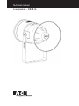
Loudspeaker – DB4B UL
Technical manual

ii LOUDSPEAKER – DB4B UL TM262 April 2020 www.eaton.com
DISCLAIMER OF WARRANTIES AND LIMITATION OF LIABILITY
The information, recommendations, descriptions and safety notations in this document are based on Eaton Corporation’s
(“Eaton”) experience and judgment and may not cover all contingencies. If further information is required, an Eaton sales
office should be consulted. Sale of the product shown in this literature is subject to the terms and conditions outlined in
appropriate Eaton selling policies or other contractual agreement between Eaton and the purchaser.
THERE ARE NO UNDERSTANDINGS, AGREEMENTS, WARRANTIES, EXPRESSED OR IMPLIED, INCLUDING
WARRANTIES OF FITNESS FOR A PARTICULAR PURPOSE OR MERCHANTABILITY, OTHER THAN THOSE
SPECIFICALLY SET OUT IN ANY EXISTING CONTRACT BETWEEN THE PARTIES. ANY SUCH CONTRACT STATES THE
ENTIRE OBLIGATION OF EATON. THE CONTENTS OF THIS DOCUMENT SHALL NOT BECOME PART OF OR MODIFY
ANY CONTRACT BETWEEN THE PARTIES.
In no event will Eaton be responsible to the purchaser or user in contract, in tort (including negligence), strict liability or
other-wise for any special, indirect, incidental or consequential damage or loss whatsoever, including but not limited to
damage or loss of use of equipment, plant or power system, cost of capital, loss of power, additional expenses in the
use of existing power facilities, or claims against the purchaser or user by its customers resulting from the use of the
information, recommendations and descriptions contained herein. The information contained in this manual is subject to
change without notice.

iiiLOUDSPEAKER – DB4B UL TM262 April 2020 www.eaton.com
Loudspeaker – DB4B UL
English
Contents
1.0 INTRODUCTION ........................1
2.0 GENERAL SAFETY MESSAGES AND WARNINGS ...................1
3.0 INSTALLATION .......................................................................1
Access to terminals .......................................................................... 1
4.0 OPERATION .........................................................................2
5.0 MAINTENANCE ......................................................................3
6.0 CERTIFICATION/APPROVALS ...........................................................4
T-Ratings .................................................................................. 4
7.0 SPECIAL CONDITIONS FOR SAFE USE ...................................................4
8.0 FUNCTIONAL SAFETY ................................................................4
Introduction ..............................4

iv LOUDSPEAKER – DB4B UL TM262 April 2020 www.eaton.com

1
Loudspeaker – DB4B UL
English
LOUDSPEAKER – DB4B UL TM262 April 2020 www.eaton.com
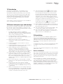
1.0 Introduction
This range of loudspeakers, is intended for use in
potentially explosive gas (G) or gas and dust (GD)
atmospheres and has a power rating of up to 25 watts.
The enclosure is manufactured from a UV stable glass
reinforced polyester with a rugged thermoplastic flare.
Stainless steel mounting bracket, cover screws and
fixings are incorporated throughout thus ensuring a
corrosion free product.
A UL ordinary locations listed version is also available for
use in non-explosive atmospheres.
2.0 General safety messages and warnings
All instructions and safety messages in this manual must
be followed to allow safe installation of the device. The
device must only be installed and maintained by correctly
trained site personnel/installers.
I. To reduce the risk of ignition of hazardous
atmospheres and shock, do not apply power to the
device until installation has been completed and the
device is fully sealed and secured.
II. To reduce the risk of ignition of hazardous
atmospheres and shock, keep device tightly closed
when the circuit is energised.
III. Before removing the cover for installation or
maintenance, ensure that the power to the device
is isolated.
IV. Following installation, test the device to ensure
correct operation.
V. Following installation ensure a copy of this manual is
made available to all operating personnel.
VI. When installing the device, requirements for
selection, installation and operation should be
referred to e.g. IEE Wiring Regulations and the
‘National Electrical Code’ in North America. Additional
national and/or local requirements may also apply.
VII. Cable termination should be in accordance with the
specification applying to the required application.
MEDC recommends that all cables and cores should
be correctly identified. Please refer to the wiring
diagram in this manual (or separate diagram provided
with the unit).
VIII. This is an Ex d product, correctly listed or certified
explosion proof cable glands and stopping plugs must
be used.
IX. Ensure that only the correct listed or certified
stopping plugs are used to blank off unused gland
entry points and that the NEMA/IP rating of the unit
is maintained.
X. MEDC recommend the use of a sealing compound
such as HYLOMAR PL32 on the threads of all glands
and stopping plugs and/or a suitable sealing washer
in order to maintain the IP rating of the unit.
XI. The internal earth terminal
must be used for
protective earthing when required. Do not remove
the internal ground strap from the earth terminal.
For units with metric entries; gland continuity and
earthing my be achieved with an optional external
earth plate. If the external plate is fitted, a thread
sealing compound such as HYLOMAR PL32 must be
employed to maintain the IP rating of the unit.
An additional internal stud is provided for a noiseless
(clean) earth connection
An additional internal stud is provided for a noiseless
where local codes or
authorities permit or require such a connection.
XII. When installing the device, MEDC recommends the
use of stainless steel fasteners. Ensure that all nuts,
bolts and fixings are secure.
XIII. The unit should be positioned such that debris, dust
or water cannot settle in the re-entrant horn.
XIV. The unit should be positioned such that any solid
object, not part of the equipment, is a minimum of
40mm from the Ex d flamepath joint.
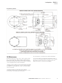
3.0 Installation
The unit is mounted via 2 off Ø23/64” (Ø9mm) fixing
holes in the U-shaped stirrup/mounting bracket. If
required, the unit can be initially placed via the Ø33/64”
(Ø13mm) central hole in the stirrup. The unit can then
be rotated to the required position and fixed via the
other holes.
If ordered with the unit, a swivel mounting bracket option
is available to allow further rotational adjustment to
the unit.
The fixing holes have been designed to accept an Ø5/16”
(M8) screw or bolt.
Access to terminals
The cover is secured with 6 off M5 cover screws (4.0mm
A/F hexagon key). Once the cover fixings are unscrewed,
the cover can be lifted away from the enclosure to gain
access to the interior. The cover fixings are captive and
will remain in the cover.
Once termination is complete, carefully replace the
cover assembly back onto the body, avoiding damage to
the mating surfaces. Tighten the cover screws evenly.
Ensure three O-ring is seated correctly on the cover
during re-assembly. Ensure the required maximum gap of
0.00015” (0.0038mm) is maintained between the cover
and the enclosure body once assembled.

2 LOUDSPEAKER – DB4B UL TM262 April 2020 www.eaton.com
Loudspeaker – DB4B UL
English
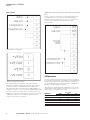
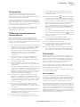
Wiring details
DB4B STANDARD 70V LINE WIRING
DB4B DIRECT CONNECTION (8Ω) WIRING
For standard 70V line units (Note: units with other line
voltages are available if specified when ordering), connect
power conections to numbered terminals to obtain the
required power rating (see section 4 for tapping table). For
loop-out connections, use second set of numbered terminals.
For direct connection 8 Ohm units, connect power from
amplifier to terminals as detailed, taking note of maximum
loudspeaker rating. Use second pair of terminals for
loop-out connections as required.
DB4B 100V/70V/25V LINE WITH OPTIONAL CAP AND/OR
PPTC
Connect 70V line connections to terminals marked ‘line’
on PCB, looping-out as required. Use supplied flying
lead along with common loop-in, loop-out connections
to select required power level (see section 4 for
tapping table).
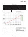
4.0 Operation
The line voltage and power rating of the unit is stated on
the unit label. The speaker is available in 3 standard power
ratings from 8 watts to 25 watts. Different sound levels
can be obtained by selecting the transformer tappings in
the unit. See table below for details.
Alternatively if requested when ordered, the unit can be
supplied with a direct 8Ohm connection to the driver for
connecting to a suitable audio source.
Transformer
tappings
Power (W)
25W 15W 8W
1:2 25.0 15.0 8.0
2:3 12.5 7.5 4.0
3:4 6.0 5.0 2.0
1:3 4.0 4.0 1.5
2:4 2.0 2.0 0.7
1:4 1.0 0.8 0.4

3LOUDSPEAKER – DB4B UL TM262 April 2020 www.eaton.com
Loudspeaker – DB4B UL
English
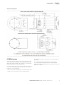
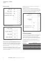
General arrangement
5.0 Maintenance
During the working life of the unit, it should require little
or no maintenance. GRP will resist attack by most acids,
alkalis and chemicals and is as resistant to concentrated
acids and alkalis as most metal products.
However, if abnormal or unusual environmental conditions
occur due to plant damage or accident etc., then visual
inspection is recommended.
If the unit requires cleaning, then only clean exterior with
a damp cloth to avoid electro-static charge build up.
If a unit fault should occur, then the unit can be repaired
by MEDC.
If you acquired a significant quantity of units, then it
is recommended that spares are also made available.
Please discuss your requirements with the Technical Sales
Engineers at MEDC.

4 LOUDSPEAKER – DB4B UL TM262 April 2020 www.eaton.com
Loudspeaker – DB4B UL
English
6.0 Certification/approvals
UL listed for use in USA (USL) and Canada (CNL)
Please refer to the marking on the unit for specific
approval details
(USL) Class I, Zone 1 AEx db IIC T*
Zone 21 AEx tb IIIC
(CNL) Class I, Zone 1 Ex db IIC Gb T*
Class II, Zone 21 Ex tb IIIC Db
Also suitable for:
Class I, Div. 2 Groups A, B, C, D
Class II, Div. 2, Groups F & G
Class III, Div. 1
Appliccable Standards:
(USL) UL 60079-0, Edition 7
UL 60079-1, Edition 7
ANSI/ISA 60079-31, Edition 2
UL- 1480
(CNL) CSA C22.2 No. 60079-0:11
CSA C22.2 No. 60079-1:11
CSA C22.2 No. 60079-31, Edition 2
CSA C22.2 No. 205-12
T-Ratings
Max. Power rating T
amb.
T-ratings (T*)
-67°F to +185°F (-55°C to +85°C) T4/T135°C
8W -67°F to +131° F (-55°C to +55°C) T5/ T100°C
-67°F to +104°F (-55°C to +40°C) T6/T85°C
-67°F to +185°F (-55°C to +85°C) T3/T200°C
15W -67°F to +158°F (-55°C to +70°C) T4/T135°C
-67°F to +104°F (-55°C to +40°C) T5/ T100°C
25W
-67°F to +158°F (-55°C to +70°C) T4/T135°C
-67°F to +104°F (-55°C to +40°C) T5/ T100°C
7.0 Special conditions for safe use
1. For replacement purposes the cover fixing screws
shall be of stainless steel grade A2-70 or stronger.
2. Painting and surface finishes, other than those applied
by the manufacturer, are not permitted.
3. When the unit is used in dust atmospheres the
cable entries used shall be sealed to maintain
the IP6X rating, in accordance with the applicable
installation codes.
4. Warning – Do not open when an explosive
atmosphere is present.
5. For supply connections, use minimum 105°C
rated wire.
6. Warning – to avoid electrostatic charge build up, clean
enclosure with a damp cloth.
7. Warning – to reduce the risk of ignition of hazardous
atmospheres, conduit openings must have a sealing
fitting connected within 50mm of the enclosure.
8. Warning - This product is not nonincendive. It is
a Zone 1 Ex d product. When used in a Division
2 application by equivalence, it must be installed
as a Zone 1 Ex d product to maintain the type of
protection.
8.0 Functional safety
Introduction
The DB4B Loudspeaker has been designed for use in
potentially explosive atmospheres and harsh environmental
conditions. The glass reinforced polyester enclosures are
suitable for use offshore or onshore, where light weight
combined with corrosion resistance is required.
The safety function of the Speaker is to provide an audible
warning when required.
Under No fault (Normal) Operating conditions the
DB4B Speaker will provide an audible warning sound
when required by the system.
Under fault conditions the failure mode of the Speaker
is a failure to provide an audible warning sound. For the
failure rate associated with this failure mode please refer
to the table below.
Assessment of functional safety
This Loudspeaker is intended for use in a safety system
conforming to the requirements of IEC61508.
UL has conducted a Failure Modes Effect and Diagnostic
Analysis (FMEDA) of the DB4B Loudspeaker against the
requirements of IEC 61508-2 using a Proof Test Interval
of 8760hrs.
The results are shown right and are based on Route 1
H
.
The Speaker is classed as a Type A device.

5LOUDSPEAKER – DB4B UL TM262 April 2020 www.eaton.com
Loudspeaker – DB4B UL
English
DB4B Speaker
Safety function of the DB4B speaker:
‘To raise an audible warning sound when required
Architectural constraints: Type A
HFT=0
SFF= 71.5%
Proof Test Interval
=8760Hrs
MTTR = 8 Hrs
SIL2
Random hardware failures: λ
DD
= 0
λ
DU
= 2.88E-08
λ
SD
= 0
λ
SU
= 7.22E- 0 8
Probability of failure on demand: PFD
AVG
=1.26E-04
(Low Demand Mode)
SIL3
Probability of Dangerous failure on safety function: PFH = 2.88E-08
(High Demand Mode)
SIL3
Hardware safety integrity compliance
[1]
Route 1
H
Systematic safety integrity compliance Route 1
S
Systematic Capability SC2
Overall SIL-capability achieved SIL 2 (Low Demand)*
SIL 2 (High Demand)*
*Limited to SIL 2 due to SFF value
Conditions of safe use
The following conditions apply to the istallation, operation
and maintenance of the assessed equipment. Failure to
observe these may may compromise the safety integrity
of the assessed equipment:
1. The user shall comply with the requirement given
in the manufacture’s user documentation (This
safety Manual and Technical manual) in regard to all
relevant functional safety aspects such as application
of use, installation, operation, maintenance, proof
tests, maximum ratings, environmental conditions,
repair, etc;
2. Selection of this equipment for use in safety
functions and the installation, configuration, overall
validation, maintenance and repair shall only be
carried out by competent personnel, observing all the
manufacturer’s conditions and recommendations in
the user documentation.
3. All informations associated with any field failures
of this product should be collected under a
dependability management process (e.g., IEC
60300-3-2) and reported to the manufacturer.
4. The unit should be tested at regular intervals to
identify any malfunctions; in accordance with this
safety manual.

6 LOUDSPEAKER – DB4B UL TM262 April 2020 www.eaton.com
Loudspeaker – DB4B UL
Francais
Contents
1.0 INTRODUCTION . . . . . . . . . . . . . . . . . . . . . . . . . . . . . . . . . . . . . . . . . . . . . . . . . . . . . . . . . . . . . . . . . . . . . .7
2.0 MESSAGES ET AVERTISSEMENTS DE SÉCURITÉ GÉNÉRALE . . . . . . . . . . . . . . . . . . . . . . . . . . . . . . .7
3.0 INSTALLATION .......................................................................7
Accès aux bornes ........................................................................... 7
4.0 FONCTIONNEMENT ..................................................................8
5.0 MAINTENANCE ......................................................................9
6.0 CERTIFICATION/AUTORISATIONS ......................................................10
T-nominale ................................................................................ 10
7.0 CONDITIONS SPÉCIALES POUR UNE UTILISATION SÛRE ..................................10
8.0 SÉCURITÉ FONCTIONNELLE ..........................................................10
Introduction ............................................................................... 10

7LOUDSPEAKER – DB4B UL TM262 April 2020 www.eaton.com
Loudspeaker – DB4B UL
Francais
1.0 Introduction
Cette gamme de haut-parleurs est destinée à une
utilisation dans des atmosphères potentiellement
explosives de gaz (G) ou de gaz et de poussière (GD) et a
une puissance nominale de 25 watts.
Le boîtier est fabriqué à partir d’un polyester renforcé de
verre stable aux UV avec un cornet en thermoplastique
robuste. Un support de montage en acier inoxydable, des
vis et fixations de couvercle sont incorporés tout au long,
assurant ainsi un produit sans corrosion.
Une version pour les emplacements ordinaires listés
UL est également disponible pour une utilisation en
atmosphères non explosives.
2.0 Messages et avertissements de
sécurité générale
Toutes les instructions et les messages de sécurité
dans ce manuel doivent être suivies pour permettre
l’installation sécuritaire de l’appareil. L’appareil ne doit être
installé et entretenu que par du personnel correctement
formé sur site / des installateurs.
I. Pour réduire le risque d’inflammation d’atmosphères
dangereuses et les chocs, ne pas brancher l’appareil
jusqu’à ce que l’installation a été achevée et que le
dispositif est entièrement étanche et sécurisé.
II. Pour réduire le risque d’inflammation d’atmosphères
dangereuses et les chocs, conservez l’appareil
hermétiquement fermé lorsque le circuit est
sous tension.
III. Avant de retirer le couvercle pour l’installation ou
l’entretien, veillez à ce l’appareil est débranché.
IV. Après l’installation, testez le dispositif pour assurer
un fonctionnement correct.
V. Après l’installation, s’assurer qu’une copie de ce
manuel est mis à la disposition de tout le personnel
d’exploitation.
VI. Lors de l’installation de l’appareil, les exigences pour
la sélection, l’installation et le fonctionnement doivent
se faire conformément aux règlements IEE de
câblage et du “National Electrical Code” en Amérique
du Nord. Des exigences nationales et / ou locales
supplémentaires peuvent s’appliquer.
VII. La connexion des câbles doit être conforme aux
spécifications s’appliquant à l’application requise.
MEDC recommande que tous les câbles et fils soient
correctement identifiés. Veuillez consulter le schéma
de câblage dans le manuel (ou diagramme séparé
fourni avec l’unité).
VIII. Ceci est un produit Ex d, pour cette raison, des
presse-étoupes antidéflagrants et des bouchons
d’arrêt correctement répertoriés ou certifiés doivent
être utilisés.
IX. S’assurer que seul les bouchons répertoriés corrects
ou certifiés sont utilisés pour obturer les points
d’entrée des presse-étoupes inutilisés et que l’indice
IP/NEMA de l’unité est maintenu.
X. MEDC recommande l’utilisation d’un produit
d’étanchéité type HYLOMAR PL32 sur les filets de
tous les presse-étoupes et bouchons et/ou d’une
rondelle d’étanchéité appropriée afin de maintenir
l’indice IP de l’unité.
XI. La borne de terre interne
doit être utilisée pour
une mise à la terre de protection lorsque nécessaire.
Ne pas retirer la tresse de masse de la borne de terre.
Pour les unités avec entrées métriques ; la continuité
du presse-étoupe et la mise à la terre peuvent être
réalisés avec une plaque de masse externe en
option. Si la plaque externe est montée, un composé
d’étanchéité de filetage comme HYLOMAR PL32
doit être employé pour maintenir la classification IP
de l’appareil.
Une tige interne supplémentaire est fournie pour une
connexion de terre sans bruit (propre)
Une tige interne supplémentaire est fournie pour une
là où les
codes locaux ou les autorités autorisent ou requièrent
une telle connexion.
XII. Lors de l’installation de l’appareil, MEDC
recommande l’utilisation d’éléments de fixation en
acier inoxydable. S’assurer que tous les écrous,
boulons et fixations sont sécurisés.
XIII. L’unité doit être positionnée de telle sorte que
les débris, la poussière ou l’eau ne puissent pas
s’installer dans la corne rentrante.
XIV. L’unité doit être positionnée, de telle sorte que tout
objet solide ne faisant pas partie de l’équipement,
soit au minimum à 40 mm du joint Ex d flamepath.
3.0 Installation
L’unité est montée au moyen de 2 trous de fixation hors
Ø23/64” (Ø9 mm) dans le support de montage/étrier en
forme d’U. Si nécessaire, l’unité peut être initialement
placée au moyen du trou central Ø33/64” (Ø13 mm) de
l’étrier. L’unité peut ensuite être tournée à la position
désirée et fixée au moyen des autres trous.
S’il est commandé avec l’unité, un support de montage
pivotant optionnel est disponible pour permette un plus
ample réglage rotationnel de l’unité.
Les trous de fixation ont été conçus pour accepter une vis
ou un boulon Ø5/16” (M8).
Accès aux bornes
Le couvercle est fixé avec 6 vis de couvercle M5
(4,0 mm A/F clé hexagonale). Une fois que les fixations du
couvercle sont dévissées, le couvercle peut être soulevé
de l’enceinte pour accéder à l’intérieur. Les fixations du
couvercle sont captives et resteront dans le couvercle.
Une fois que la fixation au bornier est terminée, replacez
soigneusement l’ensemble du couvercle sur le corps, en
évitant d’endommager les surfaces de contact. Serrez les
vis du couvercle uniformément. Assurez-vous que le joint
torique est correctement placé sur le couvercle pendant le
remontage. Assurez-vous que l’écart maximum requis de
0,0015” (0,038 mm) est maintenu entre le couvercle et le
corps du boîtier une fois assemblés.

8 LOUDSPEAKER – DB4B UL TM262 April 2020 www.eaton.com
Loudspeaker – DB4B UL
Francais
Détails de câblage
DB4B STANDARD 70 V CÂBLAGE DE LIGNE
DB4B CÂBLAGE CONNEXION DIRECTE (8Ω)
Pour les lignes de 70 V standard (Remarque: des unités avec
d’autres tensions de lignes sont disponibles si elles sont
spécifiées lors de la commande), branchez les connexions
électriques aux bornes numérotées pour obtenir la puissance
nécessaire voir la section 4 pour le tableau de taraudage).
Pour les boucles de connexion, utilisez le second jeu de
bornes numérotées.
Pour les connexions directes à 8 Ohm, connectez
l’alimentation de l’amplificateur aux bornes comme détaillé,
en prenant note de la puissance maximale du haut-parleur.
Utilisez une seconde paire de bornes pour les boucles de
connexion si nécessaire.
DB4B 100 V/70 V/25 V LIGNE AVEC CAPUCHON EN
OPTION ET/OU PPTC
Branchez les connexions de ligne 70 V aux bornes
marquées “ ligne “ sur la carte de circuit imprimé, avec
une boucle de sortie si nécessaire. Utilisez le câble volant
fourni avec les connexions communes de boucles entrée,
sortie pour sélectionner le niveau de puissance requis
(voir section 4 pour tableau de taraudage).
4.0 Fonctionnement
La tension de la ligne et la puissance nominale de l’unité
sont inscrites sur l’étiquette de l’unité. Le haut-parleur est
disponible en standard en 3 puissances de 8 watts à
25 watts. Différents niveaux sonores peuvent être
obtenues en sélectionnant le piquage du transformateur
dans l’unité. Voir tableau ci-dessous pour plus de détails.
De manière alternative, si cela était demandé à la
commande, l’unité peut être fournie avec une connexion
directe de 8 Ohm au pilote pour connecter une source
audio appropriée.
Piquages du
transformateur
Puissance (W)
25 W 15 W 8 W
1:2 25,0 15,0 8,0
2:3 12,5 7,5 4,0
3:4 6,0 5,0 2,0
1:3 4,0 4,0 1,5
2:4 2,0 2,0 0,7
1:4 1,0 0,8 0,4

9LOUDSPEAKER – DB4B UL TM262 April 2020 www.eaton.com
Loudspeaker – DB4B UL
Francais
Disposition générale
POS. 1
POS. 3
POS. 2
5.0 Maintenance
Pendant la durée de vie de l’unité, celle-ci devrait exiger
peu ou pas d’entretien. GRP résistera à l’attaque de la
plupart des acides, des alcalis et des produits chimiques
et est aussi résistant aux acides et aux alcalis concentrés
comme la plupart des produits métalliques.
Toutefois, si des conditions environnementales anormales
ou inhabituelles se produisent en raison de dommages à
l’installation ou d’accident, etc., alors un contrôle visuel
est recommandé.
Si l’unité nécessite un nettoyage, alors nettoyer
seulement l’extérieur avec un chiffon humide pour éviter
l’accumulation de charges électrostatiques.
En cas de panne, l’unité peut être réparée par MEDC.
Si vous avez acquis une importante quantité d’unités, il
est alors recommandé de prévoir des pièces de rechange
disponibles. Veuillez discuter de vos besoins avec les
ingénieurs technico-commerciaux de MEDC.

10 LOUDSPEAKER – DB4B UL TM262 April 2020 www.eaton.com
Loudspeaker – DB4B UL
Francais
6.0 Certification/autorisations
Listé UL pour utilisation aux USA (USL) et Canada (CNL)
Veuillez vous référer au marquage sur l’unité pour plus de
détails des approbations spécifiques
(USL) Class I, Zone 1 AEx db IIC T*
Zone 21 AEx tb IIIC
(CNL) Class I, Zone 1 Ex db IIC Gb T*
Class II, Zone 21 Ex tb IIIC Db
Convient également pour :
Class I, Div. 2 Groups A, B, C, D
Class II, Div. 2, Groups F & G
Class III, Div. 1
Normes applicables :
(USL) UL 60079-0, Edition 7
UL 60079-1, Edition 7
ANSI/ISA 60079-31, Edition 2
UL- 1480
(CNL) CSA C22.2 No. 60079-0:11
CSA C22.2 No. 60079-1:11
CSA C22.2 No. 60079-31, Edition 2
CSA C22.2 No. 205-12
T-nominale
Puissance max.
nominale T
amb.
T-nominale
(T*)
-67 °F à +185 °F (-55 °C à +85 °C) T4/T135 °C
8W -67 °F à +131 °F (-55 °C à +55 °C) T5/T100 °C
-67 °F à +104 °F (-55 °C à +40 °C) T6/T85 °C
-67 °F à +185 °F (-55 °C à +85 °C) T3/T200°C
15W -67 °F à +158 °F (-55 °C à +70 °C) T4/T135 °C
-67 °F à +104 °F (-55 °C à +40 °C) T5/T100 °C
25W
-67 °F à +158 °F (-55 °C à +70 °C) T4/T135 °C
-67 °F à +104 °F (-55 °C à +40 °C) T5/T100 °C
7.0 Conditions spéciales pour une
utilisation sûre
1. En cas de remplacement, les vis de fixation du couvercle
seront en acier inoxydable de grade A2-70 ou plus.
2. La peinture et la finition des surfaces, différentes
de celles appliquées par le fabricant, ne sont
pas autorisées.
3. Quand l’unité est utilisée dans une atmosphère
poussiéreuse, les entrées de câbles utilisées doivent
être scellées afin de maintenir l’indice IP6X suivant les
codes d’installation applicables.
4. Avertissement – Ne pas ouvrir quand une atmosphère
explosive est présente.
5. Pour des connexions d’alimentation, utilisez au
minimum des câbles classés 105 °C.
6. Avertissement – pour éviter l’accumulation de
charges électrostatiques, nettoyez le boîtier avec un
chiffon humide.
7. Avertissement – afin de réduire le risque
d’inflammation des atmosphères dangereuses, les
ouvertures de conduits doivent avoir un raccord
étanche relié à 50mm de l’enceinte.
8. Avertissement – Ce produit n’est pas non incendiaire.
Il s’agit d’un produit Zone 1 Ex d. Lorsqu’il est utilisé
dans une application de division 2 par équivalence, il
doit être installé en tant que produit Zone 1 Ex d pour
maintenir le type de protection.
8.0 Sécurité fonctionnelle
Introduction
Le haut-parleur DB4B a été conçu pour être utilisé dans
des atmosphères potentiellement explosives et des
conditions environnementales sévères. Les boîtiers en
polyester renforcé de fibres de verre sont adaptés à une
utilisation off-shore ou on-shore, où un poids léger et un
haut niveau de résistance à la corrosion sont nécessaires.
La fonction de sécurité du diffuseur sonore est de fournir
un avertissement sonore lorsque nécessaire.
Dans des conditions de fonctionnement sans défaillance
(normales), le haut-parleur DB4B émet un avertissement
sonore sur demande du système.
En cas de panne/défaillance, le mode de panne du
haut-parleur est indiqué par l’échec de l’émission de
l’avertissement sonore. Pour de plus amples détails sur le
taux d’échec/défaillance associé à ce mode de panne, voir
le tableau ci-dessous.
Évaluation de sécurité fonctionnelle
Ce haut-parleur est destiné à être utilisé dans un système
de sécurité conforme aux exigences IEC61508.
UL a procédé à une étude «Effet des modes de panne
et analyse du diagnostic» (Failure Modes Effect and
Diagnostic Analysis: FMEDA) sur le haut-parleur DB4B
par rapport aux exigences IEC 61508-2, avec un intervalle
entre essais de sûreté de 8760 heures.
Les résultats sont présentés à droite et sont basés sur la
Route 1
H
.
Le haut-parleur a été classé comme appareil de type A.

11LOUDSPEAKER – DB4B UL TM262 April 2020 www.eaton.com
Loudspeaker – DB4B UL
Francais
haut-parleur DB4B
Fonction de sécurité du diffuseur sonore DB4B :
« Émettre un avertissement sonore lorsque nécessaire »
Contraintes architecturales : Type A
HFT = 0
SFF = 71,5 %
Intervalle entre essais de sûreté
= 8 760 heures
MTTR (moyenne des temps techniques de réparation)
= 8 heures
SIL2
Défaillances de matériel aléatoires : λ
DD
= 0
λ
DU
= 2,88E-08
λ
SD
= 0
λ
SU
= 7, 2 2E- 0 8
Probabilité de défaillance sur demande : PFD
AVG
=1,26E-04
(mode demande faible)
SIL3
Probabilité de défaillance dangereuse sur
fonction de sécurité :
PFH = 2,88E-08
(mode demande élevée)
SIL3
Conformité d'intégrité de sécurité du matériel
[1]
Route 1
H
Conformité d'intégrité de sécurité systématique Route 1
S
Capacité systématique SC2
Capacité SIL globale atteinte SIL 2 (demande faible)*
SIL 2 (demande élevée)*
*Limitée à SIL 2 en raison de la valeur SFF
Conditions d’utilisation sécurisée
Les conditions suivantes s’appliquent à l’installation, au
fonctionnement et à l’entretien de l’équipement évalué.
Le non-respect de ces conditions peut compromettre
l’intégrité de sécurité de l’équipement évalué :
1. L’utilisateur est tenu de se conformer aux exigences
énoncées dans la documentation utilisateur fournie
par le fabricant (ce Manuel de sécurité et Manuel
technique) concernant tous les aspects appropriés
de fonctionnement sécurisé, tels que les applications
d’utilisation, l’installation, le fonctionnement,
l’entretien, les essais de sûreté, les taux maximum,
les conditions environnementales, les réparations, etc.
2. Le choix de cet équipement en vue d’une utilisation
de ses fonctions de sécurité, ainsi que son installation,
sa configuration, sa validation globale, son entretien
et toutes réparations, ne doit être effectué que par du
personnel compétent dans le respect des conditions
et recommandations émises par le fabricant dans la
documentation utilisateur.
3. Toutes les informations relatives à une quelconque
défaillance de fonctionnement de ce produit
doivent être collectées dans le cadre d’un
processus de gestion de la fiabilité (par ex. : IEC
60300-3-2) et transmises au fabricant.
4. L’unite doit être testée à intervalles réguliers afin
d’identifier tout dysfonctionnement, conformément à
ce manuel de sécurité.

Eaton
EMEA Headquarters
Route de la Longeraie 7
1110 Morges, Switzerland
Eaton.eu
© 2020 Eaton
All Rights Reserved
Publication No. TM262 / D
April 2020
Eaton is a registered trademark.
All trademarks are property
of their respective owners.
Changes to the products, to the information contained in this
document, and to prices are reserved; so are errors and omissions.
Only order confirmations and technical documentation by Eaton is
binding. Photos and pictures also do not warrant a specific layout or
functionality. Their use in whatever form is subject to prior approval
by Eaton. The same applies to Trademarks (especially Eaton, Moeller,
and Cutler-Hammer). The Terms and Conditions of Eaton apply, as
referenced on Eaton Internet pages and Eaton order confirmations.
-
 1
1
-
 2
2
-
 3
3
-
 4
4
-
 5
5
-
 6
6
-
 7
7
-
 8
8
-
 9
9
-
 10
10
-
 11
11
-
 12
12
-
 13
13
-
 14
14
-
 15
15
-
 16
16


MEDC DB4B UL Le manuel du propriétaire
- Taper
- Le manuel du propriétaire
- Ce manuel convient également à
dans d''autres langues
- English: MEDC DB4B UL Owner's manual