
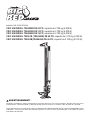
OWNER’S MANUAL
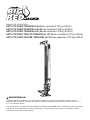
TRA8205B 20” UTILITY JACK; Capacity 6,000-lbs. (2,700-kgs)
TRA8335B 33” UTILITY JACK; Capacity 6,000-lbs. (2,700-kgs)
TRA8365B 36” UTILITY JACK; Capacity 6,000-lbs. (2,700-kgs)
TR6501B (TRA8485B) 48” UTILITY JACK; Capacity 6,000-lbs. (2,700-kgs)
TR6502B (TRA8605B) 60” UTILITY JACK; Capacity 6,000-lbs. (2,700-kgs)
Questions, problems, missing parts? Before returning to your retailer, call our customer service department at
1-888-44-TORIN (1-888-448-6746), 8 a.m.- 5 p.m., PST, Monday-Friday.
Read carefully and understand all ASSEMBLY AND OPERATION INSTRUCTIONS before operating. Failure
to follow the safety rules and other basic safety precautions may result in serious personal injury.
Version 03032017

2
IMPORTANT
Before You Begin Register This Product.
For future reference, record the model name, model number, date of manufacture and purchase date of this
product. You can nd this information on the product.
Model Name ________________________
Model Number ________________________
Date of Manufacture _______________________
Date of Purchase ________________________
OWNER / USER RESPONSIBILITY
DO NOT OPERATE OR REPAIR THIS PRODUCT WITHOUT READING THIS MANUAL.
Read and follow the safety instructions. Keep Instructions readily available for operators. Make certain all
operators are properly trained and understand how to safely and correctly operate the product. By proceeding
you agree that you fully understand and comprehend the full contents of this manual. Failure to operate this
product as intended may cause injury or death. The manufacturer is not responsible for any damages or injury
caused by improper use or neglect. Allow product operation only with all parts in place and operating safely.
Use only genuine replacement parts. Service and maintain the product only with authorized or approved
replacement parts; negligence will make the product unsafe for use and will void the warranty. Carefully
inspect the product on a regular basis and perform all maintenance as required. Store these instructions
in a protected dry location. Keep all decals on the product clean and visible. Do not modify and/or use for
any application other than that for which this product was designed. If you have any questions relative to a
particular application, DO NOT use the product until you have rst contacted the distributor or manufacturer to
determine if it can or should be performed on the product.
For technical questions please call 1-888-448-6746.
INTENDED USE
This universal Ratcheting Utility Jack is very versatile. It's a perfect choice for any application that deals with
lifting, pulling, clamping or spreading. This product is tested for reliability and safety to meet ASME B30.1
Standards

3
GENERAL SAFETY RULES
SAVE THESE INSTRUCTIONS
IMPORTANT SAFETY CONSIDERATIONS
WARNING: Read and understand all instructions. Failure to follow all instructions listed below may result
in serious injury.
WARNING: The warnings, cautions, and instructions discussed in this instruction manual cannot
cover all possible conditions or situations that could occur. It must be understood by the operator
that common sense and caution are factors that cannot be built into this product, but must be supplied by
the operator.
CAUTION: Do not allow persons to operate or assemble this jack until they have read this manual and
have developed a thorough understanding of how the jack works.
JACK USE AND CARE
INSPECTION
• Do not modify the jack in any way. Unauthorized modication may impair the function and/or safety and
could affect the life of the equipment. There are specic applications for which the jack was designed.
• Always check of damaged or worn out parts before using the jack. Broken parts will affect the jack
operation. Replace or repair damaged or worn parts immediately.
• Store idle jack. When jack is not in use, store it in a secure place out of the reach of children. Inspect it for
good working condition prior to storage and before re-use.
• Not for use by children or people with reduced mental capacity.
• Do not use under the inuence of drugs or alcohol.
• Ensure children and other bystanders are kept at a safe distance when using product.
• Inspect the jack carefully before each use. Ensure the jack is not damaged, excessively worn, or missing
parts.
• Do not use the jack unless it is properly lubricated.
• Using a jack that is not in good clean working condition or properly lubricated may cause serious injury.
• Inspect the work area before each use. Make sure it is free and clear of any potential hazards.
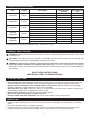
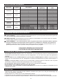
TECHNICAL SPECIFICATIONS
Safe Operating Temperature is between 40°F – 105°F (4°C - 41°C)
Item Length Description Specications
(Global)
Specications
(US)
TRA8205B 20-inch
Maximum Capacity 2,700 kgs 6,000-lbs
Minimum Lifting Height 130 mm 5.12 inch
Maximum Lifting Height 318 mm 12.52 inch
TRA8335B 33-inch
Maximum Capacity 2,700 kgs 6,000-lbs
Minimum Lifting Height 130 mm 5.12 inch
Maximum Lifting Height 670 mm 26.38 inch
TRA8365B 36-inch
Maximum Capacity 2,700 kgs 6,000-lbs
Minimum Lifting Height 130 mm 5.12 inch
Maximum Lifting Height 720 mm 28.35 inch
TR6501B
TRA8485B 48-inch
Maximum Capacity 2,700 kgs 6,000-lbs
Minimum Lifting Height 130 mm 5.12 inch
Maximum Lifting Height 1016 mm 40 inch
TR6502B
TRA8605B 60-inch
Maximum Capacity 2,700 kgs 6,000-lbs
Minimum Lifting Height 130 mm 5.12 inch
Maximum Lifting Height 1315 mm 51.77 inch

4
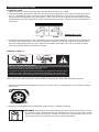
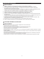
SAFETY MARKINGS
1. Study, understand, and follow all instructions before operating this device.
2. Ensure the jack is lubricated and in good working order before each use.
3. Do not exceed rated capacity. This is a lifting and pulling device only. Do not use to support load.
4. Ensure the work area is at and sufcient to hold the load. Shifting of the load or work area can cause the
jack to loose stability and shift or fall suddenly.
5. Use chocks or a blocking device on load before using jack.
6. Lift only on areas of a vehicle as specied by the vehicle manufacturer.
7. Only use adaptors and chains supplied by the manufacturer.
8. Ensure all chains or adaptors used have a rated load greater than that of the jack.
9. Keep head and hands clear of the range of movement of the jack handle. Unexpected shifting of the load
or loss of grip on the handle could cause it to snap back.
10. Always keep handle against the standard bar when changing the reversing latch. This could cause sudden
movement of the handle.
11. Do not use this jack for any use other than the manufacturer specied usage.
12. Failure to heed these markings may result in personal injury and/or property damage.
• Always inspect the jack before using, replace if damaged or malfunctioning.
• Do not remove any of the labels from the jack.
• Always ensure the jack is used on a hard at and level surface
• Never lift any load over the rated capacity.
• Always center jack under load.
• Never allow load to tilt on the jack as the jack may kick out causing injury to the operator and/ orcause the
load to fall.
• When using more than one jack to lift a load, each jack must have the same lifting capacity of the entire
load being lifted.
• Never force the Lifting Runners past the safety stop, as the Runner may come out of the jack and could
result in personal injury and properly damage.
• Always keep the Steel Standard Column lubricated for ease of operation and to prevent against rust.
WARNING!
WARNING!
GENERAL SAFETY INSTRUCTIONS

5
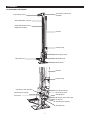
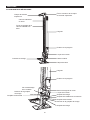
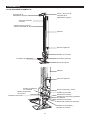
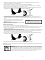
NO ASSEMBLY REQUIRED
Top Clamp Clevis Top Clamp Clevis Nut
and Bolt
Handle
Handle
Handle Clip
Reversing Latch
Small Runner
Base Plate
Handle Clip
Hex Bolt and Nut
Cap Screw with Washer
Climbing Pin Spring
Cross Pin
Reversing Latch
Climbing Pin
Shear Pin and Cotter Pin
Cross Pin
Climbing Pin Spring
Climbing Pin
Steel Standard Column
Lifting Runner
Steel Standard Column
Adjustment Holes
ASSEMBLY

6
OPERATION
CHOCK AND BLOCK (STABILIZE)
• Do not use this jack on curved or tubular vehicle bumpers. The vehicle could slip off the jack and fall,
causing serious injury or death. Do not raise inated tire more than 2" above the ground. Never attempt to
lift more than one wheel at a time.
• The working load of each chain or tow strap must be greater than the strength of the jack. If a chain or tow
strap breaks while winching, the load could shift or the chain or tow strap could snap back. When used as a
winch, the top clamp will support up to 3307 lbs. (1500 kg). If you go over this limit, the top clamp could
bend or break, causing the load to shift or the chain or tow strap to snap back. If that occurs, it could result
in damage or injury.
• The maximum clamping force is 750 lbs. (340 kg). If you exceed this limit, the top clamp could bend or
break, resulting in injury or damage.
• THIS JACK WILL NOT STABILIZE THE LOAD. You must chock and block (stabilize) the load to prevent it
from moving or falling. If a raised load falls, it can cause serious injury or death. Lowering the load can be
dangerous. Keep your head clear of the path of the handle. During lowering, the weight of the load pushes
up against the jack's handle. If your hands slip off the handle, or if the handle is horizontal when you move
the reversing latch, it may move up very quickly. If your head is in the handle's travel path, it could strike
you, causing serious injury or death.
• Do not use the jack to support a load. Securely chock and block (stabilize) the load to be lifted.
Never get under a raised load without properly chocking and supporting the load. If a raised load falls it can
cause serious injury or death.
• Never work under raised equipment unless additional supports are used under the lifted
equipment.
A chock is a wedge for steadying a body and holding it motionless, or for preventing the movement of a wheel.
When you block a load, you secure and support a load that is being lifted. The block(s) or stabilizer(s) should
have a weight capacity that is greater than the weight of the load which is being lifted.
WARNING! Additional - Mechanical Jack Operating Practices
The rated load of the mechanical jack shall not be exceeded.
WARNING!
DANGER: Do not use the jack to support a load. Securely chock and block (stabilize) the load to be lifted.
Never get under a raised load without properly chocking and supporting the load. If a raised load falls it
can cause serious injury or death. Always place the handle against the steel standard (bar) before moving
the reversing latch. This will prevent the handle from moving up and down rapidly, which could cause
serious injury or death if it comes into contact with any part of your body. Always keep your head out of the
travel path of the handle.

7
JACKING PRACTICES
COMMUNICATION
SYNCHRONIZED LIFTS (DO NOT SYNCHRONIZE LIFT VEHICLES)
a. All mechanical jacks shall be used according to the manufacturer's recommendations.
b. A plan should be developed and communicated to affected personnel before the jacking operation begins.
The plan should include load-handling procedures and communication methods.
c. Off-center loading of the primary load point should be avoided.
d. When jacking, ensure that the load avoids contact with any obstructions.
e. When jacking, ensure that the primary or auxiliary load point is properly positioned under the load to avoid
tip or edge.
f. When jacking one side or end of a load, ensure the opposing side or end is-stabilized with sufcient
blocking.
g. The jack handle, primary and auxiliary load points, and the jack base should be free of slippery material or
uids.
h. When jacking, a load should be raised or lowered in a limited range. Avoid jacking the side or end of the
load on more than a 3% grade.
i. When lifting one side of an object with a high center of gravity, personnel should be on the side of the load
that is being lifted.
j. A load shall not be left unattended while supported by jack. Jack Stands should be used to support
unattended loads.
k. The load weight and center of gravity shall be determined prior to selecting and placing jacks and blocking.
l. Before jacking a load, consideration shall be given to uids or other shifting materials that can change the
location of the center of gravity.
m. The base of the jack should be supported by a hard level surface (such as farm jack jacking pads,
concrete, steel, or wood blocking) capable of supporting the load.
n. The force of the jack's load point should be placed or distributed to prevent damage to the load.
o. A jack handle of the size and length specied by the manufacturer shall be used. Never use a over length
jack handle, extender, or "cheater pipe" over the handle.
p. Ensure there is adequate range of motion for the jack handle to completely engage the operating linkage
of the jack.
a. Communication between personnel involved in the lift operation shall be maintained continuously during
all jack movement. If at any time communication is disrupted, the jack operator(s) shall stop all movements
until communication is restored.
b. Signals to the jack operator should be in accordance with the ASME B30.1. If special signals are required,
they shall be agreed upon by the load-handling personnel prior to jacking operations.
Signals shall be discernible or audible at all times. No action shall be taken unless signals are clearly
under-stood.
c. Jack operators shall obey any stop signal.
(a) When using jacks to lift the entire load in a synchronized lift, uneven raising and lowering can cause cross
loading, instability, and overloading.
(b) Some loads may require multiple lifting points and complex lifting procedures. A qualied person shall
analyze the operation and instruct all personnel involved in the proper selection and positioning of the
jacks and the movements to be made.
(c) When using multiple ratchet jacks simultaneously, ensure they are identical type (manufacturer, make,
model, and capacity), or lifting rate to ensure they are evenly loaded during jacking.
(d) Unsynchronized lowering can cause an overload to a jack and may result in kickback of the jack handle or
instability of the load.

8
Blocking
Horizontal jacking
Note:
(a) While jacking, blocking should follow the load up or down to serve as an arresting device if the load falls.
(b) Wedges or shims should be used as necessary to ensure the load is completely supported at its blocking
points.
(c) Blocking shall be of sufcient thickness, width, and length to prevent shifting, toppling, or excessive
settlement of the load.
(d) Blocking shall be of sufcient strength to prevent crushing, bending failure or shear failure, and to
adequately transmit the load's weight to the supporting surface.
a. Applications may arise where jacks are used in a position other than vertical. These applications, referred
to as horizontal jacking, require special attention.
b. Horizontal jacking shall comply with the requirements of, Operating Practices, as applicable
c. A plan shall be developed and communicated to affected personnel before horizontal jacking operations
begin. The plan shall consider but not be limited to the following:
1. Load weight
2. Effects of friction
3. Angle from horizontal plane
4. Load stability and control
5. Obstructions
6. Jack base support
a. When jacking horizontally, the base of the jack should be perpendicular to the direction of load movement.
b. If multiple jacks are used, maintain parallel lines of force to prevent side loading of the jacks.
(a) No alterations, or modications shall be made to this product.
(b) All replacement parts including pins, bolts, caps, and keepers shall meet or exceed the original equipment
manufacturer's specications.
a. Personnel shall not place any part of their body between the jack and the load during lifting and lowering of
the load.
b. Personnel shall not place any part of their body under a load supported by a jack.
c. Personnel should not place any part of their body under blocking that is positioned to support the load,
when the load is supported by a jack.
d. Personnel shall not straddle the handle of the jack.
e. Personnel should ensure there is sufcient swing area to avoid pinch points while using the jack handle.
f. Personnel should not be on a load supported by jacks.
g. The jack operator should have rm footing and handle control while operating the jack.
h. Unsynchronized operation of multiple ratchet jacks may produce increased or uncontrollable handle force.
i. Personnel should avoid placing their head in the swing arc of the handle. Ratchet jack handles may
produce sudden kickback while lifting or lowering the load.
j. Ensure the handle load has been transferred to the jack before releasing the handle.
7. Jack support
8. Load contact point
9. Handle clearance
10. Center of gravity of the load
11. Personnel safety
Cautions to Personnel

9
OPERATING INSTRUCTIONS
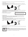
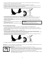
TO RAISE A LOAD
1. Place the jack on a hard and level surface beneath the load that is to be lifted.
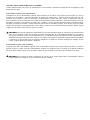
2. Following all safety precautions, place the foot of the jack beneath the load. Lift the reversing latch (20) to
the “UP” position and ensure it is locked in place. With the indentation in the latch rmly engaged in the
notch on the reversing switch (18) (see gure 1), jack up the nose until it comes into contact with the load
at the desired point of lift. Make sure a pause on this stage and check to ensure there are no obstacles for
a clean lift.
3. Pull down rmly and evenly on the handle and observe the load when rising. As the handle is pulled down,
you will hear the Climbing Pin (15) click into place as it locates in a hole in the steel bar (3). At this point,
relax the handle allowing the pin (15) to take the load. Raise the handle to the top of its stroke to take a
fresh purchase and pump the handle once again.
2. Keep the handle against the steel standard (column) when not lifting or lowering.
1. Securely chock and block (stabilize) the load you are going to lift. This will prevent it from rolling or shifting
as you lift it.
Never work under raised equipment unless additional supports are used under the lifted equipment.
THIS IS A LIFTING DEVICE ONLY!
• This jack is designed only for lifting part of the total vehicle.
• Do not move or dolly the vehicle while on the jack.
• The vehicle must be supported after lifting immediately by appropriately rated jack stands.
• NEVER go under a vehicle that is not supported with appropriately rated jacks stands.
• Use wheel chocks or other blocking device on opposing wheels before using jack stands.
DANGER: Always place the handle against the steel standard (bar) before moving
the reversing latch. This will prevent the handle from moving up and down rapidly,
which could cause serious injury or death if it comes into contact with any part of your
body. Always keep your head out of the travel path of the handle.
REVERSING LATCH
UP DOWN
RAISING A VEHICLE

10
3. Place the jack's base plate securely on a rm, level, and dry surface with the steel standard (column)
pointing vertical.
4. Lift the reversing latch until it locks in the “UP” position.
5. Grasp the handle or the handle socket and raise the lifting mechanism until the nose is completely and
securely under the load.
6. Grasp the handle rmly with both hands. Carefully pump the handle up and down to raise the load. Do not
use an extension on the handle.
• The load will be raised on each DOWN stroke of the handle.
• Watch the load and the jack carefully. Stop jacking if either one starts to move. Do not continue raising the
load unless it is safe to do so. When safe, stabilize and block the load.
7. When the load is raised to the desired height, place the handle in the upright position against the steel
standard (column).
8. Block the load securely with jack stands.
9. Lower the load onto the jack stands.
Important!
1. Do not use extensions on the handle.
2. Always keep a rm hold on the handle.
TO LOWER A LOAD
1. The jack must have a load on it (110 pounds or more) to lower step-by-step. Otherwise, the lifting
mechanism will slide down to the base plate, "dropping" your load.
2. Before you move the reversing latch down, keep the handle in the upright position against the steel
standard (column).
3. Move the reversing latch to the DOWN position.
• Taking all necessary precautions, with the load on the jack and ensuring the handle is in the full upright
position, trip the reversing latch (17) so that it’s in the “DOWN” position (i.e. the indentation on the latch)
becomes disengaged from the notch on the reversing switch.
4. Grasp the handle rmly with both hands. Carefully pump the handle up and down to begin lowering the
load.
5. The load will be lowered on each UP stroke of the handle.
Important! The jack must be loaded with a minimum of 110lbs to lower step by step, otherwise the lifting nose
(large runner) will drop.
DANGER: Lowering the load can be dangerous. Keep your head clear of the path
of the handle. During lowering, the weight of the load pushes UP against the Jack's
handle. If your hands slip off the handle, or if the handle is horizontal when you move
the reversing latch, it may move up very quickly. If your head is in the handle's travel
path, it could strike you, causing serious injury or death.

11
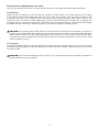
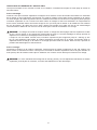
WINCHING OR CLAMPING WITH THE JACK
For Winching:
You may use this jack as a winch or clamp. See the pictures on this page and follow these instructions.
Make sure the top clamp is in line with the bar. Install one end of chain or tow strap securely to the object
to be winched, and securely attach the other end of the chain or tow strap to the top clamp of the jack. Use
a shackle if the chain or tow straps will not t through the Top Clamp of the jack. Take another chain or tow
strap and secure one end to a xed, stable object, and the other end around the lifting nose on the jack (do
not attach chain or shackle to bottom hole of the lifting nose). If the xed object is a tree, follow Tread Lightly
principles and use a tree strap. Operate the jack as you would for raising or lowering a load.
DANGER: The working load of each chain or tow strap must be greater than the strength of the jack. If
a chain or tow strap breaks while winching, the load could shift or the chain or tow strap could snap back.
When used as a winch, the top clamp will support up to 3307 lbs. If you go over this limit, the top clamp
could bend or break, causing the load to shift or the chain or tow strap to snap back. If that occurs, it could
result in damage or injury.
For Clamping:
Loosen the top clamp bolt. Turn the top clamp 90° to the steel bar, and retighten the bolt. You can connect the
top clamp anywhere along the steel standard (bar) to use the jack as a clamp. Operate the jack as you would
for raising a load.
DANGER: The maximum clamping force is 750 lbs. If you exceed this limit, the top clamp could bend or
break, resulting in injury or damage.

12
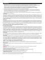
MAINTENANCE
• Maintain your jack. It is recommended that the general condition of any jack be examined before it is
used. Keep your jack in good repair by adopting a program of conscientious repair and maintenance. Have
necessary repairs made by qualied service personnel.
• Follow the maintenance instructions carefully to keep your equipment in good working condition.
Never perform any maintenance on the equipment while it is under a load.
a. All moving parts of the jack should be regularly cleaned.
b. Lubricate parts as required by the manufacturer’s specications. The type of lubricant should be as
specied by the manufacturer or a qualied person. Lubrication systems should be checked to verify proper
operation.
c. If additional maintenance is required, it should be completed in accordance with the instructions of the
manufacturer or qualied person.
Inspection
You should inspect the product for damage, wear, broken or missing parts (e.g.: pins) and that all components
function before each use. Follow lubrication and storage instructions for optimum product performance. Check
the climbing pins to make sure that they are not worn or damaged.
Check the steel standard (bar) to make sure that it is straight and that nothing is blocking the holes.
Do not use the jack unless it is in good, clean working condition and properly lubricated.
Binding
If the product binds while under a load, use equipment with equal or a larger load capacity to lower the load
safely to the ground. After un-binding; clean, lubricate and test that equipment is working properly. Rusty
components, dirt, or worn parts can be causes of binding Clean and lubricate the equipment as indicated in
the lubrication section. Test the equipment by lifting without a load. If the binding continues, contact Customer
Service.
If your jack binds
As your jack becomes older, the climbing pins may start binding in the holes of the steel standard (bar). This
will prevent the jack from operating properly and safely. Rusty climbing pins, dirt, or a worn bar can cause
binding. Clean and lubricate the lifting mechanism. Test the jack by jacking it up without a load. If the binding
continues, refer to the after sale parts and service. If your jack binds while under a load, use a jack with equal
or larger load capacity to lower the load safely to the ground. Repeat the steps in this paragraph to the binding
jack.
Cleaning
If the moving parts of the equipment are obstructed, use cleaning solvent or another good degreaser to clean
the equipment. Remove any existing rust, with a penetrating lubricant.
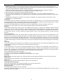
Lubrication
If the moving parts of the jack or the steel standard) bar) are clogged, use air pressure, water pressure, or
a stiff brush to clean. Use a non-ammable cleaning solvent or another good degreaser to clean the jack.
Remove any existing rust, preferably with a penetrating lubricant. Then lubricate the jack using white lithium
grease, light penetrating oil, or a silicon or Teon spray at the following points:
Use a good lubricant on all moving parts.
For light duty use, lubrication is needed once a month.
For heavy and constant use, lubrication is recommended every week.
Steel Bar:
Keep the front and back edges of the steel standard (column) lightly lubricated and free from dirt and rust.
Pitman Pin:
Keep the pitman pin lubricated or it will damage the handle socket and pitman.
Shear Pin:
Keep the shear bolt clean and lubricated to keep it from wearing out.
Climbing Pins and springs:
Keep both climbing pins and springs lubricated and free from dirt and rust.
Do not use motor oil or grease to lubricate the jack
Rust Prevention:
Check daily for any signs of rust or corrosion.
Without a load lift the equipment as high as it goes and look under and behind the lifting points. If signs of rust
are visible clean as needed.

13
WARNING: Jack is not self-lubricating. It will not operate safely without proper lubrication.
Storing the Jack
1. Place the handle in the upright position against the steel standard (column).
2. Raise the reversing latch until it locks in the UP position.
3. Store the jack in a upright position in a dry location, preferably indoors. If the jack is stored outdoors, or is
stored in a Loc-Rac or 4x4 RAC use a jack protector.
4. Store in a dry location, recommended indoors.
5. Mechanical jacks should be stored in an area where they will not be subjected to damage.
6. If extreme temperatures or chemically active or abrasive environments are involved, the guidance provided
in shall be followed.
7. Temperature - When mechanical jacks are to be used at temperatures above 140"F (60"C) or below -20"F
(-29"C), the jack manufacturer or a qualied person should be consulted.
8. Chemically Active Environments -The strength and operation of mechanical jacks can be affected by
chemically active environments such as caustic or acid substances or fumes. The jack manufacturer or a
qualied person should be consulted before mechanical jacks are used in chemically active environments.
9. Other Environments - The internal workings of jacks can be affected by high moisture, gravel or sand, silt,
grit, or other dust-laden air. Jacks subject to these environments should have their inner components
frequently cleaned, inspected, and lubricated.
Note: If the jack is stored outdoors, be sure to lubricate all parts before and after use to ensure the
jack stays in good working condition.

14
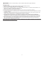
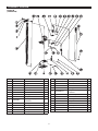
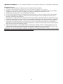
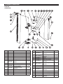
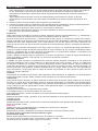
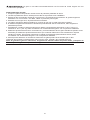
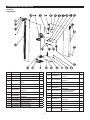
ASSEMBLY DIAGRAM
REF# PART# DESCRIPTION QTY
1 GB6170-M12 Nut M12 1
2 GB93-12 Spring washer M12 1
3 GB97.1-12 Washer M12 1
4 Top clamp clevis 1
5 TRA8205B-1 Steel standard column 1
6 TRA8205B-2 Small runner 1
7 TRA8205B-3 Locking pin with wire retainer 1
8 Base plate 1
9 TRA8205B-4 Climping pin spring
Ø16x30mm 2
10 TRA8205B-5 Cross pin Ø5x52mm 2
11 TRA8205B-6 Climbing pin 2
12 Pitman arm 1
13 TRA8205B-7 Pitman pin 2
14 TRA8205B-8 Cotter pin 2
REF# PART# DESCRIPTION QTY
15 TRA8205B-9 Reversing switch column 1
16 GB6170-M8x40 Hex head screw M8x40mm 1
17 TRA8205B.1-1 Handle 1
18 TRA8205B.1-2 Handle grip 1
19 TRA8205B-10 Spring for reversing lever
Ø13x60mm 1
20 GB6170-M8x16 Hex head cap screw M8x16mm 1
21 GB97.1-8 Washer M8 1
22 TRA8205B-11 Reversing latch 1
23 TRA8205B-12 Shear pin Ø12x22mm 1
24 Handle socker 1
25 TRA8205B-13 Handle clip 1
26 Lifting runner 1
27 GB6170-M12x50 Hex head screw M12x50mm 1
TRA8205B

15
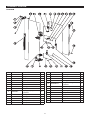
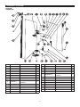
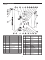
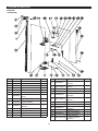
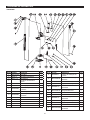
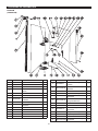
ASSEMBLY DIAGRAM
REF# PART# DESCRIPTION QTY
1 GB6170-M12 Nut M12 1
2 GB93-12 Spring washer M12 1
3 GB97.1-12 Washer M12 1
4 Top clamp clevis 1
5 TRA8335B-1 Steel standard column 1
6 TRA8335B-2 Small runner 1
7 TRA8335B-3 Locking pin with wire retainer 1
8 Base plate 1
9 TRA8335B-4 Climping pin spring
Ø16x30mm 2
10 TRA8335B-5 Cross pin Ø5x52mm 2
11 TRA8335B-6 Climbing pin 2
12 Pitman arm 1
13 TRA8335B-7 Pitman pin 2
14 TRA8335B-8 Cotter pin 2
REF# PART# DESCRIPTION QTY
15 TRA8335B-9 Reversing switch column 1
16 GB6170-M8x40 Hex head screw M8x40mm 1
17 TRA8335B.1-1 Handle 1
18 TRA8335B.1-2 Handle grip 1
19 TRA8335B-10 Spring for reversing lever
Ø13x60mm 1
20 GB6170-M8x16 Hex head cap screw M8x16mm 1
21 GB97.1-8 Washer M8 1
22 TRA8335B-11 Reversing latch 1
23 TRA8335B-12 Shear pin Ø12x22mm 1
24 Handle socker 1
25 TRA8335B-13 Handle clip 1
26 Lifting runner 1
27 GB6170-M12x50 Hex head screw M12x50mm 1
TRA8335B

16
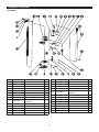
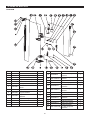
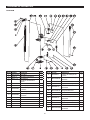
ASSEMBLY DIAGRAM
REF# PART# DESCRIPTION QTY
1 GB6170-M12 Nut M12 1
2 GB93-12 Spring washer M12 1
3 GB97.1-12 Washer M12 1
4 Top clamp clevis 1
5 TRA8365B-1 Steel standard column 1
6 TRA8365B-2 Small runner 1
7 TRA8365B-3 Locking pin with wire retainer 1
8 Base plate 1
9 TRA8365B-4 Climping pin spring
Ø16x30mm 2
10 TRA8365B-5 Cross pin Ø5x52mm 2
11 TRA8365B-6 Climbing pin 2
12 Pitman arm 1
13 TRA8365B-7 Pitman pin 2
14 TRA8365B-8 Cotter pin 2
REF# PART# DESCRIPTION QTY
15 TRA8365B-9 Reversing switch column 1
16 GB6170-M8x40 Hex head screw M8x40mm 1
17 TRA8365B.1-1 Handle 1
18 TRA8365B.1-2 Handle grip 1
19 TRA8365B-10 Spring for reversing lever
Ø13x60mm 1
20 GB6170-M8x16 Hex head cap screw M8x16mm 1
21 GB97.1-8 Washer M8 1
22 TRA8365B-11 Reversing latch 1
23 TRA8365B-12 Shear pin Ø12x22mm 1
24 Handle socker 1
25 TRA8365B-13 Handle clip 1
26 Lifting runner 1
27 GB6170-M12x50 Hex head screw M12x50mm 1
TRA8365B

17
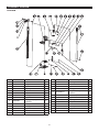
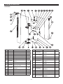
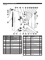
ASSEMBLY DIAGRAM
REF# PART# DESCRIPTION QTY
1 GB6170-M12 Nut M12 1
2 GB93-12 Spring washer M12 1
3 GB97.1-12 Washer M12 1
4 Top clamp clevis 1
5 TRA8485B-1 Steel standard column 1
6 TRA8485B-2 Small runner 1
7 TRA8485B-3 Locking pin with wire retainer 1
8 Base plate 1
9 TRA8485B-4 Climping pin spring
Ø16x30mm 2
10 TRA8485B-5 Cross pin Ø5x52mm 2
11 TRA8485B-6 Climbing pin 2
12 Pitman arm 1
13 TRA8485B-7 Pitman pin 2
14 TRA8485B-8 Cotter pin 2
REF# PART# DESCRIPTION QTY
15 TRA8485B-9 Reversing switch column 1
16 GB6170-M8x40 Hex head screw M8x40mm 1
17 TRA8485B.1-1 Handle 1
18 TRA8485B.1-2 Handle grip 1
19 TRA8485B-10 Spring for reversing lever
Ø13x60mm 1
20 GB6170-M8x16 Hex head cap screw M8x16mm 1
21 GB97.1-8 Washer M8 1
22 TRA8485B-11 Reversing latch 1
23 TRA8485B-12 Shear pin Ø12x22mm 1
24 Handle socker 1
25 TRA8485B-13 Handle clip 1
26 Lifting runner 1
27 GB6170-M12x50 Hex head screw M12x50mm 1
TR6501B
(TRA8485B)

18
ASSEMBLY DIAGRAM
REF# PART# DESCRIPTION QTY
1 GB6170-M12 Nut M12 1
2 GB93-12 Spring washer M12 1
3 GB97.1-12 Washer M12 1
4 Top clamp clevis 1
5 TRA8605B-1 Steel standard column 1
6 TRA8605B-2 Small runner 1
7 TRA8605B-3 Locking pin with wire retainer 1
8 Base plate 1
9 TRA8605B-4 Climping pin spring
Ø16x30mm 2
10 TRA8605B-5 Cross pin Ø5x52mm 2
11 TRA8605B-6 Climbing pin 2
12 Pitman arm 1
13 TRA8605B-7 Pitman pin 2
14 TRA8605B-8 Cotter pin 2
REF# PART# DESCRIPTION QTY
15 TRA8605B-9 Reversing switch column 1
16 GB6170-M8x40 Hex head screw M8x40mm 1
17 TRA8605B.1-1 Handle 1
18 TRA8605B.1-2 Handle grip 1
19 TRA8605B-10 Spring for reversing lever
Ø13x60mm 1
20 GB6170-M8x16 Hex head cap screw M8x16mm 1
21 GB97.1-8 Washer M8 1
22 TRA8605B-11 Reversing latch 1
23 TRA8605B-12 Shear pin Ø12x22mm 1
24 Handle socker 1
25 TRA8605B-13 Handle clip 1
26 Lifting runner 1
27 GB6170-M12x50 Hex head screw M12x50mm 1
TR6502B
(TRA8605B)

19
WARRANTY NOTICE
WARRANTY INFORMATION
This equipment is covered under a 1-year limited warranty when used as recommended. Only those
items listed with a Part # are available for purchase. For assistance with the operation or the availability of
replacement parts, contact our Parts and Warranty Department at 1-888-44-TORIN (1-888-448-6746). Please
have available a copy of your receipt, the model number of the product, serial number, and specic details
regarding your question.
Not all equipment components are available for replacement; illustrations provided are a convenient reference
of location and position in the assembly sequence.
The manufacturer reserves the rights to make design changes and or improvements to product lines
and manuals without notice.
We want to know If you have any concerns with our products. If so, please call toll-free for Immediate
assistance. For additional web customer support help inquiries visit the Customer Service section at: http://
www.torin-usa.com.

20
TORIN ONE YEAR LIMITED WARRANTY
Torin Inc.® has been producing quality automotive repair and maintenance products since 1968. All products
sold are felt to be of the highest quality and are covered by the following warranty:
With proof of purchase for a period of one year from the date of that purchase, the manufacturer will repair or
replace, at its discretion, without charge, any of its products or parts thereof which fail due to a defect in
material or workmanship. This warranty does not cover damage or defects caused by improper use, careless
use or abuse of the equipment. This warranty does not cover parts normally considered to wear out or be
consumed in the normal operation of the equipment. Except where such limitations and exclusions are
specically prohibited by applicable law, (1) the CONSUMERS SOLE AND EXCLUSIVE REMEDY SHALL BE
THE REPAIR OR REPLACEMENT OF DEFECTIVE PRODUCTS AS DESCRIBED
ABOVE, and (2) THE MANUFACTURER SHALL NOT BE LIABLE FOR ANY CONSEQUENTIAL OR
INCIDENTAL DAMAGE OR LOSS WHATSOEVER, and (3) THE DURATION OF ANY AND ALL
EXPRESSED AND IMPLIED WARRANTIES, INCLUDING, WITHOUT LIMITATION, ANY WARRANTIES OF
MERCHANTABILITY AND FITNESS FOR A PARTICULAR PURPOSE, IS LIMITED TO A PERIOD OF ONE
YEAR FROM DATE OF PURCHASE. Product alteration in any manner by anyone other than us, with the sole
exception of alterations made pursuant to product instructions and in a workman like manner. You
acknowledge and agree that any use of the product for any purpose other than the specied use(s) stated in
the product instructions is at Your own risk.
Always check for damaged or worn out parts before using any product. Broken parts will affect the equipment
operation. Replace or repair damaged or worn parts immediately. Do not modify the product in any way.
Unauthorized modication may impair the function and/or safety and could affect the life of the equipment.
There are specic applications for which products are designed and tested during production. Manufacturer
provided warranted items are not authorized to be repaired by anyone other than the manufacturer or
manufacture approved repair person. Distributor does not have authorization to amend these statements. You
acknowledge and agree that any modication of the product for any purpose other than manufacturer
completed repairs is at your own risk. Before using this product, read the owner's manual completely and
familiarize yourself thoroughly with the product and the hazards associated with its improper use.
IMPORTANT: BEFORE FIRST USE on any Lift verify that a daily inspection has been completed and that all
components are in the proper working order.
This limited warranty gives you specic legal rights, and you also may have other rights, which vary from
state to state. Some states do not allow limitations or exclusions on implied warranties or incidental or
consequential damages, so the above limitations may not apply to You. This limited warranty is governed by
the laws of the State of California, without regard to rules pertaining to conicts of law. The state courts
located in San Bernardino County, California shall have exclusive jurisdiction for any disputes relating to this
warranty.
Manufacturer reserves the rights to make design changes and or improvements to this product lines and
manual without notice. We at Torin have taken every effort to ensure complete and accurate instructions have
been included in this manual. However, possible product updates, revisions and or changes may have
occurred since this printing. Torin Inc. reserves the right to change specications without incurring any
obligation for equipment previously or subsequently sold. Not responsible for typographical errors.
Alternately Customer Service can be reached through www.torin-usa.com or via email at
Not all equipment components are available for replacement, but are illustrated as a convenient reference of
location and position in the assembly sequence. Contact Customer Service for equivalent component. When
you contact us, please have your Product’s Model number, Serial Number and Description ready so that we
may help you efciently. This information can be found on a sticker on the product.
For any warranty support or if your Torin® equipment is not functioning properly contact
Torin® Customer Service directly by telephone at 1-888-44-TORIN (1-888-448-6746)
8:00am – 5:00pm Pacic Time, Monday – Friday
www.torin-usa.com Made in China
La page est en cours de chargement...
La page est en cours de chargement...
La page est en cours de chargement...
La page est en cours de chargement...
La page est en cours de chargement...
La page est en cours de chargement...
La page est en cours de chargement...
La page est en cours de chargement...
La page est en cours de chargement...
La page est en cours de chargement...
La page est en cours de chargement...
La page est en cours de chargement...
La page est en cours de chargement...
La page est en cours de chargement...
La page est en cours de chargement...
La page est en cours de chargement...
La page est en cours de chargement...
La page est en cours de chargement...
La page est en cours de chargement...
La page est en cours de chargement...
La page est en cours de chargement...
La page est en cours de chargement...
La page est en cours de chargement...
La page est en cours de chargement...
La page est en cours de chargement...
La page est en cours de chargement...
La page est en cours de chargement...
La page est en cours de chargement...
La page est en cours de chargement...
La page est en cours de chargement...
La page est en cours de chargement...
La page est en cours de chargement...
La page est en cours de chargement...
La page est en cours de chargement...
La page est en cours de chargement...
La page est en cours de chargement...
La page est en cours de chargement...
La page est en cours de chargement...
La page est en cours de chargement...
La page est en cours de chargement...
La page est en cours de chargement...
-
 1
1
-
 2
2
-
 3
3
-
 4
4
-
 5
5
-
 6
6
-
 7
7
-
 8
8
-
 9
9
-
 10
10
-
 11
11
-
 12
12
-
 13
13
-
 14
14
-
 15
15
-
 16
16
-
 17
17
-
 18
18
-
 19
19
-
 20
20
-
 21
21
-
 22
22
-
 23
23
-
 24
24
-
 25
25
-
 26
26
-
 27
27
-
 28
28
-
 29
29
-
 30
30
-
 31
31
-
 32
32
-
 33
33
-
 34
34
-
 35
35
-
 36
36
-
 37
37
-
 38
38
-
 39
39
-
 40
40
-
 41
41
-
 42
42
-
 43
43
-
 44
44
-
 45
45
-
 46
46
-
 47
47
-
 48
48
-
 49
49
-
 50
50
-
 51
51
-
 52
52
-
 53
53
-
 54
54
-
 55
55
-
 56
56
-
 57
57
-
 58
58
-
 59
59
-
 60
60
-
 61
61


BigRed TRA7224B Mode d'emploi
- Taper
- Mode d'emploi
- Ce manuel convient également à
dans d''autres langues
Documents connexes

Autres documents
-
 Big Red - Torin 9063439 Le manuel du propriétaire
-
Power Fist 8760662 Le manuel du propriétaire
-
Powerfist 8760647 Le manuel du propriétaire
-
Wacker Neuson LTN6K-V S Manuel utilisateur
-
Mazda MX-5 Miata 2000 Le manuel du propriétaire
-
Daewoo MUSSO SPORTS 2005 Le manuel du propriétaire
-
Wacker Neuson LTE4K Manuel utilisateur
