
1
SF 10C SUB Subwoofer • Setup Guide
This guide provides instructions for an experienced installer to install the Extron SF 10C SUB
subwoofer and to make all connections. The subwoofer typically is installed above a suspended
ceiling, but can also be placed on a horizontal surface with an optional oor kit.
Installation consists of the following operations:
•
Mounting the Subwoofer
•
Mounting the Port Tube
•
Installing the Grille
•
Connection and Operation
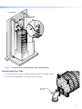
Mounting the Subwoofer
The SF 10C SUB can be suspended in a ceiling or rested on the oor.
Ceiling Mounting
The subwoofer can be suspended using the included aircraft cables (see “Aircraft cable installation”) or, optionally, with threaded rods
acquired locally (see Threaded rod installation on page 3).
WARNING:
AVERTISSEMENT :
• Properly suspending equipment requires training and expertise. Improper rigging of suspended equipment can cause the speaker
to fall, resulting in death, personal injury, equipment damage, and legal liability. Installation must be carried out by fully qualied
installers, in accordance with all required safety codes and standards at the place of installation.
• Il est indispensable de disposer de compétences techniques pour pouvoir suspendre l’équipement. Une manipulation incorrecte
de l’équipement suspendu peut provoquer la chute de l’enceinte, entraînant la mort, des lésions corporelles, des dégâts
matériels, et engageant la responsabilité d’un individu. L’installation doit être effectuée par des installateurs hautement qualiés,
conformément à l’ensemble des codes et des normes de sécurité réglementaires sur le lieu de l’installation.
•
The legal r
equirements for suspending equipment vary from country to country. Extron strongly recommends that you consult
your local safety standards ofce before installing any product. Extron also recommends that you thoroughly check any laws and
bylaws prior to installation.
•
Les conditions juridiques r
elatives à la suspension d’équipements varient de pays en pays. Extron vous recommande vivement de
consulter les standards de sécurité en vigueur dans votre pays avant d’installer un produit. Extron vous recommande également
de vérier minutieusement toute loi et tout règlement avant l’installation.
ATTENTION:
• Installation and service must be performed by authorized personnel only.
• L’installation et l’entretien doivent être effectués par le personnel autorisé uniquement.
• This unit must be repaired by personnel trained by Extron or returned to Extron for repair.
• Cette unité doit être réparée par un technicien formé par Extron ou renvoyée à Extron pour réparation.
Aircraft cable installation
Suspend the subwoofer above a false ceiling using the included aircraft cables using the following suboperations:
• Remove ceiling tile and install suspension cables
• Suspend the main subwoofer enclosure from the ceiling
IMPORTANT:
Go to www.extron.com for the complete
user guide, installation instructions, and
specifications before connecting the
product to the power source.
DANGER: This is the Danger style to use without bullets. The word “DANGER” must be 10 points regardless of other font
size used.
• A statement in 75 bold that “<whatever> may result in Serious injury or death” must start a Danger statement.
DANGER:
Danger cont. The word “DANGER” must be 10 points regardless of other font size used.
• For a bullet that is for “sub bullets,” how does this look.
DANGER:
• <whatever> may result in Serious injury or death. This is the
Danger bullet1 style. The word “DANGER” must be
10 points regardless of other font size used.
This is the
Danger bullet1 cont style. The word “DANGER” must be 10 points regardless of other font size used.
• This is the
Danger bullet 2 style. Use when space is an issue and having the wrap different helps save space.
The left indent is set at 0.25 inches. The word “DANGER” must be 10 points regardless of other font size used.
This is the
Danger bullet 2 cont style.. The word “DANGER” must be 10 points regardless of other font size
used.
WARNING: This is a warning style. The word “WARNING” must be 10 points regardless of other font size used.
CAUTION:
This is a caution sytle. The word “CAUTION” must be 10 points regardless of other font size used.
ATTENTION: This is an Attention style. The word “ATTENTION” may be the same font size as the rest of the
attention statement.
• This This is an Attention style. The word “ATTENTION” may be the same font size as the rest of the attention statement.
NOTE: Note style
TIP: Tip Text
Tip Text, cont’d
• TIPS: • Tips Bullet
• Tips_Bullet Ind_1
• Tips_Bullet Ind_L2
NOTES:
• If the new document is Revision A, delete xxxx- and this NOTE.
• If the new document is Revision B or higher, replace xxxx- with the year
the Revision A was released and delete this note.
• Delete this NOTE text frame.
NOTES:
• Safety Guide statement should go somewhere close to where I have it.
• If you need to move everything down, that’s okay.
• If you have more space on the first page, you can put it there.
• First page is the last resort move.

2
SF 10C SUB Subwoofer • Setup Guide (Continued)
Remove ceiling tile and install suspension cables
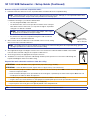
1. Determine where the subwoofer is to be suspended and its orientation above the suspended ceiling.
NOTE: Remember that the soun d from the unit is directed out the port. Therefore, although you can suspend the subwoofer in
any horizontal orientation, the port needs to be pointed into the listening space.
Consider the following as you make this determination:
Do not install the
C-ring beyond the
edge of ceiling tile.
• The size (length and width) of the subwoofer.
• The desired location of the woofer port. Ensure that the center of the port
tube will be at least 5-3/16 inches (13.7 cm) from the edge of suspended
ceiling tile once that tile is installed.
NOTE: This positioning ensures that the grille adapter and C-ring t
properly once installed (see the gure at right).
• Any obstructions above the suspended ceiling that could constrain the
orientation of the suspended subwoofer.
2.
At the location wher
e the subwoofer is to be installed, remove as many ceiling
tiles as necessary to install the subwoofer.
NOTE: The number of tiles to remove depends on the height of the structural ceiling above the suspended ceiling, given the
10-degree spread from the subwoofer to the structural ceiling.
3.
At an appr
oximate angle of 10 degrees out from each corner of where the subwoofer will be installed, mark and drill
four holes in the structural ceiling for the suspension cable anchors.
4. Screw a lag eye bolt (or an appropriate anchor) into each hole.
5. Thread the loose end of the suspension cable through the bolt eyehole, pass the loose end of the cable through the
looped end and tighten. Allow each cable to hang.
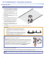
Suspend the main subwoofer enclosure from the ceiling
ATTENTION: The SF 10C SUB is heavy, approximately 38 pounds (17 kg), and bulky.
ATTENTION : La SF 10C SUB est lourde, et pèse environ 17 kg (38 livres), et est volumineuse.
• Use at least two people to install the subwoofer; one person to lift the unit into position AND to hold it, the second person to
fasten the suspension cables.
•
Il faut au minimum deux personnes pour installer le caisson de grave ; la pr
emière pour mettre l’unité en place ET la tenir, et la
seconde pour raccorder les câbles de suspension.
• Consider using a scissor-lift or other lifting apparatus rather than a ladder to work in the ceiling.
• Songez à utiliser une nacelle élévatrice ou tout équipement similaire plutôt qu’une échelle pour travailler au plafond.
• Do not rest the subwoofer on the ceiling grid, even temporarily.
• Ne posez pas le caisson de grave sur la grille de plafond, même temporairement.
TIP: If a scissor-lift is not available, the speaker can be hoisted using the suspension cables.

3
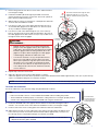
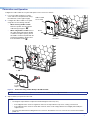
1. Remove the grommets from all four corners of the subwoofer frame
Thread the cable down through the cable
gripper, through the eye of one of the
eyebolts, and back up through the lock.
Cable
Gripper
Plunger
Eyebolt
≥2"
(50 mm)
≥1"
(25 mm)
≥2"
(50 mm)
Countersunk
Washer
Locking Nut
(not shown)
(see the gure at right).
2.
Install the included eyebolts thr
ough the provided countersunk
washers and into the four holes on the frame. Secure the eyebolts in
place with the provided locking nuts.
3. With the help of at least one other person, carefully lift the subwoofer
enclosure into the installation location.
4.
Pass the loose end of one of the cables down thr
ough one hole of
an included cable gripper. Ensure that about 12 to 15 inches (30 to
38 cm) of cable has exited the gripper.
5. Pass the loose end of the cable through the eye of one of the eye
bolts on the subwoofer enclosure and then through the other hole in
the cable gripper. Ensure that at least 1 inch (2.5 cm) of cable comes
through the other end of the gripper.
WARNING:
AVERTISSEMENT :
• Maintain at least a 2 inch (5 cm) clearance between the
plunger on the cable gripper and any other object in the
ceiling space. This includes the space between the eyebolt
below the gripper and the mounting hardware above the
gripper. If an object strikes the plunger, the cable gripper
could disengage and allow the subwoofer to fall.
• Conservez au minimum 5 cm (2”) d’espace libre entre le
piston sur le serre-câble et tout autre objet se trouvant
dans l’espace plafond. Il s’agit de l’espace entre l’anneau
de levage sous le serre-câble et le matériel de montage
au-dessus du serre-câble. Si un objet heurte le piston, le
serre-câble pourrait se desserrer et entraîner la chute du
caisson de basses.
6. Repeat steps 3 and 4 for each corner.
7.
Adjust the cable tension thr
ough all cable grippers so that the
subwoofer appears level to the critical eye and to ensure that its bottom brackets will be approximately 1 inch (2.5 cm) from the top
surface of suspended ceiling tile once that tile is installed.
NOTE: The exact height of the subwoofer is not critical at this point. You will make nal adjustments after the grille is installed.
Threaded rod installation
Secure the subwoofer to the structural ceiling using threaded rods as follows:
NOTES:
• Extron recommends 1/4-inch or 3/8-inch diameter threaded rods for installing this product.
•
The thr
eaded rod should be properly secured to the ceiling structure. For example, properly fasten a
unistrut to the ceiling structure and attach threaded rods using nuts and washers.
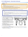
8. Fasten four threaded rods to the support structure. Extron recommends fastening the rods to
unistruts, one over each corner of the subwoofer installation location (see the gure at right).
9. Fasten a rod to each corner securing point of the subwoofer with nuts and washers.
10. Adjust all the nuts that secure the subwoofer to the ceiling so that the subwoofer appears level
to the critical eye and to ensure that its bottom brackets will be approximately 1 inch (2.5 cm)
from the top surface of suspended ceiling tile once that tile is installed.
NOTE: The exact height of the subwoofer is not critical at this point. You will make nal
adjustments after the grille is installed.
Insert threaded
rods through holes
on the ends of the
mounting bracket.
Attach washer and nut and secure.
Grommet
1. 1. Removing the grommets before installation of the eyebolts
2. 2. Feeding the eyebolt through the countersunk washer before feeding it through the bracket.
3. 3. Securing the eyebolt with one lock nut.
4. • Figure changes
5. o Update all gures showing the eyebolt to reect the changes
6. o Update all gures showing the port tube to reect the new external ange. (Since we are already touching the guides)

4
SF 10C SUB Subwoofer • Setup Guide (Continued)
Resting on a Floor
ATTENTION:
• The SF 10C SUB must have rebreaks installed in the wall, above and below it, when it is protruding through a wall, to meet UL
requirements.
•
Le
SF 10C SUB doit disposer de systèmes coupe-feu installés au mur, au-dessus et au-dessous de l’unité, lorsqu’elle est placée
en saillie du mur, an de satisfaire les exigences de l’UL.
• The subwoofer must be securely fastened to the stud or other stationary surface.
•
Le caisson de grave doit êtr
e solidement xé au montant ou à une autre surface stationnaire.
The subwoofer can be rested on a oor using the optional oor mounting kit, as follows:
1.
Determine wher
e the subwoofer is to be placed and its orientation (port tube on top or port tube on the bottom).
NOTE:
• Remember that the sound from the unit is directed out the port. Therefore, the port needs to be pointed into the listening
space.
•
To ensur
e that the Extron grille ts fully into any masking wall or other partition, the center of the port tube must be at least
5-3/16 inches (13.7 cm) from the edge of the wall.
•
The grille
does not t if you install the feet on the subwoofer with the port tube down. Consider fabricating a small platform to
lift the subwoofer (see figure 1,
1
on the next page) or otherwise design your own way to dress the installation to give your
installation a nished look.
•
Steps 3, 4, 5, and 8 ar
e only necessary if you are installing the subwoofer in an adjoining space.
2.
Remove the gr
ommets from the holes in the frame.
3.
Fasten two feet to each installation bracket using the thr
ee
11111111111111
11111111111111
22222222222222 22222222222222
provided screws and locking nuts, two on one side of the foot
(see the gure at right,
1
), and one on the other side (
2
).
4.
When installing in an adjoining space
— On the far side
of the wall (outside the listening space), remove enough wall
material so that the subwoofer port tube can be placed as
close to the wall (facing the listening space) as possible.
5. When installing in an adjoining space — On the near side
of the wall (inside the listening space), mark where the center
of the port tube faces the installation surface. The center
mark must be at least 5-3/16 inches (13.7 cm) from the edge
of the installation surface.
6. When installing in an adjoining space — On the near side
of the wall (inside the listening space), using the included
grille cut-out template, mark and cut the hole in the surface.
7.
Place the subwoofer in the desir
ed location.
8.
Use a locally-obtained perforated metal hanger strap to secur
e two of the mounting holes on the top bracket to the nearest stud or
other stationary surface (see figure 1,
2
on the next page).
9. When installing in an adjoining space — Ensure that there are re breaks above and below the port tube (see figure 1,
3
) to meet
UL requirements. If necessary, fabricate them.

5
2222
Listening Space
Installation Location
(Adjoining Space)
1111
333
3
Figure 1. Securing the Floor-mounted Subwoofer and Installing Fire Breaks
Mounting the Port Tube
Mounting Screws
(4 places)
1. Orient the port tube so that it is pointed into the listening space (see the gure at right).
2. Using the included hardware, mount the port tube to the speaker.

6
SF 10C SUB Subwoofer • Setup Guide (Continued)
Installing the Grille
NOTE: For ceiling tile installation, if the ceiling tile is not removed for the subwoofer installation, remove it.
1. If not already accomplished, on the installation
surface, mark where the center of the port tube
faces the installation surface. The center mark
must be at least 5-3/16 inches (13.7 cm) from
the edge of the installation surface.
2. If not already accomplished, using the included
grille cut-out template, mark and cut the hole
in the surface.
3.
For ceiling tile installation
, replace the ceiling
tile in the grid.
4. Place the C-ring on the subwoofer side of the
installation surface and center it over the hole.
5.
Place the grille adapter on the opposite side
of the installation surface and use a Phillips
scr
ewdriver to turn the three locking arms to
loosely mate the adapter to the C-ring.
6.
Rotate the C-ring and grille adapter such that
the locking arms and the C-ring do not touch
the subwoofer
.
7.
Use a Phillips scr
ewdriver to tighten the three locking arms to clamp the adapter to the C-ring.
ATTENTION:
• To avoid damaging or deforming soft ceiling material, tighten
the locking arms to secure the speaker, but short of causing the
speaker to deform the at mounting surface of the ceiling, as seen
from below.
•
An de ne pas endommager ni altér
er un plafond souple, serrez les
bras de verrouillage pour sécuriser l’adaptateur en grille, en veillant
cependant à ce que l’unité ne cause l’altération de la surface de
montage plane du plafond, comme illustré ci-dessous.
X
NOTE: For installation in rigid vs. soft material:
Rigid material — Three locking arm screws use Opti-Torque indicator rings that snap and
separate from their plastic rings when the screws are tightened to the correct torque. The
indicator ring falls down the screwdriver shaft. When this occurs, stop tightening the screw to
avoid overtightening the locking arms to the C-ring (see the gure at right).
Soft material — Because berglass ceilings and other soft materials are not as rigid as
mineral tiles and other hard materials, the Opti-Torque indicator should not be used as a
tightening guide due to the risk of overtightening. See the ATTENTION above.
8. Afx the magnetic grille to the grille adapter.
9. Adjust the position of the subwoofer relative to the installation so that the subwoofer appears level to the critical eye and is centered
over the grille. Ensure that the port tube is as close as possible to the installation surface without touching it.
NOTE: Do not allow the port tube or any part of the subwoofer to touch the installation surface. Undesired audio vibrations can
occur.

7
Connection and Operation
Congure the cable conduit access plate and captive screw connector as follows:
1.
Loosen the cable conduit access plate
Alternate
Knockout
Cable Conduit
Access Plate
Screw
screw and remove the plate before wiring
the subwoofer (see the gure at right).
2.
Congur
e the cable conduit access plate,
using either of the following methods:
• When not using flexible conduit:
Route the speaker wires through the
cable clamp (see gure 2,
1
).
• When using flexible conduit: Remove
the cable clamp and install the exible
conduit into the plate opening. Secure
the exible conduit to the plate with the
locking nut and pull the speaker wires
from the exible conduit (
2
).
Cable
Clamp
1
— OR —
2
333
3
Flexible
Conduit
Adapter
Figure 2. Connection Using a Cable Clamp or Flexible Conduit
NOTE: The cable conduit access plate has an alternate hole available by removing the knockout.
3. Strip 3/16 inch (5 mm) from the wire ends.
NOTE:
• The length of exposed wires is important. The ideal length is 3/16 inch (5 mm).
• If the stripped section of wire is longer than 3/16 inch, the exposed wires may touch, causing a short circuit.
• If the stripped section of wire is shorter than 3/16 inch, wires can be easily pulled out even if tightly fastened by the
captive screws.
• Do not tin the leads before installing them in the connector. Tinned wires are not as secure in the connector and could be
pulled out.

8
68-2870-50 Rev. B
12 18
© 2018 Extron Electronics — All rights reserved. www.extron.com
All trademarks mentioned are the property of their respective owners.
Worldwide Headquarters: Extron USA West, 1025 E. Ball Road, Anaheim, CA 92805, 800.633.9876
For information on safety guidelines, regulatory compliances, EMI/EMF compatibility, accessibility, and related topics, see the
Extron Safety and Regulatory Compliance Guide on the Extron website.
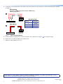
4. Connect four or two speaker wires to the captive screw connector by one of two methods, as shown in the following two examples
(see gure 3).
Number of Wires
per Pole
Maximum
Wire Gauge
1 12 AWG
2 16 AWG
4 18 AWG
Wire Gauge Table
Subwoofer
Power Amplifier
Subwoofer
Power Amplifier
–
+
Double Wiring
Using two 12 AWG wires yields effective 9 AWG wiring,
reducing cable losses.
Single Wiring
1
2
(Black)
(Red)
–
+
(Black)
(Red)
Figure 3. Subwoofer Wiring Methods
5. Insert the captive screw plug into the four-pole receptacle of the subwoofer (see figure 2,
3
on the previous page).
6. Replace the access plate and tighten the retaining screw.
7. Tighten the cable clamp if it was used.
-
 1
1
-
 2
2
-
 3
3
-
 4
4
-
 5
5
-
 6
6
-
 7
7
-
 8
8


Extron SF 10C SUB Manuel utilisateur
- Taper
- Manuel utilisateur
- Ce manuel convient également à
dans d''autres langues
- English: Extron SF 10C SUB User manual
Documents connexes
-
Extron SF 10C SUB Manuel utilisateur
-
-
-
-
Extron CS 26T Plus Manuel utilisateur
-
-
-
Extron SF 26CT LP Manuel utilisateur
-
Extron SF 26CT Manuel utilisateur
-