Pitco 35C+, 90K BTU Manuel utilisateur
- Catégorie
- Friteuses
- Taper
- Manuel utilisateur
Ce manuel convient également à

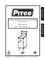
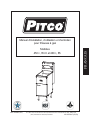
Installation, Operation, and Maintenance Manual
For Gas Fryers
Covering Models
45C+, 35C+ and 40C+, 65
Pitco Frialator, Inc., P.O. Box 501, Jct I-89 & I-93 Concord, NH 03302-0501 • 509 Route 3A, Bow, NH 03304
(603) 225-6684 • FAX (603) 225-8497
L20-072 Rev 7 (01/13)
ENGLISHFRANCAIS

NOTICES
There are three different types of notices that you should be familiar with, a NOTICE, CAUTION,
and WARNING. A NOTICE is a special note used to call attention to a particularly important point.
CAUTION is used to point out a procedure or operation which may cause equipment damage. The
WARNING notice is the most important of the three because it warns of an operation that may cause
personal injury. Please familiarize yourself with your new cooker before operating it and heed the
notices throughout this manual. The WARNINGS are listed below and on the following page for your
review prior to operating the unit.
FOR YOUR SAFETY
DO NOT store or use gasoline or other flammable
vapors or liquids in the vicinity of this or any other
appliance.
WARNING: Improper installation, adjustment, alter-
ation, service or maintenance can cause property dam-
age, injury or death. Read the installation, operating
and maintenance instructions thoroughly before in-
stalling or servicing this equipment.
TO THE PURCHASER
POST IN A PROMINENT LOCATION INSTRUCTIONS TO
BE FOLLOWED IN THE EVENT THAT AN OPERATOR
SMELLS GAS. OBTAIN THIS INFORMATION FROM YOUR
LOCAL GAS SUPPLIER.
THIS MANUAL MUST BE RETAINED FOR FUTURE REFERENCE
ENGLISH

SAFETY SAFETY SAFETY SAFETY SAFETY
SAFETY SAFETY SAFETY SAFETY SAFETY
WARNING
The cooker must be electrically grounded in accordance with local
codes. If local codes do not apply, follow the requirements of
National Code ANSI/NFPA 70-1990.
WARNING
This cooker is equipped with a three prong safety plug. This safety plug
protects operators from electrical shock in the event of an equipment malfunc-
tion. DO NOT remove the grounding (third) prong from this plug.
WARNING
DO NOT use an open flame to check for gas leaks!
WARNING
A cooker that is equipped with casters and a flexible power cord must be
connected to the gas supply with a Quick-Disconnect device. This quick
disconnect must comply with ANSI Z24.41-1989. A restraining cable must
be installed to limit the movement of the cooker.
WARNING
There is an open gas flame inside the cooker. The unit may get hot enough
to set nearby materials on fire. Keep the area around the cooker free from
combustible materials.
WARNING
Ensure that the cooker can get enough air to keep the flame burning correctly.
If the flame is starved for air it can give off dangerous carbon monoxide.
Carbon Monoxide is a clear odorless gas that can cause suffocation and death.
WARNING
Be sure the burner tubes are COMPLETELY covered with water before
lighting the pilot or main burners. If the tubes are exposed, the cooker may
overheat, causing damage to the kettle, creating a fire hazard, and voiding the
warranty.

SAFETY SAFETY SAFETY SAFETY SAFETY
THIS MANUAL MUST BE RETAINED FOR FUTURE REFERENCE
SAFETY SAFETY SAFETY SAFETY SAFETY
WARNING
Carbon monoxide can build up if the flue is blocked. Blocking the flue will
also cause the cooker to overheat. Ensure that minimum clearances specified
in the installation instructions are maintained. DO NOT obstruct the flow of
combustion/ventilation or air opening around the Noodle Cooker. Adequate
clearance around the cooker is necessary for servicing and proper burner
operation. Ensure that you meet the minimum clearances specified in the
installation instructions.
WARNING
The power supply must be disconnected before servicing or cleaning the
appliance.
WARNING
For gas cookers, DO NOT supply the cooker with a gas that is not listed on
the data plate. If you need to convert the cooker to another type of fuel, contact
your dealer.
WARNING
For gas cookers, WAIT five (5) minutes before attempting to relight the pilot.
This allows time for any gas remaining in the cooker to dissipate.
ENGLISH

i
Table of Contents
Section Title Page
Table of Contents ............................................................................................................................................i
List of Tables and Figures ...................................................................................................................................ii
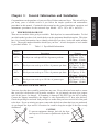
Chapter 1: General Information and Installation ..................................................................................... 1-1
1.1 WHICH FRYER DO I HAVE? .................................................................................................. 1-1
1.2 CHECKING YOUR NEW FRYER............................................................................................ 1-1
1.2.1 Check Your Order ................................................................................................................ 1-2
1.3 ASSEMBLY AND LEVELING ................................................................................................. 1-2
1.3.1 Leg/Caster Installation and Adjustment ............................................................................... 1-2
1.3.2 Assembling Multi Fryer Systems ......................................................................................... 1-3
1.4 INSTALLATION........................................................................................................................ 1-3
1.4.1 Installation Clearances.......................................................................................................... 1-3
1.4.2 Gas Connection .................................................................................................................... 1-3
1.4.2.1 Fuel Types ..................................................................................................................... 1-4
1.4.2.2 Gas Line Connection ..................................................................................................... 1-4
1.4.2.3 Quick Disconnect Gas Connection................................................................................ 1-4
1.4.2.4 Fuel Supply Line Leak and Pressure Testing ................................................................ 1-5
1.4.3 Ventilation and Fire Safety Systems .................................................................................... 1-5
1.5 INITIAL ADJUSTMENTS......................................................................................................... 1-5
1.5.1 Visual Checks....................................................................................................................... 1-6
1.5.2 Burner Ignition Systems ....................................................................................................... 1-6
1.5.2.1 Pilot Flame Adjustment ................................................................................................. 1-7
1.5.3 Main Burner System............................................................................................................. 1-8
1.5.3.1 Gas Line Requirements.................................................................................................. 1-8
1.5.3.2 Burner Adjustment ........................................................................................................ 1-8
1.5.4 Initial Cleaning ..................................................................................................................... 1-9
1.5.5 Thermostat Calibration Check............................................................................................ 1-10
1.5.6 Thermostat Calibration ....................................................................................................... 1-11
Chapter 2: Operating Instructions ............................................................................................................. 2-1
2.1 FILLING THE FRYER............................................................................................................... 2-1
2.1.1 Filling the Fryer With Liquid Shortening ............................................................................. 2-1
2.1.2 Filling the Fryer With Solid Shortening ............................................................................... 2-1
2.2 OPERATING INSTRUCTIONS ................................................................................................ 2-2
2.2.1 Fryer Start-Up....................................................................................................................... 2-2
2.2.2 Melting Solid Shortening...................................................................................................... 2-2
2.2.3 Fryer Shutdown .................................................................................................................... 2-3
2.3 DAILY CLEANING................................................................................................................... 2-3
Chapter 3: Owner Maintenance and Adjustments ................................................................................... 3-1
3.1 WEEKLY FRYER CLEANING (BOIL OUT) .......................................................................... 3-1
3.2 FLUE INSPECTION .................................................................................................................. 3-1
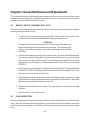
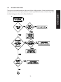
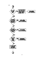
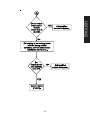
3.3 TROUBLESHOOTING.............................................................................................................. 3-2
ENGLISH

ii
List of Tables and Figures
Table Title Page
1-1 Fryer Model Information ................................................................................. 1-1
1-2 Ventilation and Fire Safety References.............................................................. 1-7
Figure Title Page
1-1 Pilot Assembly, Flame Adjustment................................................................... 1-8
1-2 Gas Valve Showing Location of Pressure Regulator and Pilot Adjusters............... 1-9

1-1
Chapter 1: General Information and Installation
Congratulations on the purchase of your new Pitco Frialator universal fryer. This unit will give
you many years of reliable service if you follow the simple operation and maintenance
procedures in this manual. Contained in this manual are the general installation, operation, and
maintenance procedures for the universal fryer Models 45C+, 35C+ 40C+, and 65C+.
1.1 WHICH FRYER DO I HAVE?
There are two models of this gas fryer available. Each fryer has its own model number. To find
out which model you have, look inside the door at the equipment identification plate. This plate
has a lot of useful information, but to identify which fryer you have, look at the model number
block. The model number identifies which fryer you have. A brief description of each model
is provided inTable 1-1.
Table 1-1 Fryer Model Information
Model
Number
45C+
35C+
40C+
65C+
Description
This fryer can cook up to 85 lbs. of potatoes per hour.
This fryer can cook up to 63 lbs. of potatoes per hour.
This fryer can cook up to 72 lbs. of potatoes per hour.
This fryer can cook up to 120 lbs. of potatoes per
hour.
Features
Frying Area: 14" x 14"
Oil Capacity: 42 lbs.
BTU Input: 122,000
Frying Area: 14" x 14"
Oil Capacity: 35 lbs.
BTU Input: 90,000
Frying Area: 14" x 14"
Oil Capacity: 45 lbs.
BTU Input: 105,000
1.2 CHECKING YOUR NEW FRYER
Your new fryer has been carefully packed into one crate. Every effort has been made to ensure
that your fryer is delivered to you in perfect condition. As you unpack your new fryer, inspect
each of the pieces for damage. If something is damaged, DO NOT sign the bill of lading.
Contact the shipper immediately, the shipper is only responsible for 15 days after delivery.
Check the packing list enclosed with your fryer to ensure that you have received all of the parts
to the fryer. If you are missing any parts, contact the dealer from whom the fryer was purchased.
As you unpack the fryer and it's accessories be careful to keep the weight of the fryer evenly
distributed.
CAUTION
To prevent equipment damage, don't tilt the fryer
onto any two of it's casters or pull the unit by the flue
vents.
ENGLISH
Frying Area: 18" x 18"
Oil Capacity: 65 lbs.
BTU Input: 150,000

1-2
Locate your Pitco Frialator warranty and fill in the serial number of the fryer and the date
received. You will find the serial number on the plate inside the door. Put your warranty card
in a safe place for future reference. DO NOT return the card to Pitco Frialator.
1.2.1 Check Your Order
The crate containing the fryer unit will also contain the following:
(2) Pitco Cleaner Sample
(1) Drain Clean Out Rod
1.3 ASSEMBLY AND LEVELING
When you receive your fryer, it is completely assembled with the possible exception of the legs (or
casters) and the heat shield. In some cases, if you have purchased a multi-fryer unit, you may need to
assemble the system.
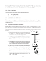
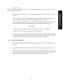
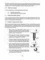
1.3.1 Leg/Caster Installation and Adjustment
Installing the legs and leveling the fryer is done with a 7/16" wrench, socket, and a large pair of water
pump pliers. The legs/casters must be installed to provide the necessary height to meet sanitation
requirements and assure adequate air supply to the burner. Attach the legs by performing the following
procedure.
a. Lay the fryer on its side being careful not to damage the flue
by pulling on it. Protect the outside of the fryer with
cardboard or a drop cloth when laying it down.
b. Attach each leg/caster with the hex head cap screws sup-
plied with the fryer. Each leg/caster requires four 1/4-20 x
5/8" cap screws.
c. Mount the screws from the inside of the fryer with the nut
on the outside. The nuts have lock washers attached to
them, therefore it is not necessary to use lock washers.
d. When all four legs/casters are mounted, stand the unit up
being careful not to put too much weight on any one leg/
caster. Adjust the height and level the fryer by adjusting the
leveling devices on the leg/caster with the water pump
pliers.
e. On units with casters, move the fryer to the desired location
and lock the wheels using the locking devices on the
sides of the casters.
Adjust Here
Lock
Adjust
Here
Un Lock

1-3
1.3.2 Assembling Multi Fryer Systems
If you purchased a multi-fryer unit, it could be shipped in more than one piece. To assemble the unit
follow the instructions below.
a. Unpack the units and move them close together. Remove the front panels and both heat
shields from the fryers.
b. There are five joining strips to be attached to the units to make them into one system. These
strips are attached in the rear, front, upper front, and the forward and rear caster mount. Use
the screws supplied with your system to attach the strips. Secure them tightly to each unit.
c. Replace the heat shield and front panels to complete the system assembly.
1.4 INSTALLATION
Although it is possible for you to install and set up your new fryer, it is STRONGLY recommended
that you have it done by qualified professionals. The professionals that install your new fryer will know
the local building codes and ensure that your installation is safe.
WARNING
The fryer must be properly restrained to prevent movement or tipping. This
restraint must prevent the fryer from movements that would splash hot liquids
on personnel. This restraint may be any means (alcove installation, adequate
ties, or battery installation).
1.4.1 Installation Clearances
The fryer needs clearance around it for proper operation. Adequate clearances allow for servicing and
proper burner operation. The clearances shown below are for cooker installation in combustible and
non-combustible construction.
Combustible Non-Combustible
Construction Construction
Back 6" 0"
Sides 6" 0"
Floor - Combustible 6" 6"
1.4.2 Gas Connection
Your fryer will give you peak performance when the gas supply line is of sufficient size to provide the
correct gas flow. The gas line must be installed to meet the local building codes or National
ENGLISH

1-4
Fuel Gas Code (NFPA 54-Latest Edition) and ANSI Z223.1-Latest Edition Latest Edition. In
Canada, install the fryer in accordance with CAN/CGA-B149.1 or .2 and local codes. Gas line
sizing requirements can be determined by your local gas company by referring to National Fuel
Gas Code, Appendix C, Table C-4 (natural gas) and Table C-16 (propane). The gas line needs
to be large enough to supply the necessary amount of fuel to all appliances without losing
pressure to any appliance. Other factors that are used to determine the piping requirements
are BTU requirements of the appliances being connected and the length of pipe between the
meter (main shut off) and the appliances.
WARNING
NEVER supply the fryer with a gas that is not indicated on the data plate. Using
the incorrect gas type will cause improper operation. If you need to convert the
fryer to another type of fuel, contact your dealer.
1.4.2.1 Fuel Types - Each fryer is equipped to work with one type of fuel. The type of fuel with
which the appliance is intended to operate is stamped on the data plate attached to the inside of the door.
WARNING
DO NOT use an open flame to check for gas leaks!
1.4.2.2 Gas Line Connection - Connect the fryer to the gas supply line with a connector that
complies with the Standard for Connectors for Movable Gas Appliances (ANSI Z21.69-Latest
Edition). If you are installing a fryer with casters use a quick disconnect refer to the Quick Disconnect
installation instruction, 1.4.2.3. Connect the gas line to the fryer using a pipe joint sealant that is resistant
to liquefied petroleum. If the fryer was disconnected during the fuel line testing, use a solution of soap
and water to leak test the new connection.
NOTICE
NEVER use an adaptor to make a smaller gas supply line fit the cooker
connection. This may not allow proper gas flow for optimum burner operation,
resulting in poor cooker performance.
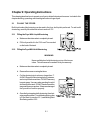
1.4.2.3 Quick Disconnect Gas Connection - Gas fryers equipped with casters must be installed
with connectors that comply with the Standard for Connectors for Movable Gas Appliances, ANSI
Z21.69-Latest Edition, and Addenda Z21.69A-Latest Edition. This connection should include a
quick disconnect device that complies with the Standard for Quick Disconnect Devices for Use
With Gas Fuel , ANSI Z21.41-Latest Edition. When installing a quick disconnect you must also
install a means for limiting the movement of the fryer. This device will prevent the gas line or the
quick disconnect from being strained. The restraining device should be attached to the cooker on
the back panel as shown in the illustration. The quick disconnect, hose, and restraining device can
be obtained from your dealer.

1-5
1.4.2.4 Fuel Supply Line Leak and Pressure Testing - The fuel supply system must be tested before
the fryer is used. If the fuel line is going to be tested at a pressure greater than (>)1/2 PSIG (3.45 kPa),
make sure that the fryer is disconnected from the fuel line. If the fuel line is to be tested at a pressure
equal to or less than (<) 1/2 PSIG (3.45 kPa), the fryer can be connected but the unit's gas valve must
be shut. Test all gas line connections for leaks with a solution of soap and water when pressure is
applied.
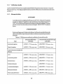
1.4.3 Ventilation and Fire Safety Systems
Your new fryer must have proper ventilation to function safely and properly. Exhaust gas temperatures
can reach as high as 1200°F. Therefore, it is very important to install a fire safety system. Your
ventilation system should be designed to allow for easy cleaning. Frequent cleaning of the ventilation
system and the fryer will reduce the chances of fire. Table 1-2 provides a list of reference documents
that provide guidance on ventilation and fire safety systems. This table is not necessarily complete.
Additional information can be obtained from the American Gas Association, 8501 East Pleasant Valley
Road, Cleveland, OH 44131.
Excessive ventilation causes drafts, which will interfere with the proper operation of the pilot and
the burner. Leave at least 18 inches of open space between the fryer's flue vent opening and the
intake of the exhaust hood.
CAUTION
Ensure that your ventilation system does not cause a down draft at the fryer's
flue opening. Down drafts will not allow the fryer to exhaust properly and will
cause overheating which may cause permanent damage. Damage caused by
down drafts will not be covered under equipment warranty. NEVER allow
anything to obstruct the flow of combustibles or ventilation exiting from the
fryer flue. DO NOT put anything on top of the flue area.
NOTICE
NEVER connect the blower directly to the flue openings. The direct flow of
air will cause poor temperature recovery, poor ignition, inefficient operation of
the fryer, and could extinguish the pilot.
1.5 INITIAL ADJUSTMENTS
After your fryer has been installed as described in section 1.4, it needs to be adjusted to ensure that it
will perform as designed. These adjustments must be performed by a qualified person. To perform
these adjustment the following tools will be needed:
• Manometer (low pressure gauge) • Digital Thermometer (Temperature probe)
• DC Millivolt Meter
ENGLISH

1-6
1.5.1 Visual Checks
After the fryer is in its permanent location, lock the casters and check for levelness. Any additional
leveling that is necessary can be performed as described in section 1.3.
1.5.2 Burner Ignition Systems
CAUTION
Before going any further, fill the fryer with WATER. Water is used for the
installation adjustments because the temperature will never exceed 212°F
(100°C) thereby allowing plenty of adjustment time. Never let the water level
go below the MIN LEVEL mark on the rear of the tank.
WARNING
There is an open flame inside the fryer. The unit may get hot enough to set near
by materials on fire. Keep the area around the fryer free from combus-
Topic
Grease Extractor
Ventilation Hood
Type of Fire Extinguishers
and Detection Equipment
CO
2
Dry Chemical
Water
Foam
Sprinklers
Smoke Detectors
Fire Detection Thermostats
National Fuel Gas Code
Document
ANSI/NFPA 96-Latest Edition
ANSI/NFPA 96-Latest Edition
ANSI/NFPA 12-Latest Edition
ANSI/NFPA 17-Latest Edition
ANSI/NFPA 13-Latest Edition
ANSI/NFPA 11-Latest Edition
ANSI/NFPA 13-Latest Edition
ANSI/FPA 72B-Latest Edition
ANSI/FPA 72B-Latest Edition
Underwriters Laboratory
Document
ANSI/UL 710-Latest Edition
ANSI/UL 705-Latest Edition
ANSI/UL 154-Latest Edition
ANSI/UL 299-Latest Edition
ANSI/UL 626-Latest Edition
ANSI/UL 199-Latest Edition
ANSI/UL 268-Latest Edition
ANSI/UL 521-Latest Edition
Table 1-2. Ventilation and Fire Safety References

1-7
tibles.
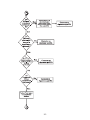
To light the pilot light, refer to these instructions.
WARNING
Wait 5 minutes before attempting to relight the pilot to allow for any gas in the
fryer to dissipate.
a. Open the gas supply valves to the fryer.
b. Open the fryer's door to gain access to the controls. Turn the thermostat control knob
counterclockwise to the OFF position.
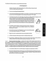
c. Turn the Unitrol valve knob to the PILOT position and push in on the
knob. Hold the knob in for approximately one minute to purge the air
out of the line. Hold a flame to the pilot light until the pilot ignites. This
may take a little while the first time you light the fryer because of air
in the lines. Once lit, hold the knob in for approximately 60 seconds
and then release.
d. If the pilot goes out wait 5 minutes and repeat step c. If after three
tries the pilot will not remain lit, refer to the operator troubleshoot-
ing section of this manual.
e. Turn the Unitrol valve knob counterclockwise to the ON position.
f. Set the thermostat control knob to the desired temperature set-
ting.
g. The main burner will light and be controlled by the thermostat.
h. To completely shut down the fryer, turn the Unitrol valve knob to pilot, push in and
continue turning to OFF.
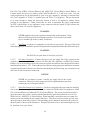
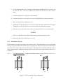
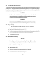
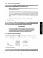
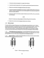
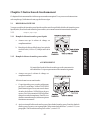
1.5.2.1 Pilot Flame Adjustment - The pilot flame should be adjusted to produce the proper millivolt
output from the pilot sensing device. Millivolt output for the thermopile should be between 300 and
500 millivolts. This procedure is only necessary on the manual pilot ignition system. Figure 1-1 shows
the pilot assembly with examples of the incorrect and correct pilot size. Example A illustrates a pilot
flame size that is too small to produce sufficient millivolt output. Example B is the correct size for proper
millivolt output.
a. This test requires a DC millivolt meter set to a scale of 0-1000mv.
ENGLISH

1-8
b. Locate the thermopile wires coming from the thermostat/High Limit box going to the
gas shut off valve. The wire insulation size decreases near the gas valve connec-
tions.
c. Connect the negative (-) test probe to pilot bracket.
d. Connect the positive (+) test probe to to one of the High Limit terminal connections
e. Remove the pilot flame adjustment cover.
f. Turning the flame adjusting screw clockwise lowers the flame and the millivolt output.
Turning the screw counterclockwise increases flame size and millivolt output.
g. Rotate the screw in the direction to achieve a reading of 400 ±50 mv for thermopiles.
NOTICE
Allow 3 to 5 minutes between flame adjustments to allow the reading to settle.
h. Replace the pilot flame adjusting screw cover.
1.5.3 Main Burner System
For the burners to work, the gas supply valve must be open. The main burner receives gas from the
main gas supply through the thermostatically controlled valve. When the thermostat is turned up the
gas control valve opens. The pilot ignites the burners. The burner flame should be adjusted at the air
collar (at the bottom of the burner) so the the flame are a soft blue color without lifting off the face of
the burner.
1.5.3.1 Gas Line Requirements - A properly installed gas supply system will deliver 7.0 ±2.0" w.c.
Figure 1-1 Pilot Assembly, Flame Adjustment
BA

1-9
natural gas (12.0 ±2.0" w.c. LP) to all appliances connected to the line, operating at full
demand.
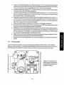
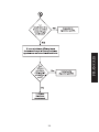
1.5.3.2 Burner Adjustment - The burners must be adjusted to deliver optimum flame. Adjust the
burner flame using the following procedure.
a. Ensure that the Unitrol valve knob is in the OFF position. Remove the manifold pressure
tap plug and connect an accurate pressure gauge (range of 0-16" w.c. in 0.1" increments)
or manometer.
b. Light the pilot burner (see 1.5.2) for the unit being tested and adjust the thermostat to light
the main burners.
c. The installed pressure gauge reading should be the same, ±0.1", as that marked on the data
plate inside the door. If the pressure is correct go to step e, if not, adjust the pressure.
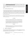
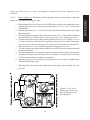
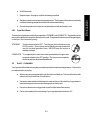
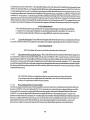
d. To adjust the pressure, remove the regulator adjustment screw cover (see Figure 1-3). Use
a flat tip screwdriver to adjust the screw until the proper pressure is reached. Turning the
screw clockwise will increase the pressure, counterclockwise will decrease the pressure.
e. When the pressure is correct, install the regulator adjustment screw cover.
f. To remove the pressure gauge, turn gas control valve to OFF. Remove the gauge and install
the pressure tap plug.
g. Now that the pressure is set for proper operation, set the main burner flame. Unlock the air
collars by loosening the set screw for the collars. See Figure 5. Turn the Unitrol valve knob
to ON and turn thermostat to light the main burners.
h. Adjust the shape and size by raising or lowering the air collars to achieve a soft blue flame
with well defined inner cones.
i. When the flames have been properly adjusted, lock the collars in place with the set screw
provided.
Figure 1-2 Gas Valve
Showing Location of the
Pressure Regulator and
Pilot Adjusters
ENGLISH

1-10
1.5.4 Initial Cleaning
When the fryer is shipped, many of its parts are covered with a thin coat of oil for protection.
Before the fryer is ready for cooking it must be cleaned. This will remove the oil coating and
any foreign matter that may have accumulated during storage and shipment. Perform the
cleaning as described below.
a . Fill the tank with water and add one packet of Pitco fryer cleaner or a mild detergent.
b. Turn the fryer on and set the thermostat to 200°F. Allow the fryer to heat for 15 minutes.
NOTICE
Do not leave the fryer unattended during cleaning. Never let the water level go
below the "Min Level" mark on the back of the tank.
c. Using the fryer cleaning brush, scrub the inside of the fryer to remove protective coating.
d. When cleaning is complete, turn off the fryer main burners and turn the Unitrol valve knob
to the PILOT position. Drain the water into a container suitable for hot water and dispose
of it.
e. When the tank has cooled, rinse it thoroughly with cool water. Continue to rinse the tank
until the cleaner has been rinsed, thoroughly from the tank.
f. Using a clean dry cloth, wipe out all of the water. Be very thorough removing the water,
because any residual water will cause hot oil to splatter out of the fryer.
CAUTION
Mild steel tanks must be wiped down/coated with oil to keep the tank from
rusting.
g. Now that the tank is clean, you are ready to fill and operate the fryer. Refer to 2.1 for
instructions on adding shortening to the fryer.
1.5.5 Thermostat Calibration Check
NOTICE
Thermostat calibration requires that the temperature of the fryer be raised above
boiling. Therefore, you will need to drain the water from the fryer and fill it with
oil. Before removing the water, perform the initial cleaning of the fryer.
Cleaning the fryer now will prevent you from having to drain the oil and refill

1-11
with water later.
Filling the fryer with oil is described in 2.1. To perform the calibration check detailed below you will
need a digital thermometer.
a. Place the tip of the thermometer in the shortening approximately 1" above the temperature
sensors.
b. Set the thermostat at 325°F and wait for the temperature reading on the thermometer to rise.
As the temperature rises toward 325°F watch the thermometer closely.
c. If the shortening temperature reaches 350°F and the burners DO NOT turn off, turn the
thermostat down. Keep lowering the thermostat setting until the burners go out.
CAUTION
If the burners do not turn off at the lowest thermostat setting, the thermostat
could be defective. Contact your representative immediately.
d. Let the fryer cycle 4 to 6 times before checking the temperature. Compare the thermometer
temperature against the thermostat setting. If the values are more than 5°F apart, calibrate
the thermostat using the appropriate calibration procedure in this manual.
1.5.6 Thermostat Calibration
a. Place the tip of the thermometer in the shortening approximately 1" above the temperature
sensors.
b. Set the Thermostat to 325°F and wait for the temperature reading on the thermometer to rise.
c. Let the fryer cycle 4 to 6 times to ensure that the temperature has stabilized. Compare the
thermometer temperature against the thermostat setting. If the values are more than 5°F
apart, calibrate the thermostat using the appropriate calibration procedure.
ENGLISH

1-2
snoitcurtsnI gnitarepO :2 retpahC
siht ni dedulcnI .ecnamrofrep tseb eht niatbo ot reyrf ruoy etarepo ot woh sebircsed retpahc sihT
.sreyrf sag rof snoitcurtsni gninaelc dna ,gnitarepo ,gnillif era retpahc
1.2 REYRF EHT GNILLIF
dilos tlem oT .derreferp si diuqil tub ,reyrf eht ni desu eb nac gninetrohs dilos dna diuqil htoB
.2.2.2 noitces ni noitcurtsni eht wollof ylluferac ,gninetrohs
1.1.2 gninetrohS diuqiL htiW reyrF eht gnilliF
.a .desolc yletelpmoc si evlav niard eht erus ekaM
.b dekram enil "leveL liO" eht ot lio htiw reyrf eht lliF
.knat eht fo kcab eht no
2.1.2 gninetrohS diloS htiW reyrF eht gnilliF
GNINRAW
renrub eht fo pot no gninetrohs dilos fo skcolb tlem reveN
.ytnarraw ruoy diov lliw dna erif a esuac lliw sihT .sebut
.a .desolc yletelpmoc si evlav niard eht erus ekaM
.b .sebut eht gnirevoc neercs eht evomeR
.c ."1 naht regral on sebuc otni gninetrohs eht tuC
,neewteb ,woleb gninetrohs eht kcap SYAWLA
yna evael TON OD .sebut renrub eht fo pot no dna
dilos eht gnikcap nehw erac esU .spag ria egral
eht kaerb ro dneb TON OD .knat eht ni gninetrohs
degamad era eseht fI .seborp rosnes erutarepmet
.ylreporp noitcnuf ton lliw reyrf eht
.d -trohs eht ,gninetrohs htiw dekcap si reyrf eht ecnO
refer ,gninetrohs eht tlem oT .detlem eb tsum gnine
diloS gnitleM dna ,1.2.2 noitces ,pU-tratS reyrF ot
.2.2.2 noitces ,gninetrohS
HSILGNE

2-2
2.2 SNOITCURTSNI GNITAREPO
doof eht rof snoitcurtsni noitaraperp eht wollof ,tseb yrev eht tuo semoc syawla doof eht erusne oT
tsal lliw gninetrohs tseb ehT .sdoof deirf tseb eht sekam gninetrohs tseb eht gnisU .gnikooc era uoy
eb dluohs gninetrohs eht esu ni ton nehW .yenom uoy evas dna gninetrohs edarg rewol naht regnol
.noitanimatnoc tneverp ot derevoc dna delooc
NOITUAC
latnedicca tneverp ot secived gniniartser gnisu dellatsni neeb sah reyrf ehT
diuqil toh sah ti nehw reyrf eht evom ot tpmetta ton oD .tnemevom ro gnippit
.snrub ereves esuac nac sdiuqil toh gnihsalpS .ti ni
GNINRAW
.gninetrohs toh morf yawa sdiuqil peeK .xim TON OD gninetrohs dna retaW
.gniliob tneloiv esuac lliw gninetrohs toh eht otni doof nezorf diuqil gnipporD
1.2.2 pU-tratS reyrF
!LIO HTIW GNILLIF TUOHTIW REYRF TRATS TON OD
.a .2.5.1 noitces ni debircsed sa thgil tolip eht thgiL
.b sihT .gnittes erutarepmet derised eht ot )tatsomreht( bonk lortnoc erutarepmet eht nruT
.lenap lortnoc tnorf eht no ro srood tnorf eht dniheb detacol si bonk
.c .thgil lliw srenrub niam ehT
2.2.2 gninetrohS diloS gnitleM
ECITON
ylluferac hctaW .reyrf eht fo gnilcyc seriuqer woleb erudecorp gnitlem ehT
,siht tneverp oT .gnihcrocs si gninetrohs eht ,deciton si ekoms fI .ekoms rof
.no srenrub eht evael uoy emit eht esaerced
.a .noitisop NO ni evlav lortinU eht ecalP
.b .F°051 ot tatsomreht teS
.c .sdnoces )4( ruof yletamixorppa rof erif ot srenrub niam wollA
.d .tuo og srenrub niam litnu nwod tatsomreht nruT

3-2
.e .sdnoces 03 tiaW
.f .detlem si gninetrohs eht litnu .e hguorht .c spets taepeR
.g yltnatsnoc no niamer lliw srenrub ehT .erutarepmet gnitarepo lamron ot tatsomreht teS
.gnittes tatsomreht eht sehcaer erutarepmet gninetrohs eht litnu
.h .esu ot ydaer dna yllamron gnitarepo won si reyrf eht ,erutarepmet ta ecnO
3.2.2 nwoD-tuhS reyrF
edom ybdnats ehT .ETELPMOC dna YBDNATS ,noitarepo reyrf fo sedom nwodtuhs owt era erehT
ylppus sag eht ffo snrut nwodtuhs etelpmoC .elcyc ot srenrub niam s'reyrf eht rof ytiliba eht sevomer
:yb reyrf eht nwod tuhS .reyrf eht ot
YBDNATS eht ot esiwkcolc evlav sag eht nruT .FFO ot tatsomreht eht nruT
siht niamer nac dna ybdnatS ni won si rekooc ehT .noitisop TOLIP
ni rekooc eht evael REVEN .emit fo sdoirep feirb ylno rof yaw
.thginrevo ybdnats
ETELPMOC evlav sag eht nrut dna hsup ,rekooc eht nwod tuhs yletelpmoc oT
yletelpmoc won si reyrf ehT .noitisop FFO eht ot esiwkcolcretnuoc
.deretlif dna denaelc eb nac dna nwod tuhs
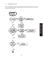
3.2 GNINAELC YLIAD
eht mrofreP .ecnaraeppa dna ecnamrofrep kaep niatniam ot yad yreve denaelc eb dluohs reyrf ruoY
.yad yreve woleb serudecorp
.a htiw enod eb dluohs sihT .reyrf eht fo roiretxe eht otno sllips taht gninetrohs yna pu epiW
.mraw llits si lio eht elihw htolc tfos naelc a
.b ni retaw teg ot ton luferac eB .secafrus naelc ot tnegreted dlim a htiw retaw mraw esU
.knat yrf eht morf tnegreted yna evomer ot dna gninetrohs eht
.c .yrassecen fi sniats naelc ot dap ro redwop gniruocs evisarba-non a esU
.d .2.3 noitces ni debircsed reyrf ruoy fo gninaelc tuo liob ylkeew eht mrofreP
HSILGNE
La page est en cours de chargement...
La page est en cours de chargement...
La page est en cours de chargement...
La page est en cours de chargement...
La page est en cours de chargement...
La page est en cours de chargement...
La page est en cours de chargement...
La page est en cours de chargement...
La page est en cours de chargement...
La page est en cours de chargement...
La page est en cours de chargement...
La page est en cours de chargement...
La page est en cours de chargement...
La page est en cours de chargement...
La page est en cours de chargement...
La page est en cours de chargement...
La page est en cours de chargement...
La page est en cours de chargement...
La page est en cours de chargement...
La page est en cours de chargement...
La page est en cours de chargement...
La page est en cours de chargement...
La page est en cours de chargement...
La page est en cours de chargement...
La page est en cours de chargement...
La page est en cours de chargement...
La page est en cours de chargement...
-
 1
1
-
 2
2
-
 3
3
-
 4
4
-
 5
5
-
 6
6
-
 7
7
-
 8
8
-
 9
9
-
 10
10
-
 11
11
-
 12
12
-
 13
13
-
 14
14
-
 15
15
-
 16
16
-
 17
17
-
 18
18
-
 19
19
-
 20
20
-
 21
21
-
 22
22
-
 23
23
-
 24
24
-
 25
25
-
 26
26
-
 27
27
-
 28
28
-
 29
29
-
 30
30
-
 31
31
-
 32
32
-
 33
33
-
 34
34
-
 35
35
-
 36
36
-
 37
37
-
 38
38
-
 39
39
-
 40
40
-
 41
41
-
 42
42
-
 43
43
-
 44
44
-
 45
45
-
 46
46
-
 47
47


Pitco 35C+, 90K BTU Manuel utilisateur
- Catégorie
- Friteuses
- Taper
- Manuel utilisateur
- Ce manuel convient également à
dans d''autres langues
- English: Pitco 35C+, 90K BTU User manual
Documents connexes
-
Pitco Frialator 35C+ Manuel utilisateur
-
Pitco SG14 Manuel utilisateur
-
Pitco Solofilter SFSG14, 110K BTU, Full Vat 40-50lbs. Oil Capacity Le manuel du propriétaire
-
Pitco SGM18 w/Filter System Manuel utilisateur
-
-
Pitco 18F Le manuel du propriétaire
-
Pitco Frialator E7 Manuel utilisateur
Autres documents
-
-
Magic Chef MCCGF40A-P Manuel utilisateur
-
Garland C836-1-35F Manuel utilisateur
-
Vulcan VK45 Le manuel du propriétaire
-
Vulcan VHG75 Le manuel du propriétaire
-
Vulcan LG300 Le manuel du propriétaire
-
-
Vulcan VEG50 Le manuel du propriétaire