CHAUVET DJ Derby X Manuel utilisateur
- Catégorie
- Stroboscopes
- Taper
- Manuel utilisateur

5200 NW 108th Avenue, Sunrise, FL 33351 U.S.A.
(800) 762-1084 – (954) 929-1115
FAX (954) 929-5560
www.chauvetlighting.com
Derby X™
USER MANUAL
Snapshot
OK on Dimmer
Outdoor OK
Sound-Activated
DMX512
Master/Slave
Autoswitching
Transformer
Replaceable Fuse
User Serviceable

Derby X™ User Manual 2
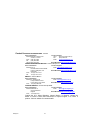
TABLE OF CONTENTS
1. Before You Begin ...................................................................................................................................... 5
WHAT IS INCLUDED ............................................................................................................................................................................... 5
UNPACKING INSTRUCTIONS .................................................................................................................................................................... 5
AC POWER........................................................................................................................................................................................... 5
SAFETY NOTES ..................................................................................................................................................................................... 6
2. Introduction ............................................................................................................................................... 7
FEATURES ............................................................................................................................................................................................ 7
DMX CHANNEL SUMMARY ..................................................................................................................................................................... 7
PRODUCT OVERVIEW............................................................................................................................................................................. 7
3. Setup .......................................................................................................................................................... 8
FUSE REPLACEMENT ............................................................................................................................................................................. 8
PRODUCT LINKING ................................................................................................................................................................................. 8
Master/Slave Product Linking .................................................................................................................................... 8
MOUNTING............................................................................................................................................................................................ 9
Orientation ................................................................................................................................................................ 9
Rigging ..................................................................................................................................................................... 9
STACKING ........................................................................................................................................................................................... 10
4. Operating Instructions.............................................................................................................................11
Standalone Mode (Sound-Active): ........................................................................................................................... 11
Master/Slave Mode (Master Sound): ....................................................................................................................... 11
DMX Mode .............................................................................................................................................................. 11
DMX CHANNEL VALUES ...................................................................................................................................................................... 12
Setting the Starting Address .................................................................................................................................... 13
DMX Quick Reference Chart ................................................................................................................................... 14
TROUBLESHOOTING GUIDE .................................................................................................................................................................. 15
5. Appendix ...................................................................................................................................................16
GENERAL MAINTENANCE...................................................................................................................................................................... 16
RETURNS PROCEDURE ........................................................................................................................................................................ 16
CLAIMS .............................................................................................................................................................................................. 16
TECHNICAL SPECIFICATIONS ................................................................................................................................................................ 17
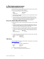
1. Antes de empezar ....................................................................................................................................18
QUÉ VA INCLUIDO ................................................................................................................................................................................ 18
INSTRUCCIONES DE DESEMBALAJE ........................................................................................................................................................ 18
CORRIENTE ALTERNA ........................................................................................................................................................................... 18
NOTAS DE SEGURIDAD ......................................................................................................................................................................... 19
2. Introducción .............................................................................................................................................20
CARACTERÍSTICAS............................................................................................................................................................................... 20
RESUMEN DE CANALES DMX ............................................................................................................................................................... 20
VISIÓN GENERAL DEL PRODUCTO .......................................................................................................................................................... 20
3. Instalación ................................................................................................................................................21
SUSTITUCIÓN DEL FUSIBLE ................................................................................................................................................................... 21
ENLACE DEL PRODUCTO ....................................................................................................................................................................... 21
Enlace del producto en Maestro/Esclavo ................................................................................................................ 21
MONTAJE ........................................................................................................................................................................................... 22
Orientación ............................................................................................................................................................. 22
Instalación de aparejos ........................................................................................................................................... 22
APILAMIENTO ...................................................................................................................................................................................... 23
4. Instrucciones de funcionamiento ...........................................................................................................24
Modo Independiente (Activo por sonido): ................................................................................................................ 24
Modo Maestro/Esclavo (Sonido maestro): ............................................................................................................... 24

Derby X™ User Manual 3
Modo DMX .............................................................................................................................................................. 24
VALORES CANALES DMX ..................................................................................................................................................................... 25
Configurar la dirección de inicio .............................................................................................................................. 26
Tabla de referencia rápida DMX.............................................................................................................................. 27
GUÍA DE RESOLUCIÓN DE PROBLEMAS ................................................................................................................................................... 28
5. Apéndice ...................................................................................................................................................29
MANTENIMIENTO GENERAL ................................................................................................................................................................... 29
PROCEDIMIENTO DE DEVOLUCIÓN ......................................................................................................................................................... 30
RECLAMACIONES ................................................................................................................................................................................. 30
ESPECIFICACIONES TÉCNICAS .............................................................................................................................................................. 31
1. Avant de commencer ...............................................................................................................................32
CONTENU DE L'EMBALLAGE .................................................................................................................................................................. 32
INSTRUCTIONS DE DEBALLAGE .............................................................................................................................................................. 32
ALIMENTATION SECTEUR ...................................................................................................................................................................... 32
INSTRUCTIONS DE SECURITE................................................................................................................................................................. 33
2. Introduction ..............................................................................................................................................34
CARACTERISTIQUES ............................................................................................................................................................................ 34
RESUME DES CANAUX DMX ................................................................................................................................................................. 34
Vue d'ensemble du produit .........................................................................................................................34
3. Installation ................................................................................................................................................35
REMPLACEMENT DU FUSIBLE ................................................................................................................................................................ 35
RACCORDEMENT DE L'APPAREIL ........................................................................................................................................................... 35
Câblage pour données ............................................................................................................................................ 35
Câble de données DMX .......................................................................................................................................... 36
Raccordement de l'appareil en maître/esclave ........................................................................................................ 36
MONTAGE ........................................................................................................................................................................................... 37
Orientation .............................................................................................................................................................. 37
Accrochage ............................................................................................................................................................. 37
EMPILAGE ........................................................................................................................................................................................... 38
4. Instructions d'emploi ...............................................................................................................................39
FONCTIONNEMENT .............................................................................................................................................................................. 39
Mode autonome (activation par le son): .................................................................................................................. 39
Mode maître/esclave (maître activé par le son): ...................................................................................................... 39
Mode DMX .............................................................................................................................................................. 40
VALEURS DES CANAUX DMX ................................................................................................................................................................ 40
GUIDE GENERAL DE DEPANNAGE ........................................................................................................................................................... 41
5. Appendice .................................................................................................................................................42
MAINTENANCE GENERALE .................................................................................................................................................................... 42
PROCEDURE DE RETOUR ...................................................................................................................................................................... 42
RECLAMATIONS ................................................................................................................................................................................... 42
CARACTERISTIQUES TECHNIQUES ......................................................................................................................................................... 43
1. Erste Schritte ............................................................................................................................................44
PACKUNGSINHALT ............................................................................................................................................................................... 44
ANWEISUNGEN FÜR DAS AUSPACKEN .................................................................................................................................................... 44
WECHSELSTROM ................................................................................................................................................................................. 44
SICHERHEITSHINWEISE ........................................................................................................................................................................ 45
2. Einleitung ..................................................................................................................................................46
EIGENSCHAFTEN ................................................................................................................................................................................. 46
ÜBERSICHT DMX-KANAL-ZUWEISUNG .................................................................................................................................................. 46
PRODUKTÜBERBLICK ........................................................................................................................................................................... 46
3. Einrichten des Geräts ..............................................................................................................................47
AUSWECHSELN DER SICHERUNG .......................................................................................................................................................... 47

Derby X™ User Manual 4
SERIENSCHALTUNG DER GERÄTE ......................................................................................................................................................... 47
Serienschaltung der Geräte per Master/Slave ......................................................................................................... 47
MONTAGE ........................................................................................................................................................................................... 48
Montagerichtung ..................................................................................................................................................... 48
Hängende Montage ................................................................................................................................................ 48
STAPELN ............................................................................................................................................................................................ 49
4. Betriebsanweisungen ..............................................................................................................................50
Stand-alone-Modus (Musiksteuerung): .................................................................................................................... 50
Master/Slave-Modus (Master-Musiksteuerung) ....................................................................................................... 50
DMX-Modus ............................................................................................................................................................ 50
DMX-KANAL-WERTE .......................................................................................................................................................................... 51
Einrichten der Startadresse ..................................................................................................................................... 52
DMX-Schnellübersichtstabelle ................................................................................................................................ 53
FEHLERBEHEBUNG .............................................................................................................................................................................. 54
5. Anhang......................................................................................................................................................55
ALLGEMEINE WARTUNGSARBEITEN ....................................................................................................................................................... 55
RÜCKSENDUNGEN ............................................................................................................................................................................... 56
SCHADENSMELDUNG ........................................................................................................................................................................... 56
TECHNISCHE DATEN ............................................................................................................................................................................ 57
1. Voordat u begint ......................................................................................................................................58
WAT IS ER INBEGREPEN ....................................................................................................................................................................... 58
UITPAKINSTRUCTIES ............................................................................................................................................................................ 58
AC-STROOM ....................................................................................................................................................................................... 58
VEILIGHEIDSVOORSCHRIFTEN ............................................................................................................................................................... 59
2. Inleiding ....................................................................................................................................................60
EIGENSCHAPPEN ................................................................................................................................................................................. 60
SAMENVATTING DMX-KANAAL .............................................................................................................................................................. 60
PRODUCTOVERZICHT ........................................................................................................................................................................... 60
3. Instelling ...................................................................................................................................................61
VERVANGEN VAN DE ZEKERING ............................................................................................................................................................. 61
KOPPELING VAN PRODUCTEN ................................................................................................................................................................ 61
Master/slave koppeling van producten .................................................................................................................... 61
MONTAGE ........................................................................................................................................................................................... 62
Oriëntatie ................................................................................................................................................................ 62
Opbouw .................................................................................................................................................................. 62
STAPELEN .......................................................................................................................................................................................... 63
4. GEBRUIKSINSTRUCTIES .................................................................................................................................................................... 64
Losstaande modus (geluidsactief): .......................................................................................................................... 64
Master/slave-mode (mastergeluid): ......................................................................................................................... 64
DMX-modus ............................................................................................................................................................ 64
DMX-KANAALWAARDEN ....................................................................................................................................................................... 65
Instellen van het startadres ..................................................................................................................................... 66
Beknopt referentiediagram DMX ............................................................................................................................. 67
GIDS VOOR PROBLEEMOPLOSSING ........................................................................................................................................................ 68
5. Bijlage .......................................................................................................................................................69
ALGEMEEN ONDERHOUD ...................................................................................................................................................................... 69
RETOURPROCEDURE ........................................................................................................................................................................... 70
CLAIMS .............................................................................................................................................................................................. 70
TECHNISCHE SPECIFICATIES ................................................................................................................................................................ 70

Derby X™ User Manual 5
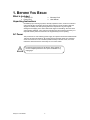
1. BEFORE YOU BEGIN
What Is Included
1 x Derby X™
Power Cord
Warranty Card
User Manual
Unpacking Instructions
Immediately upon receiving a product, carefully unpack the carton, check the contents to
ensure that all parts are present, and have been received in good condition. Notify the
shipper immediately and retain packing material for inspection if any parts appear
damaged from shipping or the carton itself shows signs of mishandling. Save the carton
and all packing materials. In the event that a product must be returned to the factory, it is
important that the product be returned in the original factory box and packing.
AC Power
This product has an auto-switching power supply. This product will accommodate between
100 VAC and 240 VAC 50/60 Hz. All products must be powered directly off a switched
circuit and cannot be run off a rheostat (variable resistor) or dimmer circuit, even if the
rheostat or dimmer channel is used solely for a 0 to 100% switch.
To eliminate wear and improve its lifespan, during periods of
non-use completely disconnect from power via breaker or by
unplugging it.

Derby X™ User Manual 6
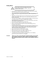
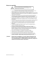
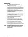
Safety Notes
• Please keep this User Manual for future consultation. If you sell the product to another
user, be sure that they also receive this instruction booklet.
• Always make sure that you are connecting to the proper voltage, and that the line voltage
you are connecting to is not higher than that stated on the decal or rear panel of the
product.
• This product is intended for indoor use only! To prevent risk of fire or shock, do not expose
product to rain or moisture. Make sure there are no flammable materials close to the
product while operating.
• The product must be installed in a location with adequate ventilation, at least 20in (50cm)
from adjacent surfaces. Be sure that no ventilation slots are blocked.
• Always disconnect from power source before servicing or replacing lamp or fuse and be
sure to replace with same lamp source.
• Secure product to fastening device using a safety chain.
• Never carry the product solely by its head. Use its carrying handles.
• Maximum ambient temperature (Ta) is 104 °F (40 °C). Do not operate product at
temperatures higher than this.
• In the event of a serious operating problem, stop using the product immediately. Never try
to repair the product by yourself. Repairs carried out by unskilled people can lead to
damage or malfunction. Please contact the nearest authorized technical assistance
center. Always use the same type spare parts.
• Never connect the device to a dimmer pack or rheostat.
• Make sure the power cord is never crimped or damaged.
• Never disconnect the power cord by pulling or tugging on the cord.
• Avoid direct eye exposure to the light source while it is on.
• To eliminate wear and improve its lifespan, during periods of non-use completely
disconnect from power via breaker or by unplugging it.
Caution! There are no-user serviceable parts inside the product. Do not open
the housing or attempt any repairs yourself. In the unlikely event
your product may require service, please contact Chauvet Technical
Support.
Please read these instructions carefully, which includes
important information about the installation, usage and
maintenance of this product.

Derby X™ User Manual 7
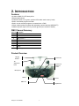
2. INTRODUCTION
Features
• 8-channel DMX-512 LED derby effect
• Blackout/static/strobe
• Individual control of red, green, and blue LEDs within each cluster (6 total)
• Built-in automated programs via DMX
• Built-in sound activated programs via master/slave or DMX
• Mount multiple products together with adjustable, optional bracket (XBRACKET)
• Additional power output: max 27 products @ 120V (see manual for details)
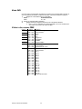
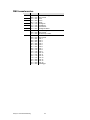
DMX Channel Summary
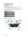
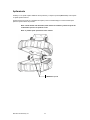
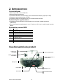
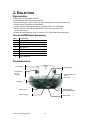
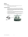
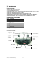
Product Overview
Channel
Description
1
LED Cluster 1
2
LED Cluster 2
3
LED Cluster 3
4
LED Cluster 4
5
LED Cluster 5
6
LED Cluster 6
7
Strobe
8
Auto Programs
Power Link Out
Dipswitches
DMX In
Power In &
External
Fuse
Power Out
Tilt
Adjustment
Knob
Sound
DMX Out
Microphone
Hanging
Bracket

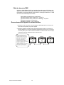
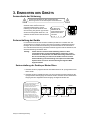
Derby X™ User Manual 8
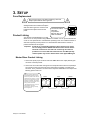
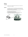
Often, the setup for Master-Slave
and Standalone operation requires
that the first product in the chain be
initialized for this purpose via either
settings in the control panel or DIP-
switches. Secondarily, the products
that follow may also require a slave
setting. Please consult the
“Operating Instructions” section in
this manual for complete
instructions for this type of setup
and configuration.
Master
Slave
Slave
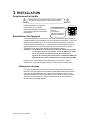
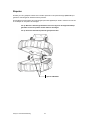
The fuse is located
inside this
compartment.
Remove using a flat
head screwdriver.
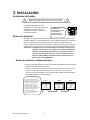
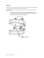
3. SETUP
Fuse Replacement
With a flat-head screwdriver wedge the fuse holder out of its housing. Remove the
damaged fuse from its holder and replace
with exact same type fuse. Insert the fuse
holder back in its place and reconnect
power.
Product Linking
You will need a serial data link to run light
shows of one or more products using a DMX-512 controller or to run synchronized shows
on two or more products set to a master/slave operating mode. The combined number of
channels required by all the products on a serial data link determines the number of
products the data link can support.
Important: Products on a serial data link must be daisy chained in one single
line. To comply with the EIA-485 standard no more than 32 devices
should be connected on one data link. Connecting more than 32
products on one serial data link without the use of a DMX optically-
isolated splitter may result in deterioration of the digital DMX signal.
Master/Slave Product Linking
1. Connect the (male) 3 pin connector side of the DMX cable to the output (female) 3 pin
connector of the first product.
2. Connect the end of the cable coming from the first product which will have a (female) 3
pin connector to the input connector of the next product consisting of a (male) 3 pin
connector. Then, proceed to connect from the output as stated above to the input of the
following product and so on.
Disconnect the power cord before replacing a fuse and
always replace with the same type fuse.

Derby X™ User Manual 9
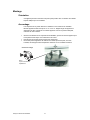
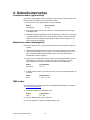
Hanging Clamp
Note!
Clamp is sold separately.
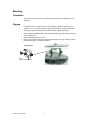
Mounting
Orientation
This product may be mounted in any safe position provided there is adequate room for
ventilation.
Rigging
It is important never to obstruct the fan or vents pathway. Mount the product using, a
suitable “C” or “O” type clamp. Adjust the angle of the product by loosening both knobs
and tilting the product. After finding the desired position, retighten both knobs.
• When selecting installation location, take into consideration lamp replacement access and
routine maintenance.
• Safety cables must always be used.
• Never mount in places where the product will be exposed to rain, high humidity, extreme
temperature changes or restricted ventilation.

Derby X™ User Manual 10
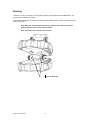
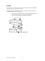
Stacking
The Derby X™ may be “stacked” by using multiple products and the optional bracket (XBRACKET). This
bracket may be ordered from Chauvet.
The bracket kit will ship with 2pcs bracket (as shown below) and will include 4 screws for attaching it to the
bottom of the product.
Note: When you are installing this bracket, you must use the washers and bracket
tightening knob to secure one product to another.
Note: A maximum of 4 products can be stacked.
Optional XBRACKET

Derby X™ User Manual 11
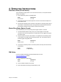
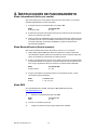
4. OPERATING INSTRUCTIONS
Standalone Mode (Sound-Active):
This mode allows a single product to run to the beat of the music, or the product will auto
change in Auto Mode.
1) Set all dipswitches position to the Off position.
Mode Dipswitches
Sound Active 10 = Off
2) The product will react to the low frequencies of music via the internal microphone in
Sound-Active mode.
3) Use the audio sensitivity knob on the back of the product to make the product more or
less sensitive in Sound-Active mode. Turning the knob counterclockwise decreases
the sensitivity; turning the knob clockwise increases the sensitivity.
Master/Slave Mode (Master Sound):
This mode will allow you to link up to 32 products together without a controller.
1) Use standard DMX cables to daisy chain your products together via the DMX
connector on the rear of the products. For longer cable runs we suggest a terminator
at the last product.
2) Choose a product to function as the Master. Turn dipswitches to the Master position
on the product. The product must be the first product in line. Then simply chain the
products together using DMX cable.
Mode Dipswitches
Master Sound 10 = Off
3) Turn switch to the Slave position on the slave products, and they will react the same
as the Master.
Mode Dipswitches
Slave 1 = On, 10 = On
DMX Mode
If you are unfamiliar with DMX, download the DMX Primer from the
www.chauvetlighting.com website.
1) Set the dipswitches to DMX mode.
Mode Dipswitches
DMX 10 = On
2) Connect a DMX controller to the product.
3) Set the start address according to standard binary code.

Derby X™ User Manual 12
DMX Channel Values
Channel
Value
Function
1
000 010
011 045
046 080
081 115
116 150
151 185
186 220
221 255
Cluster Control
No function
Red
Green
Blue
Red/Green
Red/Blue
Green/Blue
Red/Green/Blue
2
3
4
5
6
7
000 010
011
255
Strobe
No function
Strobe 0%~100%
8
000 010
011 024
025 038
039 052
053 066
067 080
081 094
095 108
109 122
123 136
137 150
151 164
165 178
179 192
193 206
207 220
221 250
251 255
Auto Speed
No function
Auto 1
Auto 2
Auto 3
Auto 4
Auto 5
Auto 6
Auto 7
Auto 8
Auto 9
Auto 10
Auto 11
Auto 12
Auto 13
Auto 14
Auto 15
Auto 16
Audio trigger

Derby X™ User Manual 13
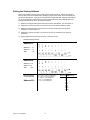
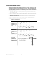
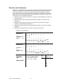
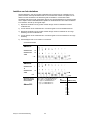
Setting the Starting Address
Set the start address using the group of DIP switches located usually on bottom of the product.
Each dip switch has an associated value. Adding the value of each switch in the ON position will
provide the start address. Figuring out which switches to toggle ON given a specific start address
can be accomplished by determining which switch values will add up to the address value and
turning these switches on. Do so by doing the following:
1) Determine the largest value switch that is less than the start address. Turn this switch on.
2) Subtract the value of the switch you just turned on from the starting address number.
3) Determine the largest value switch that is less than the remainder from the previous
subtraction. Turn this switch on.
4) Subtract the value of the switch you just turned on from the remainder of the previous
subtraction.
5) Repeat steps three and four until you have a remainder of zero.
Example Starting Address
Address 10
Switch # 4 = 8
Switch # 2 = 2
Total = 10
Address 24
Switch # 5 = 16
Switch # 4 = 8
Total = 24
Resolving address
using simple math.
Address 233
233 – (128) = 105, Turn ON Dip # 8
105 – (64) = 41, Turn ON Dip # 7
41 – (32) = 9, Turn ON Dip # 6
9 – (8) = 1, Turn ON Dip # 4
1 – (1) = 0, Turn ON Dip # 1
DIPSWITCH
(DMX VALUE)
1
2
3
4
5
6
7
8
9
1
2
4
8
16
32
64
128
256

Derby X™ User Manual 14
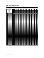
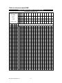
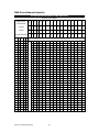
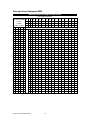
DMX Quick Reference Chart
DMX Address Quick Reference Chart
Dip Switch Position
DMX DIP
SWITCH SET
#9
0 0 0 0 0 0 0 0 1 1 1 1 1 1 1 1
0=OFF
#8
0
0
0
0
1
1
1
1
0
0
0
0
1
1
1
1
1=ON
#7
0
0
1
1
0
0
1
1
0
0
1
1
0
0
1
1
X=OFF or ON
#6
0
1
0
1
0
1
0
1
0
1
0
1
0
1
0
1
#1
#2
#3
#4
#5
0
0
0
0
0
32
64
96
128
160
192
224
256
288
320
352
384
416
448
480
1
0
0
0
0
1
33
65
97
129
161
193
225
257
289
321
353
385
417
449
481
0
1
0
0
0
2
34
66
98
130
162
194
226
258
290
322
354
386
418
450
482
1
1
0
0
0
3
35
67
99
131
163
195
227
259
291
323
355
387
419
451
483
0
0
1
0
0
4
36
68
100
132
164
196
228
260
292
324
356
388
420
452
484
1
0
1
0
0
5
37
69
101
133
165
197
229
261
293
325
357
389
421
453
485
0
1
1
0
0
6
38
70
102
134
166
198
230
262
294
326
358
390
422
454
486
1
1
1
0
0
7
39
71
103
135
167
199
231
263
295
327
359
391
423
455
487
0
0
0
1
0
8
40
72
104
136
168
200
232
264
296
328
360
392
424
456
488
1
0
0
1
0
9
41
73
105
137
169
201
233
265
297
329
361
393
425
457
489
0
1
0
1
0
10
42
74
106
138
170
202
234
266
298
330
362
394
426
458
490
1
1
0
1
0
11
43
75
107
139
171
203
235
267
299
331
363
395
427
459
491
0
0
1
1
0
12
44
76
108
140
172
204
236
268
300
332
364
396
428
460
492
1
0
1
1
0
13
45
77
109
141
173
205
237
269
301
333
365
397
429
461
493
0
1
1
1
0
14
46
78
110
142
174
206
238
270
302
334
366
398
430
462
494
1
1
1
1
0
15
47
79
111
143
175
207
239
271
303
335
367
399
431
463
495
0
0
0
0
1
16
48
80
112
144
176
208
240
272
304
336
368
400
432
464
496
1
0
0
0
1
17
49
81
113
145
177
209
241
273
305
337
369
401
433
465
497
0
1
0
0
1
18
50
82
114
146
178
210
242
274
306
338
370
402
434
466
498
1
1
0
0
1
19
51
83
115
147
179
211
243
275
307
339
371
403
435
467
499
0
0
1
0
1
20
52
84
116
148
180
212
244
276
308
340
372
404
436
468
500
1
0
1
0
1
21
53
85
117
149
181
213
245
277
309
341
373
405
437
469
501
0
1
1
0
1
22
54
86
118
150
182
214
246
278
310
342
374
406
438
470
502
1
1
1
0
1
23
55
87
119
151
183
215
247
279
311
343
375
407
439
471
503
0
0
0
1
1
24
56
88
120
152
184
216
248
280
312
344
376
408
440
472
504
1
0
0
1
1
25
57
89
121
153
185
217
249
281
313
345
377
409
441
473
505
0
1
0
1
1
26
58
90
122
154
186
218
250
282
314
346
378
410
442
474
506
1
1
0
1
1
27
59
91
123
155
187
219
251
283
315
347
379
411
443
475
507
0
0
1
1
1
28
60
92
124
156
188
220
252
284
316
348
380
412
444
476
508
1
0
1
1
1
29
61
93
125
157
189
221
253
285
317
349
381
413
445
477
509
0
1
1
1
1
30
62
94
126
158
190
222
254
286
318
350
382
414
446
478
510
1
1
1
1
1
31
63
95
127
159
191
223
255
287
319
351
383
415
447
479
511
Dip Switch Position DMX Address

Derby X™ User Manual 15
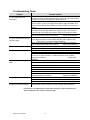
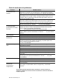
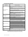
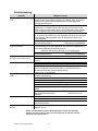
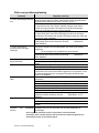
Troubleshooting Guide
Problem Possible Solution
1 or more LED’s are not
illuminating
Clean the product regularly to avoid any such failure. This product is
convection cooled, which means that if the surface is kept clean and free
of debris, then proper cooling will be allowed to occur
An LED may have failed, resulting in an open circuit. In this event, all of
the red, green, or blue in a single module will no longer illuminate. This
does not mean that all of the LEDs have failed, but the circuit is wired in
series.
An LED may have failed, resulting in a short circuit. In this event, only
the single LED which has failed will no longer function. This does not
mean that all of the LEDs have failed, but the circuit is wired in series.
Note: In the event of LED failure, a replacement LED PCB assembly
may be purchased directly from Chauvet Part#: P222-DERBYX
1 or more LED’s are producing
very low output
Check that the lens assembly is installed properly. If the lens assembly
is not aligned properly over the LEDs, then they will not project fully
-See section on Lens Assembly Installation
Note: In the event of LED failure, a replacement LED PCB assembly
may be purchased directly from Chauvet Part#: P222-DERBYX
Breaker/Fuse keeps blowing
Check total load placed on the electrical circuit
Check for a short in the electrical wiring: internal and/or external
Device has no power
Check device’s fuse (internal)
Check for power on Mains
Note: In the event of auto-switching transformer failure, the product can
be sent in for repair; however, a replacement part can be ordered
directly from Chauvet Part#: P140-
DERBYX
Product is not responding to
DMX
Check Control Panel settings for correct addressing
Check DMX cables
Check polarity switch settings on the controller
Check cable connections
Call service technician
See page #10 for proper settings to operate in DMX mode
Note: In the event of Master PCB failure, a replacement PCB can be
ordered directly from Chauvet Part#: P172-DERBYX
Loss of signal
Use only DMX cables
Install terminator
Note: Keep DMX cables separated from power cables or black lights
Standalone operation problem See page #8 & #10 for details on proper settings and connections
If you still have a problem after trying the above solutions, please contact Chauvet
Technical Support at the location on the next page.

Derby X™ User Manual 16
5. APPENDIX
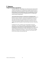
General Maintenance
To maintain optimum performance and minimize wear products should be cleaned
frequently. Usage and environment are contributing factors in determining frequency. As a
general rule, products should be cleaned at least twice a month. Dust build up reduces
light output performance and can cause overheating. This can lead to reduced lamp life
and increased mechanical wear. Be sure to power off product before conducting
maintenance.
Unplug product from power. Use a vacuum or air compressor and a soft brush to remove
dust collected on external vents and internal components. Clean all glass when the
product is cold with a mild solution of glass cleaner or Isopropyl Alcohol and a soft lint free
cotton cloth or lens tissue. Apply solution to the cloth or tissue and drag dirt and grime to
the outside of the lens. Gently polish optical surfaces until they are free of haze and lint.
The cleaning of internal and external optical lenses and/or mirrors must be carried out
periodically to optimize light output. Cleaning frequency depends on the environment in
which the product operates: damp, smoky or particularly dirty surrounding can cause
greater accumulation of dirt on the product’s optics. Clean with soft cloth using normal
glass cleaning fluid. - Always dry the parts carefully. - Clean the external optics at least
every 20 days. Clean the internal optics at least every 30/60 days.
Returns Procedure
Returned merchandise must be sent prepaid and in the original packing, call tags will not
be issued. Package must be clearly labeled with a Return Merchandise Authorization
Number (RMA #). Products returned without an RMA # will be refused. Call Chauvet and
request RMA # prior to shipping the product. Be prepared to provide the model number,
serial number and a brief description of the cause for the return. Be sure to properly pack
product, any shipping damage resulting from inadequate packaging is the customer’s
responsibility. Chauvet reserves the right to use its own discretion to repair or replace
product(s). As a suggestion, proper FedEx packing or double-boxing are recommended.
Note: If you are given an RMA #, please include the following information on a
piece of paper inside the box:
1) Your name
2) Your address
3) Your phone number
4) The RMA #
5) A brief description of the symptoms
Claims
Damage incurred in shipping is the responsibility of the shipper; therefore the damage
must be reported to the carrier upon receipt of merchandise. It is the customer's
responsibility to notify and submit claims with the shipper in the event that a product is
damaged due to shipping. Any other claim for items such as missing component/part,
damage not related to shipping, and concealed damage, must be made within seven (7)
days of receiving merchandise.

Derby X™ User Manual 17
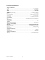
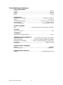
Technical Specifications
WEIGHT & DIMENSIONS
Length ................................................................................................................................... 11.9 in (302 mm)
Width ........................................................................................................................................ 15 in (382 mm)
Height ...................................................................................................................................... 7.4 in (187 mm)
Weight ........................................................................................................................................... 4 lb (1.8 kg)
POWER
Auto-switching power supply ....................................................................................... 100-240V AC 50/60 Hz
Fuse ............................................................................................................................................. F 1 A, 250 V
Power Consumption ............................................................................................... 24 W (0.2 A) max at 120 V
Inrush Power ........................................................................................................................... (0.2 A) at 120 V
Power Output .......................................................................................................... 27 products max at 120 V
LIGHT SOURCE
LED ............................................................................................... 90 (30 red, 30 green, 30 blue) 100,000 hrs
PHOTO OPTIC
Coverage Angle ......................................................................................................................................... 96°
THERMAL
Maximum ambient temperature ................................................................................................. 104 °F (40 °C)
CONTROL & PROGRAMMING
Data input ......................................................................................................... locking 3-pin XLR male socket
Data output.................................................................................................... locking 3-pin XLR female socket
Data pin configuration ...................................................................................... pin 1 shield, pin 2 (-), pin 3 (+)
Protocols ............................................................................................................................... DMX-512 USITT
DMX Channels ............................................................................................................................................... 8
ORDERING INFORMATION
Derby X™.......................................................................................................................................... DERBYX
Optional bracket ........................................................................................................................... XBRACKET
WARRANTY INFORMATION
Warranty....................................................................................................................... 2-year limited warranty

Manual de Usuario Derby X™ 18
1. ANTES DE EMPEZAR
Qué va incluido
1 x Derby X™
Cable de alimentación
Tarjeta de garantía
Manual de usuario
Instrucciones de desembalaje
Inmediatamente después de recibir un producto, desembale con cuidado la caja,
compruebe el contenido para asegurarse de que están presentes todas las piezas y de
que se han recibido en buen estado. Si cualquier elemento parece dañado a causa del
transporte o la propia caja muestra signos de manipulación inadecuada, notifíquelo
inmediatamente al expedidor y quédese con el material de embalaje para su inspección.
Guarde la caja y todos los materiales de embalaje. En caso de que el producto tenga que
devolverse a la fábrica, es importante que la devolución del producto se realice en la
misma caja y embalaje originales de fábrica.
Corriente alterna
Este producto tiene una fuente de alimentación con conmutación automática. Este
dispositivo se adaptará entre 100 VCA y 240 VCA, 50/60 Hz. Todos los productos deben
funcionar directamente dentro de un circuito conmutado, y no deben ser utilizados en un
circuito con reostato (resistor variable) o atenuador (dimmer), incluso si el canal del
reostato o atenuador sirve solo como conmutador 0 a 100%.

Manual de Usuario Derby X™ 19
Notas de seguridad
• Guarde este Manual de usuario para futuras consultas. Si vende este producto a otro
usuario, asegúrese de que este recibe también este libreto de instrucciones.
• Asegúrese siempre de que conecta el producto a la tensión adecuada, y de que la tensión
de la línea a la que está conectándolo no es superior a la establecida en la impresión o en
el panel posterior del producto.
• ¡Este producto está destinado al uso en interiores solamente! Para evitar riesgos de
incendio o descarga, no exponga el producto a la lluvia o la humedad. Asegúrese de que
no hay materiales inflamables cerca del producto cuando esté en funcionamiento.
• El producto debe instalarse en una ubicación con ventilación adecuada, al menos a 20 in
(50 cm) de superficies adyacentes. Asegúrese de que no se han bloqueado las ranuras
de ventilación.
• Desconecte siempre de la fuente de alimentación antes de repararlo o sustituir la lámpara
o el fusible, y asegúrese de sustituir el fusible con una lámpara de la misma clase.
• Sujete el producto a un dispositivo de fijación usando una cadena de seguridad.
• Nunca transporte el producto sujetándolo solo por la cabeza. Utilice las asas de
transporte.
• La temperatura ambiente (Ta) máxima es de 40 °C (104 °F). No haga funcionar el
producto a temperaturas más altas que esta.
• En caso de un problema grave de funcionamiento, deje de usar el producto
inmediatamente. Nunca intente reparar el producto usted mismo. Las reparaciones
llevadas a cabo por personal no cualificado pueden provocar averías o funcionamiento
defectuoso. Póngase en contacto con el centro de asistencia técnica autorizado más
cercano. Utilice siempre el mismo tipo de piezas de repuesto.
• Nunca conecte el dispositivo a un regulador de intensidad o reostato.
• Asegúrese de que el cable de alimentación no está retorcido ni estropeado.
• Nunca desconecte el cable de alimentación agarrando o tirando del cable.
• Evite la exposición directa de los ojos a la fuente de luz mientras esté encendido.
• Para evitar el desgaste y alargar su vida útil, desconecte completamente el producto
mediante el interruptor o desenchufándolo durante periodos en que no se use.
¡Cuidado! No hay piezas reparables por el usuario dentro del producto. No
abra la carcasa ni intente ninguna reparación por sí mismo. En el
caso improbable de que su unidad requiera reparación, póngase en
contacto con el Servicio técnico de Chauvet.
Por favor, lea estas instrucciones detenidamente, ya que
incluyen información importante sobre la instalación, uso y
mantenimiento de este producto.

Manual de Usuario Derby X™ 20
2. INTRODUCCIÓN
Características
• Efecto derby LED DMX-512 de 8 canales
• Blackout/estático/estroboscopio
• Control individual de los LED rojos, verdes y azules dentro de cada grupo (6 en total)
• Programas automáticos incorporados a través de DMX
• Programas activados por sonido integrados a través de maestro/esclavo o DMX
• Monte varios productos juntos con el soporte ajustable opcional (XBRACKET)
• Salida de alimentación adicional: máx. 27 productos a 120 V (vea el manual para detalles)
Resumen de canales DMX
Visión general del producto
Canal
Descripción
1
Grupo LED 1
2
Grupo LED 2
3
Grupo LED 3
4
Grupo LED 4
5
Grupo LED 5
6
Grupo LED 6
7
Estroboscopio
8
Programas automáticos
Salida de
Interruptores DIP
Entrada
DMX
Entrada de
alimentación y
externa
Fusible
Salida de
alimentación
Mando de
ajuste de
inclinación
Ajuste de sonido
Salida DMX
Micrófono
Soporte para
colgar
La page est en cours de chargement...
La page est en cours de chargement...
La page est en cours de chargement...
La page est en cours de chargement...
La page est en cours de chargement...
La page est en cours de chargement...
La page est en cours de chargement...
La page est en cours de chargement...
La page est en cours de chargement...
La page est en cours de chargement...
La page est en cours de chargement...
La page est en cours de chargement...
La page est en cours de chargement...
La page est en cours de chargement...
La page est en cours de chargement...
La page est en cours de chargement...
La page est en cours de chargement...
La page est en cours de chargement...
La page est en cours de chargement...
La page est en cours de chargement...
La page est en cours de chargement...
La page est en cours de chargement...
La page est en cours de chargement...
La page est en cours de chargement...
La page est en cours de chargement...
La page est en cours de chargement...
La page est en cours de chargement...
La page est en cours de chargement...
La page est en cours de chargement...
La page est en cours de chargement...
La page est en cours de chargement...
La page est en cours de chargement...
La page est en cours de chargement...
La page est en cours de chargement...
La page est en cours de chargement...
La page est en cours de chargement...
La page est en cours de chargement...
La page est en cours de chargement...
La page est en cours de chargement...
La page est en cours de chargement...
La page est en cours de chargement...
La page est en cours de chargement...
La page est en cours de chargement...
La page est en cours de chargement...
La page est en cours de chargement...
La page est en cours de chargement...
La page est en cours de chargement...
La page est en cours de chargement...
La page est en cours de chargement...
La page est en cours de chargement...
La page est en cours de chargement...
La page est en cours de chargement...
-
 1
1
-
 2
2
-
 3
3
-
 4
4
-
 5
5
-
 6
6
-
 7
7
-
 8
8
-
 9
9
-
 10
10
-
 11
11
-
 12
12
-
 13
13
-
 14
14
-
 15
15
-
 16
16
-
 17
17
-
 18
18
-
 19
19
-
 20
20
-
 21
21
-
 22
22
-
 23
23
-
 24
24
-
 25
25
-
 26
26
-
 27
27
-
 28
28
-
 29
29
-
 30
30
-
 31
31
-
 32
32
-
 33
33
-
 34
34
-
 35
35
-
 36
36
-
 37
37
-
 38
38
-
 39
39
-
 40
40
-
 41
41
-
 42
42
-
 43
43
-
 44
44
-
 45
45
-
 46
46
-
 47
47
-
 48
48
-
 49
49
-
 50
50
-
 51
51
-
 52
52
-
 53
53
-
 54
54
-
 55
55
-
 56
56
-
 57
57
-
 58
58
-
 59
59
-
 60
60
-
 61
61
-
 62
62
-
 63
63
-
 64
64
-
 65
65
-
 66
66
-
 67
67
-
 68
68
-
 69
69
-
 70
70
-
 71
71
-
 72
72


CHAUVET DJ Derby X Manuel utilisateur
- Catégorie
- Stroboscopes
- Taper
- Manuel utilisateur
dans d''autres langues
- español: CHAUVET DJ Derby X Manual de usuario
- Deutsch: CHAUVET DJ Derby X Benutzerhandbuch
- Nederlands: CHAUVET DJ Derby X Handleiding
Documents connexes
-
CHAUVET DJ Derby X Guide de référence
-
-
-
-
-
-
-
