
1
REV 1 - 1904251330
L-A2-413
Robert H. Peterson Co. • 14724 East Proctor Avenue • City of Industry, CA 91746
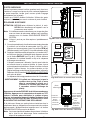
IMPORTANT: READ THESE INSTRUCTIONS
CAREFULLY BEFORE STARTING
INSTALLATION OR USE.
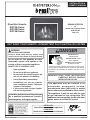
INSTALLATION &
OWNER’S MANUAL
Do not store or use gasoline or other
flammable vapors and liquids in the
vicinity of this or any other appliance.
WHAT TO DO IF YOU SMELL GAS:
• Open a window.
• Do not try to light any appliance.
• Do not touch any electrical switch; do
not use any phone in the building.
• Leave the building immediately.
• Immediately call the gas supplier
from a neighbor’s phone. Follow gas
supplier’s instructions.
• If you cannot reach the gas supplier,
call the fi re department.
Installation and service must be performed
by a qualified professional installer,
service agency, or the gas supplier.
DESIGN CERTIFIED
to
Vented Gas Fireplace Heater
ANSI Z21.88
CSA 2.33
INSTALLER:
Leave this manual with the appliance.
CONSUMER:
Retain this manual for future reference.
This appliance may be installed in an
aftermarket, permanently located,
manufactured home (USA only) or mobile
home, where not prohibited by local codes.
This appliance is only for use with the type
of gas indicated on the rating plate. This
appliance is not convertible for use with other
gases, unless a certifi ed kit is used.
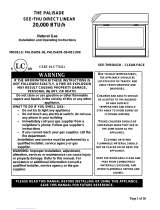
WARNING:
FIRE OR EXPLOSION HAZARD
Failure to follow safety warnings exactly could
result in serious injury, death, or property damage.
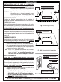
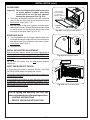
DANGER
A barrier designed to reduce the risk of burns from the hot
viewing glass is provided with this appliance and shall be
installed for the protection of children and other at-risk
individuals.
HOT GLASS WILL
CAUSE BURNS.
DO NOT TOUCH GLASS
UNTIL COOLED.
NEVER ALLOW CHILDERN
TO TOUCH GLASS.
US
®
C
Direct Vent Inserts:
DVIT-25i Series
DVIT-30i Series
DVIT-36i Series
DVIT DIRECT VENT INSERTS - INTERMITTENT PILOT IGNITION (IPI) SYSTEM

2
REV 1 - 1904251330
L-A2-413
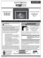
INSTALLATEUR :
Laissez ce manuel avec l'appareil.
CONSOMMATEUR:
Maintenez ce manuel pour la future référence.
Robert H. Peterson Co. • 14724 East Proctor Avenue • City of Industry, CA 91746
IMPORTANT: LISEZ CES INSTRUCTIONS
SOIGNEUSEMENT AVANT DE
COMMENCER L'INSTALLATION OU
L'UTILISATION.
Ne stockez pas ou n’employez pas l’essence
ou d’autres vapeurs et liquides infl ammables
à proximité de ceci ou d’aucun autre appareil.
CE QUI À FAIRE SI VOUS SENTEZ LE GAZ:
• Ouvrez une fenêtre.
• N’essayez pas de n’allumer aucun appareil.
• Ne touchez aucun commutateur
électrique; n’utilisez aucun téléphone
dans le bâtiment.
• Quitter immédiatement le bâtiment.
• Appelez immédiatement le fournisseur
de gaz du téléphone du voisin. Suivez
les instructions du fournisseur de gaz.
• Si vous ne pouvez pas atteindre
le fournisseur de gaz, appelez le
département de feu.
L’installation et le service doivent être assurés
par un installateur qualifi é et professionnel,
l’agence de service, ou le fournisseur de gaz.
Cet appareil peut être installé dans un marché des
accessoires, une maison de manière permanente
située et manufacturée (Etats-Unis seulement)
ou une caravane résidentielle, où non interdit par
des codes locaux.
Cet appareil sert seulement avec le type de gaz
indiqué de la plaque de contrôle. Cet appareil
n'est pas convertible pour l'usage avec d'autres
gaz, à moins qu'un kit certifi é soit employé.
CONCEPTION CERTIFIÉE
à
Réchauffeur exhalé
de cheminée de gaz
ANSI Z21.88
CSA 2.33
INSTALLATION ET
MODE D'EMPLOI
DANGER
Une barrière conçu pour réduire le risque de brûlures par
le verre de visualisation chaude est fournie avec cet
appareil et doit être installé pour la protection des enfants
et autres personnes à risque.
UNA SURFACE VITRÉE CHAUDE
PEUT CAUSER DES BRÛLURES.
LAISSER REFROIDIR LA SURFACE
VITRÉE AVANT D'Y TOUCHER.
NE PERMETTEZ JAMAIS À UN
ENFANT DE TOUCHER LA
SURFACE VITRÉE.
ATTENTION:
INCENDIE OU EXPLOSION
Le non-respect des avertissements de sécurité
serait exactement entraîner des blessures graves,
la mort ou des dommages matériels.
US
®
C
Direct Vent Inserts:
DVIT-25i Série
DVIT-30i Série
DVIT-36i Série
DVIT INSERTS D'ÉVACUATION DIRECTE - SYSTÈME D'ALLUMAGE PILOTE INTERMITTENT (IPI)

3
REV 1 - 1904251330
L-A2-413
TABLE OF CONTENTS
GETTING STARTED
IMPORTANT PRE-INSTALLATION AND SAFETY
INFORMATION ..............................................................5
NOTES PAGE .................................................................6
LISTING AND CODE APPROVALS .............................7
LISTING ...................................................................7
CODE REQUIREMENTS ...........................................7
COMMONWEALTH OF MASSACHUSETTS REQUIRE-
MENTS
..................................................................... 7
SPECIFICATIONS AND DIMENSIONS .......................8
MINIMUM CLEARANCES .........................................13
TOOLS REQUIRED .....................................................13
REPLACEMENT PARTS LIST ....................................14
INSTALLATION REQUIREMENTS ...........................20
FIREPLACE REQUIREMENTS ................................20
GAS PRESSURE REQUIREMENTS ..........................21
VENTING REQUIREMENTS ....................................21
INSTALLATION
INSTALLATION ...........................................................23
BEFORE YOU BEGIN .............................................23
GAS SUPPLY SETUP ..............................................23
ELECTRICAL SETUP ..............................................23
VENTING ...............................................................24
DIRECT VENT INSERT ...........................................26
INSTALL BATTERIES ..............................................28
INSTALL WALL MOUNT REMOTE HOLDER ............ 28
FIRST TIME PILOT LIGHTING TEST ......................29
FIRST TIME BURNER LIGHTING TEST ...................30
GAS PRESSURE TEST .............................................30
FIREBOX LINERS ...................................................31
LOG SET AND EMBER PLACEMENT ......................33
SURROUND FASCIA ...............................................34
FASTEN RETENTION BRACKET (if applicable) ........34
SECURE UNIT TO FLOOR ......................................34
GLASS PANEL.........................................................35
SURROUND DOOR ................................................35
INITIAL AIR SHUTTER ADJUSTMENT ....................35
FIRST TIME BURN-OFF PERIOD ...........................35
NOTES PAGE ...............................................................36
USE, CARE, & SERVICE
LIGHTING INSTRUCTIONS ......................................37
FOR YOUR SAFETY READ BEFORE LIGHTING ...... 37
AUTOMATIC PILOT THERMAL SWITCH .................37
EXTENDED USE ....................................................37
SURROUND DOOR ................................................39
REMOTE LIGHTING ............................................... 39
MANUAL LIGHTING...............................................41
SHUTTING DOWN .................................................. 41
FAN OPERATION DURING MANUAL USE .............41
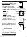
REMOTE OPERATION INSTRUCTIONS ..................43
ORIENTATION ........................................................ 43
FLAME HEIGHT
....................................................43
FAN
.......................................................................43
ACCENT LIGHT
..................................................... 45
REMOTE MODE AND THERMOSTAT MODE ..........45
TIMER .................................................................... 45
STANDING PILOT MODE .......................................47
TEMPERATURE INDICATOR ( ˚F or ˚C) .................. 47
KEY LOCK
.............................................................47
OPERATING DURING A POWER OUTAGE .............47
SERVICING AND CLEANING ...................................49
ANNUAL CLEAN / INSPECTION .............................49
GLASS PANEL REMOVAL AND MAINTENANCE ......50
PILOT BURNER APPEARANCE ..............................50
AIR SHUTTER ADJUSTMENT .................................51
BATTERY REPLACEMENT ......................................53
SYNCHRONIZE REMOTE SYSTEM .......................... 54
FAN ASSEMBLY CLEANING .................................... 55
FUEL CONVERSION KITS ......................................55
NOTES PAGE ...............................................................56
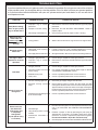
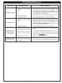
TROUBLESHOOTING ................................................57
WARRANTY .................................................................60
IMPORTANT SAFETY INFORMATION
Congratulations on your purchase of an R. H. Peterson Co. Real Fyre direct vent insert. Made with pride in
America, your new insert complies with national safety standards and when installed per these instructions and
used as intended it will provide warmth and comfort to your home for many years.
Due to the extreme heat output of the insert, there is a risk of burns if care is not taken in the operation of
the unit. PLEASE READ THE SAFETY AND OPERATION INFORMATION AND WARNINGS IN THIS MANUAL
BEFORE USING YOUR INSERT. Be aware that glass panels and other surfaces get extremely HOT and can
cause burns if touched. Factory-provided barrier screens help to reduce the risk of serious burns as they can
prevent direct contact with the glass. However, barrier screens still retain heat and must not be touched. The
insert glass and surrounding material will remain HOT for a period of time after the unit is turned off, so caution
should be used at all times.
Refer to all safety information and warnings provided in this manual.

4
L'INFORMATION IMPORTANTE DE PRÉINSTALLATION ET DE SÛRETÉ
AVERTISSEMENT!
A. Lisez toutes les instructions. Ne pas installer ou d'utiliser cet appareil sans avoir lu et compris ce manuel. Ne pas
suivre les instructions de ce manuel se traduira par un appareil mal installé et opérationnel, annuler la garantie,
et peut être dangereux.
B. Une mauvaise installation, le réglage, la modifi cation, le service, la maintenance, ou de l'utilisation peuvent causer
des blessures graves, la mort ou des dommages matériels. Reportez-vous à ce manuel. Pour de l'aide ou des
informations supplémentaires, consultez un technicien professionnel qualifi é de service, un organisme de service
ou le fournisseur de gaz.Instructions à la terre électrique - Cet appareil est équipé d'un à trois broches (mise à la
terre) pour vous protéger contre les chocs électriques et doit être branchée directement dans une prise à trois
broches prise. Ne pas couper ou enlever la broche de terre de cette fi che.
C. Dispositions pour la combustion adéquate et l'air de ventilation doit être maintenue.
Voir la EXIGENCES DE
VENTILATION section pour plus de détails.
D. Instructions à la terre électrique - Cet appareil est équipé d'un à trois broches (mise à la terre) pour vous protéger
contre les chocs électriques et doit être branchée directement dans une prise à trois broches prise. Ne pas couper
ou enlever la broche de terre de cette fi che.
E. Ne pas placer les pièces conformément à ce manuel ou de l'échec d'utiliser seulement les pièces approuvées pour
cet appareil peut entraîner des dommages matériels ou des blessures corporelles.
F. Installation, maintenance et de réparation doit être effectuée par un technicien de service professionnel qualifi é.
G. Un inspecteur en bâtiment local devriez revoir vos plans avant l'installation.
H. Soyez extrêmement prudent lors de la manipulation de ce produit et ses accessoires car ils ont des bords tranchants
qui peuvent causer des blessures.
I. Il est recommandé que les détecteurs de fumée sont installés dans la maison. Si possible, installez un détecteur
dans un couloir adjacent à la salle (pour éviter une fausse alarme de la chaleur de l'appareil). Cependant, vous
devez suivre les exigences du code local.
J. Toute modifi cation ou altération peut annuler la garantie, la certifi cation et les annonces de cet appareil.
K. Dégagements d'accessibilité adéquats pour l'entretien et doit être prévu.
L. Un dégagement suffi sant autour des ouvertures d'air dans la chambre de combustion doit être maintenue.
M. Cet appareil au gaz ne doit pas être raccordé à un conduit de cheminée desservant un autre appareil de combustion
séparée à combustible solide.
N. Ne pas utiliser cet appareil si une pièce a été sous l'eau. Appelez immédiatement un technicien de service qualifi é
pour inspecter l'appareil et pour remplacer toute pièce du système de contrôle et de contrôle du gaz qui a été sous
l'eau.
O. En raison des températures élevées, l'appareil doit être placé hors de la circulation et loin des meubles et des rideaux.
P. Hot en cours de fonctionnement. Enfants et adultes doivent être avertis des dangers de la température de surface
élevée et devrait rester à l'écart pour éviter les brûlures ou l'infl ammation des vêtements.
Q. Les jeunes enfants doivent être surveillés quand ils sont dans la même pièce que l'appareil. Tout-petits, les
jeunes enfants et d'autres peuvent être sensibles à des brûlures de contact accidentel. Une barrière physique est
recommandé s'il ya des individus à risque dans la maison. Pour restreindre l'accès à une cheminée ou un poêle,
installer une barrière de sécurité pour garder les tout-petits, les jeunes enfants et d'autres personnes à risque hors
de la salle et à l'écart des surfaces chaudes.
R. Les vêtements ou autres matériaux infl ammables ne doivent pas être placés sur ou près de l'appareil. Ne placez
jamais les combustibles solides, liquides infl ammables, ou des objets étrangers dans cet appareil.
S. Tout écran ou grille de protection pour l'entretien d'un appareil doit être remplacé avant de faire fonctionner l'appareil.
T. Installation et réparation doit être effectuée par un technicien qualifi é. L'appareil doit être inspecté avant son
utilisation et au moins annuellement par une personne un service professionnel. Un nettoyage plus fréquent peut
être nécessaire en raison des peluches provenant des tapis, literie, etc. Il est impératif que les compartiments de
contrôle, les brûleurs et les passages de circulation d'air de l'appareil être maintenu propre.
U. Seulement trousse de garniture (s) fournie par le fabricant doivent être utilisées dans l'installation de cet appareil.
Ouvertures de secours projets ne doivent pas être couverts ou bloqués. Panneaux de garniture ou entoure ne doit
pas sceller les ouvertures de ventilation dans la cheminée.
CONSERVER CES INSTRUCTIONS

5
IMPORTANT PRE-INSTALLATION AND SAFETY INFORMATION
WARNING!
A. Read all instructions. Do not install or operate this appliance without fi rst reading and understanding this
manual. Failure to follow the instructions in this manual will result in an improperly installed and operating
appliance, void the warranty, and can be dangerous.
B. Improper installation, adjustment, alteration, service, maintenance, or use can cause serious injury, death or
property damage. Refer to this manual. For assistance or additional information consult a qualifi ed professional
service technician, service agency or the gas supplier.
C. Provisions for adequate combustion and ventilation air must be maintained. See the VENTING REQUIREMENTS
section for details.
D. Electrical Grounding Instructions - This appliance is equipped with a three-prong (grounding) plug for your
protection against shock hazard and should be plugged directly into a properly grounded three-prong
receptacle. Do not cut or remove the grounding prong from this plug.
E. Failure to position the parts in accordance with this manual or failure to use only parts specifi cally approved
with this appliance may result in property damage or personal injury.
F. Installation, service, and repair must be done by a qualifi ed professional service technician.
G. A local building inspector should review your plans prior to installation.
H. Use extreme caution whenever handling this product and its accessories as they have sharp edges that can
cause personal injury.
I. It is recommended that smoke detectors are installed in the home. If possible, install a detector in a hallway
adjacent to the room (to prevent a false alarm from the heat of the appliance). However, you must follow the
requirements of the local code.
J. Any modifi cation or alteration may void the warranty, certifi cation and listings of this appliance.
K. Adequate accessibility clearances for servicing and proper operation must be provided.
L. Adequate clearance around air openings into the combustion chamber must be maintained.
M. This gas appliance must not be connected to a chimney fl ue serving a separate solid-fuel burning appliance.
N. Do not use this appliance if any part has been under water. Immediately call a qualifi ed service technician
to inspect the appliance and to replace any part of the control system and any gas control which has been
under water.
O. Due to high temperatures, the appliance should be located out of traffi c and away from furniture and draperies.
P. Hot while in operation. Children and adults should be alerted to the hazards of high surface temperature and
should stay away to avoid burns or clothing ignition.
Q. Young children should be carefully supervised when they are in the same room as the appliance. Toddlers,
young children and others may be susceptible to accidental contact burns. A physical barrier is recommended
if there are at-risk individuals in the house. To restrict access to a fi replace or stove, install an adjustable safety
gate to keep toddlers, young children and other at-risk individuals out of the room and away from hot surfaces.
R. Clothing or other fl ammable material should not be placed on or near the appliance. Never place solid fuels,
fl ammable liquids, or foreign objects into this appliance.
S. Any safety screen or guard removed for servicing an appliance must be replaced prior to operating the appliance.
T. Installation and repair should be done by a qualifi ed service person. The appliance should be inspected before
use and at least annually by a professional service person. More frequent cleaning may be required due to
excessive lint from carpeting, bedding material, et cetera. It is imperative that control compartments, burners
and circulating air passageways of the appliance be kept clean.
U. Only trim kit(s) supplied by the manufacturer shall be used in the installation of this appliance. Draft relief
openings must not be covered or blocked. Trim panels or surrounds must not seal ventilation openings in
the fi replace.
SAVE THESE INSTRUCTIONS

6
NOTES PAGE
Please use this page to record any information that you may want to have at hand.

7
LISTING AND CODE APPROVALS
LISTING
This direct vent insert has been certifi ed to:
VENTED GAS FIREPLACE HEATER ANSI Z21.88, CSA 2.33
It has been certifi ed for use with either natural or propane gas, and is approved for installation in bedrooms and
aftermarket manufactured (mobile) homes.
CODE REQUIREMENTS
A. The installation must conform with local codes or, in the absence of local codes, with the National Fuel Gas
Code, ANSI Z223.1/NFPA 54, or the Natural Gas and Propane Installation Code, CSA B149.1.
B. Ensure clearances are in accordance with local installation codes and the requirements of the gas supplier.
Dégagement conforme aux codes d’installation locaux et aux exigences du foumisseunde gaz.
C. A manufactured home (USA only) or mobile home OEM installation must conform with the Manufactured
Home Construction and Safety Standard, Title 24 CFR, Part 3280, or, when such a standard is not applicable,
the Standard for Manufactured Home Installations, ANSI/NCSBCS A225.1, or Standard for Gas Equipped
Recreational Vehicles and Mobile Housing, CSA Z240.4.
D. The appliance, when installed, must be electrically grounded in accordance with local codes or, in the
absence of local codes, with the National Electrical Code, ANSI/NFPA 70, or the Canadian Electrical Code,
CSA C22.1.
E. To comply with certifi cation, and building code acceptances, and for safe operation and proper performance
of this appliance, use ONLY Peterson parts and accessories. Use of other controls, parts, and accessories
that are not designed for use with Real Fyre direct vent inserts is prohibited and will void all warranties,
certifi cations, and building code approvals, and may cause property damage, personal injury, or loss of life.
COMMONWEALTH OF MASSACHUSETTS REQUIREMENTS
This appliance is approved for installation in the state of Massachusetts subject to the following requirements:
A. Install this appliance in accordance with 248 C.M.R., the Rules and Regulations Governing Plumbers and
Gas Fitters.
B. The installer or service agent must be a plumber or gas fi tter licensed in the Commonwealth of Massachusetts.
C. The fl exible gas line connector used must not exceed 36 inches (92 centimeters) in length.
D. The individual manual shut-off must be a T-handle type valve, listed and approved by the state of Massachusetts.

8
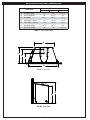
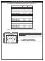
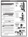
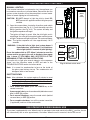
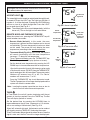
SPECIFICATIONS AND DIMENSIONS
Fig. 8-2 Side View
F
G
Fig. 8-1 Top View
A
B
C
D
E
Table 1 - Unit Dimensions
Description
Dimension
25 series 30 series 36 series
A. Unit Rear Width 21" 22" 24
1
/
2
"
B. Unit Front Width 28" 32
1
/
4
" 35"
C. Unit Depth 14
1
/
2
" 16
7
/
8
" 17
5
/
8
"
D. Vent Depth - Intake 12" 14
1
/
2
" 14
1
/
2
"
E. Vent Depth - Exhaust 7
7
/
8
" 10
1
/
4
" 10
1
/
4
"
F. Unit Rear Height 15
3
/
4
" 18
3
/
4
" 22"
G. Unit Front Height 19" 22" 25
1
/
2
"

9
SPECIFICATIONS AND DIMENSIONS (cont.)
Fig. 9-1 Front View (3 sided surround model) Fig. 9-2 Front View (4 sided surround model)
B
A
Fig. 9-3
Side View
C
DD
E
B
A
C
DD
C
Description
ABCDE
25 series
Surround 3-sided, small 34
3
/
8
" 22
1
/
2
"5" 4
3
/
4
"1
1
/
2
"
Surround 3-sided, medium 37
3
/
8
" 25
1
/
4
"7
3
/
4
"6
1
/
4
"1
1
/
2
"
Surround 3-sided, large 40
3
/
8
" 28" 10
1
/
2
"7
3
/
4
"1
1
/
2
"
Surround 4-sided, small 34
3
/
8
" 27" 4
3
/
4
"4
3
/
4
"1
1
/
2
"
Surround 4-sided, medium 37
3
/
8
" 30" 6
1
/
4
"6
1
/
4
"1
1
/
2
"
30 series
Surround 3-sided, small 38
3
/
8
" 25
1
/
2
"5
1
/
4
"4
1
/
2
"1
1
/
2
"
Surround 3-sided, medium 41
3
/
8
" 28" 6
1
/
4
"7
1
/
2
"1
1
/
2
"
Surround 3-sided, large 44
3
/
8
" 31" 7
3
/
4
" 10
1
/
2
"1
1
/
2
"
Surround 4-sided, small 38
3
/
8
" 30" 4
3
/
4
"4
3
/
4
"1
1
/
2
"
Surround 4-sided, medium 41
3
/
8
" 33" 6
1
/
4
"6
1
/
4
"1
1
/
2
"
36 series
Surround 3-sided, small 43
3
/
8
" 30" 6" 5
3
/
4
"1
1
/
2
"
Surround 3-sided, medium 45
3
/
8
" 32" 8" 6
3
/
4
"1
1
/
2
"
Surround 3-sided, large 49
3
/
8
" 35" 11" 8
3
/
4
"1
1
/
2
"
Surround 4-sided, small 43
3
/
8
" 33" 4
1
/
2
"5
3
/
4
"1
1
/
2
"
Surround 4-sided, medium 45
3
/
8
" 36" 6" 6
3
/
4
"1
1
/
2
"
Table 2 - Surround Kit Dimensions

10
SPECIFICATIONS AND DIMENSIONS (cont.)
Fig. 10-1 Insert in Fireplace Opening
G
F
(Direct vent insert)
• F x G represents fi replace opening
• Shaded area represents gap created
• Surround is designed to overlay fi replace opening a
minimum of 1"
* To complete your insert installation, a matching metal surround
is required to cover the gap between the insert and your existing
fi replace opening. Available in a black fi nish, choose from three
fi xed, non-adjustable 3-sided sizes. If your fi replace opening is
raised and fl ush with the wall; you may choose from two fi xed
dimension 4-sided surrounds. Consult Table 3 for assistance.
(gap in fi replace)
TO DETERMINE THE APPROPRIATE SURROUND FOR YOUR SETUP* :
Recommended surround
F max G max
25 series
Surround 3-sided, small 32
3
/
8
" 21
1
/
2
"
Surround 3-sided, medium 35
3
/
8
" 24
1
/
4
"
Surround 3-sided, large 38
3
/
8
" 27"
Surround 4-sided, small 32
3
/
8
" 19
3
/
4
"
Surround 4-sided, medium 35
3
/
8
" 24
1
/
4
"
30 series
Surround 3-sided, small 36
3
/
8
" 24
1
/
2
"
Surround 3-sided, medium 39
3
/
8
" 27"
Surround 3-sided, large 42
3
/
8
" 30"
Surround 4-sided, small 36
3
/
8
" 24
1
/
4
"
Surround 4-sided, medium 39
3
/
8
" 25
3
/
4
"
36 series
Surround 3-sided, small 41
3
/
8
" 29"
Surround 3-sided, medium 43
3
/
8
" 31"
Surround 3-sided, large 47
3
/
8
" 34"
Surround 4-sided, small 41
3
/
8
" 27
1
/
2
"
Surround 4-sided, medium 43
3
/
8
" 29"
Table 3 - Recommended Surround (based upon fi replace opening, see Fig. 10-1)

11
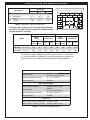
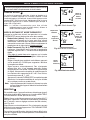
SPECIFICATIONS AND DIMENSIONS (cont.)
Fig. 11-1 Minimum Fireplace Dimensions
A
B
C
D
* For elevations above 2,000 feet, the BTU rate of the unit is reduced by
4% for each additional 1,000 feet. To install the unit above an elevation of
2,000 feet, you must use proper orifi ces based on the de-rated BTU.
* If exhaust collar on direct vent insert and fi replace damper
do not line up, add 3 inches to minimum fi replace height
to allow offsets of vent pipe.
Description
Dimension
25 series 30 series 36 series
A. Front Width 30
1
/
2
" 35" 38"
B. Rear Width 21
1
/
2
" 22
1
/
2
" 26"
C. Depth 15
1
/
2
" 18
1
/
2
" 19
1
/
2
"
D. Height * 20" 22
1
/
2
" 26"
Table 4 - Minimum Fireplace Dimensions
Model
Natural Gas Propane Gas
BTU
Rating
Orifi ce Size
BTU
Rating
Orifi ce Size
High
setting
Low
setting
Front Rear
High
setting
Low
setting
Front Rear
25 series
(0-2000 FT)
* 25k 16k #40 - 20k 14k #55 -
30 series
(0-2000 FT)
* 32k 9k #47 #45 29k 10k #58 #56
36 series
(0-2000 FT)
* 40k 11k #47 #39 33k 9k #57 #55
Remote Transmitter
Supply voltage
4.5 VDC
(three 1.5 V AAA batteries)
Ambient temperature ratings 32 - 122 °F (0-50 °C)
Radio frequency 433 MHz
Main Control Module
Input voltage / frequency 120 VAC / 60 Hz / .80 A
Backup power
6.0 VDC
(four 1.5 V AA batteries)
Ambient temperature ratings 32 - 140 °F (0-60 °C)
Radio frequency 433 MHz
Light / Fan
Input voltage / power consumption 120 VAC / 20 W
Input voltage / frequency / current 120 VAC / 60 Hz / .40 A
Table 5 - BTU Ratings and Orifi ce Sizes
Table 6 - Technical Data Specifi cations

12
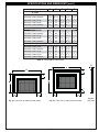
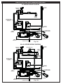
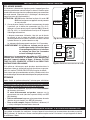
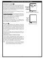
SPECIFICATIONS AND DIMENSIONS (cont.)
25 SERIES WIRING DIAGRAM
Fig. 12-1
MAIN VALVE
(NAT/LP)
TC MODULE
LEARN BUTTON
MAIN
BURNER
LIGHT
MAIN
HARNESS
BLOWER
ON/OFF
SWITCH
BATTERY PACK
6V DC BATTERY
BACKUP
TC PILOT
(NAT/LP)
POWER CORD
120 VAC SUPPLY
MAIN
MODULE
30 & 36 SERIES WIRING DIAGRAM
Fig. 12-2
MAIN VALVE
(NAT/LP)
TC MODULE
LEARN BUTTON
FRONT
BURNER
LIGHT
MAIN
HARNESS
BLOWER
ON/OFF
SWITCH
BATTERY PACK
6V DC BATTERY
BACKUP
TC PILOT
(NAT/LP)
POWER CORD
120 VAC SUPPLY
MAIN
MODULE
REAR
BURNER
SOLENOID VALVE

13
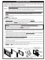
MINIMUM CLEARANCES
All minimum clearances must be met and maintained at all times. The clearances shown below include any
adjacent walls, spacers, standoffs, and any projections such as shelves, window sills, or fi replace mantels. They
also include any combustible decorations/items. Any fi nishing on the mantel must be heat resistant.
TOOLS REQUIRED
The following are the minimum tools required for the installation of your direct vent insert. Additional tools may
be required for your individual installation.
• 2 assemblers recommended
• rope
• measuring tape
• marker
• appropriate tools for gas supply
and electrical install
• reciprocating saw
• Mill-PAC hi temp. sealant
• cordless drill
• drill bits and drivers
• Phillips screwdriver (small & medium size)
•
5
/
16
" &
7
/
16
" nut drivers
•
7
/
16
" open-end wrench
• utility knife
• tin snip / hacksaw
Fig. 13-1 Minimum Clearances
A
B
C
Mantel - 12" Depth
Combustible Trim or Mantel Depth of 8" or less
FRONT VIEW TOP VIEW
D
SIDE VIEW
8"
12"
B
C
Table 7 - Minimum Clearances
Description
Dimension
25 series 30 series 36 series
A. Clearance required from the side edge of
the insert to combustibles or side wall
7" 7" 7"
B. Clearance required from the top edge of
the insert to combustibles or 8" mantel
16" 16" 16"
C. Clearance required from the top edge of
the insert to combustibles or 12" mantel
22" 22" 22"
D. Clearance required in front of insert to
allow door to fully open
35" 39" 44"

14
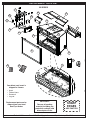
REPLACEMENT PARTS LIST
Robert H. Peterson Co. • 14724 East Proctor Avenue, • City of Industry, CA 91746
IMPORTANT
Remove all packing
material (including any
protective coatings) and
discard prior to use.
Your direct vent insert is
shipped in 4 boxes:
• Insert
• Firebox liners
• Surround
• Log set
Replacement parts can be
ordered from your local
Real Fyre dealer.
SHARP
EDGES
USE CAUTION
25 SERIES
15
6
16
14
8
21
13
5
1
24
25
4
9
10
11
2
12
18
19
17
22

15
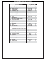
REPLACEMENT PARTS LIST (cont.)
25 SERIES
Item Description Part No. Qty.
1. Control valve (Nat) DV-30-701 1
or Control valve (LP) DV-30-702 1
2. Burner assembly DV-25-703 1
3. Burner orifi ce (Nat)* 3001-40-1 1
or Burner orifi ce (LP)* 3001-55-1 1
4.
or
Pilot assembly (Nat)
Pilot assembly (LP)
DV-25-716
DV-25-716P
1
1
5. Fan assembly DV-30-706 1
6. Grate DV-25-707 1
7.
Light bulb assy *
(120 VAC / 20 W bulb & gaskets)
DV-30-708 1
8. Glass panel assembly DV-25-900 1
9. Top fi rebox liner DV-25-918 1
10. 3-position mode switch SW-13 1
11. Learn button SW-12 1
12. Lintel DV-25-902 1
13. Spring door latch DV-30-910 2
14.
Remote kit
(includes remote transmitter, batteries, wall
mount remote holder, anchors, and screws)
DV-30-723 1
15. Air fl ow screen DV-25-710 1
16. Support leg (set of 4) DV-30-911 1
17. Main control module DV-30-714 1
18. Thermocouple module THM-01 1
19. Battery box BAT-02 1
20. Wire harness kit* DV-30-715 1
21. Vent adapter plate DV-25-912 1
22. Retention bracket DV-25-919 1
23. Wire hook* DV-30-717 1
24. Glowing embers EM-10 1
25. Bryte coals EM-11 1
*
Not shown

16
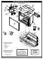
Robert H. Peterson Co. • 14724 East Proctor Avenue, • City of Industry, CA 91746
IMPORTANT
Remove all packing
material (including any
protective coatings) and
discard prior to use.
Your direct vent insert is
shipped in 4 boxes:
• Insert
• Firebox liner
• Surround
• Log set
Replacement parts can be
ordered from your local
Real Fyre dealer.
30 model shown
SHARP
EDGES
USE CAUTION
REPLACEMENT PARTS LIST (cont.)
30 & 36 SERIES
17
8
18
16
10
7
1
30
29
27
3
28
6
2
24
15
11
12
13
21
22
20
19
14
25

17
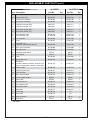
REPLACEMENT PARTS LIST (cont.)
30 SERIES 36 SERIES
Item Description Part No. Qty. Part No. Qty.
1. Control valve (Nat) DV-30-701 1 DV-30-701 1
or Control valve (LP) DV-30-702 1 DV-30-702 1
2. Front burner assembly DV-30-703 1 DV-36-703 1
3. Rear burner assembly DV-30-704 1 DV-36-704 1
4. Front burner orifi ce (Nat)* 3001-47-1 1 3001-47-1 1
or Front burner orifi ce (LP)* 3001-58-1 1 3001-57-1 1
5. Rear burner orifi ce (Nat)* 3001-45-1 1 3001-39-1 1
or Rear burner orifi ce (LP)* 3001-56-1 1 3001-55-1 1
6.
or
Pilot assembly (Nat)
Pilot assembly (LP)
DV-30-716
DV-30-716P
1
1
DV-30-716
DV-30-716P
1
1
7. Fan assembly DV-30-706 1 DV-30-706 1
8. Grate DV-30-707 1 DV-36-707 1
9.
Light bulb assy *
(120 VAC / 20 W bulb & gaskets)
DV-30-708 1 DV-30-708 1
10. Glass panel assembly DV-30-900 1 DV-36-900 1
11. Top fi rebox liner DV-30-918 1 DV-36-918 1
12. 3-position mode switch SW-13 1 SW-13 1
13. Learn button SW-12 1 SW-12 1
14. Lintel DV-30-902 1 DV-36-902 1
15. Spring door latch DV-30-910 2 DV-30-910 2
16.
Remote kit
(includes remote transmitter, batteries, wall
mount remote holder, anchors, and screws)
DV-30-723 1 DV-30-723 1
17. Ember screen DV-30-710 1 DV-30-710 1
18. Support leg (set of 4) DV-30-911 1 DV-30-911 1
19. Valve split fl ow DV-30-712 1 DV-30-712 1
20. Main control module DV-30-714 1 DV-30-714 1
21. Thermocouple module THM-01 1 THM-01 1
22. Battery box BAT-02 1 BAT-02 1
23. Wire harness kit* DV-30-715 1 DV-30-715 1
24. Vent adapter plate DV-30-912 1 DV-30-912 1
25. Retention bracket DV-25-919 1 DV-25-919 1
26. Wire hook* DV-30-717 1 DV-30-717 1
27. Front baffl e DV-30-718 1 n/a -
28. Rear baffl e DV-30-719 1 n/a -
29. Glowing embers EM-10 1 EM-10 2
30. Bryte coals EM-11 1 EM-11 2
*
Not shown

18
1
2
3
4
5
6
Boston Buff Brick
fi rebox liners shown
25 SERIES 30 SERIES 36 SERIES
Item Description Part No. Qty. Part No. Qty. Part No. Qty.
1. Left liner (Boston Buff Brick) DVP-25-800 1 DVP-30-800 1 DVP-36-800 1
or
or
Left liner (Herringbone Brick)
Left liner (Black Porcelainized)
DVP-25-801
DVP-25-811
1
1
DVP-30-801
DVP-30-811
1
1
DVP-36-801
DVP-36-811
1
1
2. Right liner (Boston Buff Brick) DVP-25-802 1 DVP-30-802 1 DVP-36-802 1
or
or
Right liner (Herringbone Brick)
Right liner (Black Porcelainized)
DVP-25-803
DVP-25-812
1
1
DVP-30-803
DVP-30-812
1
1
DVP-36-803
DVP-36-812
1
1
3. Rear liner (Boston Buff Brick) DVP-25-804 1 DVP-30-804 1 DVP-36-804 1
or
or
Rear liner (Herringbone Brick)
Rear liner (Black Porcelainized)
DVP-25-805
DVP-25-813
1
1
DVP-30-805
DVP-30-813
1
1
DVP-36-805
DVP-36-813
1
1
4. Left fl oor panel DVP-25-808 1 DVP-30-808 1 DVP-30-808 1
5. Right fl oor panel DVP-25-809 1 DVP-30-809 1 DVP-30-809 1
6. Front fl oor panel DVP-25-810 1 DVP-30-810 1 DVP-36-810 1
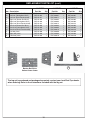
REPLACEMENT PARTS LIST (cont.)
The log set is purchased and packaged separately; contact your local Real Fyre dealer
when ordering. Refer to the instructions included with the log set.

19
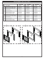
REPLACEMENT PARTS LIST (cont.)
25 SERIES 30 SERIES 36 SERIES
Item Description Part No. Qty. Part No. Qty. Part No. Qty.
1.
or
or
3-sided surround assembly, small
3-sided surround assembly, medium
3-sided surround assembly, large
DVS-25-3A
DVS-25-3B
DVS-25-3C
1
1
1
DVS-30-3A
DVS-30-3B
DVS-30-3C
1
1
1
DVS-36-3A
DVS-36-3B
DVS-36-3C
1
1
1
2. Surround screen DV-25-913 1 DV-30-913 1 DV-36-913 1
3. 3-sided surround door DV-25-914 1 DV-30-914 1 DV-36-914 1
4.
or
or
3-sided surround fascia, small
3-sided surround fascia, medium
3-sided surround fascia, large
DV-25-915A
DV-25-915B
DV-25-915C
1
1
1
DV-30-915A
DV-30-915B
DV-30-915C
1
1
1
DV-36-915A
DV-36-915B
DV-36-915C
1
1
1
5.
or
4-sided surround assembly, small
4-sided surround assembly, medium
DVS-25-4A
DVS-25-4B
1
1
DVS-30-4A
DVS-30-4B
1
1
DVS-36-4A
DVS-36-4B
1
1
6. Surround screen DV-25-913 1 DV-30-913 1 DV-36-913 1
7. 4-sided surround door DV-25-916 1 DV-30-916 1 DV-36-916 1
8.
or
4-sided surround fascia, small
4-sided surround fascia, medium
DV-25-917A
DV-25-917B
1
1
DV-30-917A
DV-30-917B
1
1
DV-36-917A
DV-36-917B
1
1
1
2
3
4
5
6
7
8

20
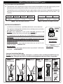
INSTALLATION REQUIREMENTS
Installation must be done by a qualifi ed professional service technician.
Prior to installation ensure that all specifi cations, dimensions, and minimum clearances stated in this
manual are observed. You must read all warnings and safety information, and understand all of the
information in this manual. All of these installation requirements must be observed and met.
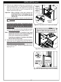
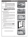
FIREPLACE REQUIREMENTS
A. This appliance must be vented directly to the outside in accordance with the current edition of the National
Fuel Gas Code (NFPA 54 in U.S.A. and CAN/CSA B149.1 in Canada) and must never be attached to a
chimney serving a separate solid fuel burning appliance. This appliance is designed to be installed into an
existing masonry fi replace (built to UBC 37 or ULC S628 standards) or factory built solid fuel, wood, burning
fi replace (listed to UL 127 or ULC S610) only. All exhaust gases must be vented outside the structure.
Combustion air is drawn from outside the structure.
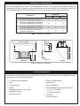
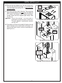
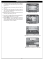
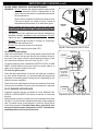
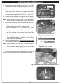
B. Cutting any sheet metal parts of the fi replace in which the gas fi replace insert is to be installed is prohibited,
with the exception of the fi rebox fl oor. The metal fi rebox fl oor may be removed/altered to allow additional
room for installation of the insert. Note: a minimum 5" clearance is required between the fi replace fl oor and
the insert. The clearance may be provided by lowering the fi rebox fl oor, placing bricks, etc. See Fig. 20-2.
C. If the factory-built fi replace has no gas access hole(s) provided, an access hole of 1.5 in (37.5 mm) or less
may be drilled through the lower sides or bottom of the fi rebox in a proper workmanship like manner. This
access hole must be plugged with non-combustible insulation after the gas supply line has been installed.
Si le foyer préfabriqué ne comporte pas d’orifi ces d’amenée du gaz, un orifi ce d’au plus 37,5 mm (1,5 po)
peut être pratiqué, selon les règles de l’art, dans la partie inférieure des parois ou au fond de la chambre
de combustion. Cet orifi ce doit être obturé au moyen d’isolant incombustible une fois la conduite de gaz
en place.
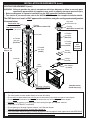
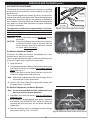
D. The fi replace fl ue damper must be removed for installation of the gas fi replace insert.
E. The fi replace and fi replace chimney must be completely clean. Brush and vacuum all interior surfaces so
that no embers, soot, or loose combustion deposits can be drawn into the heat circulation fan and blown
into the living area. The fi replace and fi replace chimney must be in good working order and constructed of
non-combustible materials. Inspect chimney clean-outs for proper fi t and seal. If any portion of the chimney
system shows signs of structural or mechanical weaknesses, the faulty portion must be repaired or replaced
prior to installing this appliance.
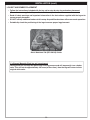
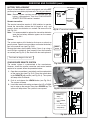
F. Firebox liners, glass panels, screen rails, screen mesh and log grates may be removed from the fi replace
(as needed) before installing the gas fi replace insert. Smoke shelves, shields and baffl es may be removed
if attached by mechanical fasteners. Any parts that are removed must be retained for later reinstallation to
restore the fi replace to its original operating condition. The removal of any part must not alter the integrity
of the outer shell of the pre-fab fi replace cabinet in any way. If any parts are removed (or altered) from the
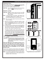
existing fi replace, a Warning Label (see Fig. 20-1 below) must be affi xed inside the fi replace fi rebox. The
label must be visible upon removal of the direct vent insert.
Fig. 20-1 Fireplace Warning Label (see F above)
WARNING
THIS FIREPLACE HAS BEEN ALTERED
TO ACCOMODATE A FIREPLACE INSERT
AND SHOULD BE INSPECTED BY A QUALIFIED PERSON
PRIOR TO RE-USE AS A CONVENTIONAL FIREPLACE.
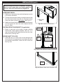
Fig. 20-2 Pre-fab fi replace fl oor height adjustment
Pre-fab
fi replace
Fireplace
fl oor
Insert resting
at new
lowered level
(i.e. lowering of
fl oor, placing
bricks, etc.)
Combustible
fl oor
Min. 5"
clearance
La page est en cours de chargement...
La page est en cours de chargement...
La page est en cours de chargement...
La page est en cours de chargement...
La page est en cours de chargement...
La page est en cours de chargement...
La page est en cours de chargement...
La page est en cours de chargement...
La page est en cours de chargement...
La page est en cours de chargement...
La page est en cours de chargement...
La page est en cours de chargement...
La page est en cours de chargement...
La page est en cours de chargement...
La page est en cours de chargement...
La page est en cours de chargement...
La page est en cours de chargement...
La page est en cours de chargement...
La page est en cours de chargement...
La page est en cours de chargement...
La page est en cours de chargement...
La page est en cours de chargement...
La page est en cours de chargement...
La page est en cours de chargement...
La page est en cours de chargement...
La page est en cours de chargement...
La page est en cours de chargement...
La page est en cours de chargement...
La page est en cours de chargement...
La page est en cours de chargement...
La page est en cours de chargement...
La page est en cours de chargement...
La page est en cours de chargement...
La page est en cours de chargement...
La page est en cours de chargement...
La page est en cours de chargement...
La page est en cours de chargement...
La page est en cours de chargement...
La page est en cours de chargement...
La page est en cours de chargement...
-
 1
1
-
 2
2
-
 3
3
-
 4
4
-
 5
5
-
 6
6
-
 7
7
-
 8
8
-
 9
9
-
 10
10
-
 11
11
-
 12
12
-
 13
13
-
 14
14
-
 15
15
-
 16
16
-
 17
17
-
 18
18
-
 19
19
-
 20
20
-
 21
21
-
 22
22
-
 23
23
-
 24
24
-
 25
25
-
 26
26
-
 27
27
-
 28
28
-
 29
29
-
 30
30
-
 31
31
-
 32
32
-
 33
33
-
 34
34
-
 35
35
-
 36
36
-
 37
37
-
 38
38
-
 39
39
-
 40
40
-
 41
41
-
 42
42
-
 43
43
-
 44
44
-
 45
45
-
 46
46
-
 47
47
-
 48
48
-
 49
49
-
 50
50
-
 51
51
-
 52
52
-
 53
53
-
 54
54
-
 55
55
-
 56
56
-
 57
57
-
 58
58
-
 59
59
-
 60
60


dans d''autres langues
Documents connexes
Autres documents
-
Essence ESS45 Installation And Operating Instructions Manual
-
R.H. Peterson realfyre G5 Series Le manuel du propriétaire
-
Superior Fireplaces DRI2000 Mode d'emploi
-
 Sierra Flame PALISADE-36-DELUXE Installation And Operating Instructions Manual
-
 Regency Fireplace Products Horizon HZI540EB Le manuel du propriétaire
-
 Regency Fireplace Products Horizon HZI540EB Le manuel du propriétaire
-
Pacific energy Broadway Installation And Operating Instructions Manual
-
NAPOLEON SGM3F3B4 Le manuel du propriétaire
-
IHP Superior Fireplaces DRC2033REN Mode d'emploi
-


