KitchenAid KHTU705RSS1 Le manuel du propriétaire
- Catégorie
- Hottes
- Taper
- Le manuel du propriétaire
Ce manuel convient également à

®itchenAid ®
(91.4cm)
et 36" (91,4cm)
avec
Table of Contents/Table des mati_res ............................................................................. 2
iMPORTANT: READ AND SAVE THESE iNSTRUCTiONS,
FOR RESiDENTiAL USE ONLY.
iMPORTANT : LIRE ET CONSERVER CES iNSTRUCTiONS,
POUR UTiLiSATiON RESmDENTmELLEUNiQUEMENT.
iMPORTANT:
Installer: Leave installation instructions with the homeowner,
Homeowner: Keep installation instructions for future reference.
Save installation instructions for local inspector's use,
iMPORTANT :
lnetallateur : Remettre les instructions d'installation au proprietaire.
PropriStaire : Conserver les instructions d'installation pour consultation ulterieure.
Conserver les instructions d'instatlation pour consultation par I'inspecteur local.
9763384

TABLEOF CONTENTS TABLEDES ' TIERES
RANGE HOOD SAFETY ............................... 2
iNSTALLATiON REQUIREMENTS ....................... 3
Tools and Parts ..................................... 3
Location Requirements ............................. 4
Venting Requirements .............................. 4
Electrical Requirements ............................. 5
INSTALLATION INSTRUCTIONS ........................ 6
Venting Options ................................... 6
Prepare Location .................................. 6
Change Hood to Rear Exhaust ....................... 7
install Range Hood ................................ 8
Make Electrical Connection .......................... 8
Optional Front Trim installation ....................... 9
install Filters ...................................... 9
Check Operation .................................. 9
RANGE HOOD USE ................................... 9
Range Hood Controls .............................. 9
RANGE HOOD CARE ................................ 10
Range Hood Lamps ............................... 10
Replacing Hood Lamps Fuse ....................... 10
Cleaning ........................................ 10
Accessories ..................................... 11
REQUESTING ASSISTANCE OR SERVICE .............. 11
RANGE HOOD WARRANTY ........................... 12
WIRING DIAGRAM .................................. 13
S#CURITE DE LA HOTTE DE CUISINI_:RE .............. 14
EXIGENCES D'INSTALLATION ........................ 16
Outillage et pi6ces .................................. 16
Exigences d'emplacement .......................... 16
Ex[gences concernant I'evacuation ................... 17
Specifications ebctriques .......................... 18
INSTRUCTIONS D'INSTALLATION ..................... 19
Options disponibles pour Ie circuit d'evacuation ........ 19
Preparation de Femplacement ....................... 19
Modification de Ia hotte pour evacuation par
I'arri_re (facultatif) ................................ 20
installation de Ia hotte de cu[s[n[_re .................. 21
Raccordement electrique ........................... 21
installation de Ia garniture de fagade
interchangeable (option) ........................... 22
installation des filtres .............................. 22
Contr61e du fonctionnement ........................ 22
UTIUSATION DE LA HOTTE DE CUISINI :RE............ 23
Commandes de la hotte de cuisini_re ................. 23
ENTRETIEN DE LA HOTTE DE OUISINI_:RE ............. 23
Lampes de la hotte de cuisini_re ..................... 23
Remplacement des fusibles des lampes de la hotte ..... 23
Nettoyage ....................................... 24
Accessoires ..................................... 24
ASSISTANCE OU SERVICE ........................... 25
GARANTIE DE LA HOTTE DE CUISINIERE .............. 26
SCHEMA DE CABLAGE .............................. 27
RANGEHOODSAFETY
Your safety and the safety of others are very important.
We have provided many important safety messages in this manual and on your appliance. Always read and obey all safety
messages.
This is the safety alert symbol.
This symbol alerts you to potential hazards that can kill or hurt you and others.
All safety messages will follow the safety alert symbol and either the word "DANGER" or "WARNING."
These words mean:
You can be killed or seriously injured if you don't immediately
follow instructions.
You can be killed or seriously injured if you don't follow
instructions.
All safety messages will tell you what the potential hazard is, tell you how to reduce the chance of injury, and tell you what can
happen if the instructions are not followed.

iMPORTANT SAFETY iNSTRUCTiONS
WARNING: TO REDUCE THE RiSK OF FIRE, ELECTRIC
SHOCK, OR iNJURY TO PERSONS, OBSERVE THE
FOLLOWING:
m Use this unit only in the manner intended by the
manufacturer, if you have questions, contact the
manufacturer.
m Before servicing or cieaning the unit, switch the power off at
the service panel disconnecting means to prevent power
from being switched on accidentalIy. When the service
disconnecting means cannot be locked, securely fasten a
prominent warning device, such as a tag, to the service
panel.
m installation work and electricaJ wiring must be done by
qualified person(s) in accordance with all applicable codes
& standards, including fire-rated construction.
m Sufficient air is needed for proper combustion and
exhausting of gases through the flue (chimney) of fuel
burning equipment to prevent backdrafting. Follow the
heating equipment manufacturer's guideline and safety
standards such as those published by the National Fire
Protection Association (NFPA), the American Society for
Heating, Refrigeration and Air Conditioning Engineers
(ASHRAE), and the local code authorities.
m When cutting or drilling into wall or ceiling; do not damage
electrical wiring and other utilities.
m Ducted systems must always be vented outdoors.
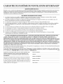
CAUTION: For general ventilating use only. Do not use
to exhaust hazardous or explosive materials and vapors.
CAUTION: To reduce risk of fire and to properly exhaust
air, be sure to duct air outside - do not vent exhaust air into
spaces within walls ceilings, attics, crawl spaces, or
garages.
WARNING: TO REDUCE THE RiSK OF FIRE, USE ONLY
METAL DUCTWORK.
WARNING: TO REDUCE THE RiSK OF A RANGE TOP
GREASE FIRE:
m Never leave the surface units unattended at high settings.
Boilovers cause smoking and greasy spillovers that may
ignite. Heat oils siowiy on low or medium settings.
m Always turn hood ON when cooking at high heat or when
flameing food (i.e. Crepes Suzette, Cherries Jubilee,
Peppercorn Beef Flamb@.
m Clean ventilating fans frequently. Grease shouId not be
allowed to accumulate on fan or filter.
m Use proper pan size. Always use cookware appropriate for
the size of the surface element.
WARNING: TO REDUCE THE RiSK OF iNJURY TO
PERSONS iN THE EVENT OF A RANGE TOP GREASE
FIRE, OBSERVE THE FOLLOWING: a
m SMOTHER FLAMES with a close fitting Iid, cookie sheet, or
other metal tray, then turn off the gas burner or electric
element. BE CAREFUL TO PREVENT BURNS. if the
flames do not go out immediately, EVACUATE AND CALL
THE FiRE DEPARTMENT.
m NEVER PiCK UP A FLAMING PAN - you may be burned.
m DO NOT USE WATER, including wet dishcloths or towels -
a vioIent steam explosion wilI result.
m Use an extinguisher ONLY if:
- You know you have a class ABC extinguisher, and you
already know how to operate it.
- The fire is small and contained in the area where it
started.
- The fire department is being called.
- You can fight the fire with your back to an exit.
aBased on "Kitchen Fire Safety Tips" published by NFPA.
m WARNING: To reduce the risk of fire or electrical shock,
do not use this fan with any solid-state speed control
device.
SAVE THESE iNSTRUCTiONS
INSTALLATIONREQUIREMENTS
Gather the required tools and parts before starting installation.
Read and follow the safety instructions provided with any tools
listed here.
Tools needed:
Level
Drill
11//, drill bit
Pencil
Pliers
Wire stripper or utility knife
Tape measure or ruler
Caulking gun and weatherproof caulking compound
Saber or keyhole saw
Duct tape
Flat-blade screwdriver
Metal snips
Phillips screwdriver
7 mm nut driver or socket
Parts supplied
Check that all parts are included.
4 screws
4 wall anchors
Damper
Parts needed
UL listed or CSA approved 1/2"(12.5 mm) strain reliefs (2)
Power supply cable
6" (15.2 cm) round wall or roof cap
6" (15.2 cm) metal vent system

IMPORTANT:Observeallgoverningcodesandordinances,
Itistheinsta/er'sresponsibilitytocomplywithinstallation
clearancesspecifiedonthemodel/serialratingplate,The
model/serialratingplateislocatedinsidetherangehoodon
therearwall.
Rangehoodlocationshouldbeawayfromstrongdraftareas,
suchaswindows,doorsandstrongheatingvents.
Cabinetopeningdimensionsthatareshownmustbeused.
Givendimensionsprovideminimumclearance.Consuityour
cooktop/rangemanufacturerinstallationinstructionsbefore
makinganycutouts.
Groundedelectricaloutletisrequired.See"Electrical
Requirements"section.
Thehoodisfactorysetforventedinstallations.For
recircuiatinginsta/ations,RecirculationKitPartNumber
4896565,includingventcoverand2charcoalfiltersare
availablefromyourdealer.
AIopeningsinceilingandwallwhererangehoodwillbe
installedmustbesealed.
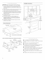
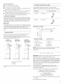
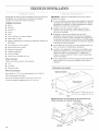
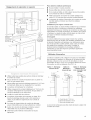
Productdimensions
57/s' (14,9 cm) dia,
exhaust collar
J J" Interchangeable
_f Front Trim
Vent and electrical openings and mounting screw locations
centerlne of 9V8"
5 x/s" exhaust collar
(14.9 cm) (23,2 cm)
dia,'_,
(10.0cm)
electrical
knockouts
(19,0 cm)
centerlne
of hood
installation clearances
bottom of hood to 70%d
(178,6 cm)
rain.
18" (45.7 cm) 76%d
rain, clearance (193.8 cm)
upper cabinet max,
to countertop to bottom of
cabinet frame
36" (91,4 cm)
countertop
height
[] Use a straight run or as few elbows as possible.
[] Do not terminate the vent system in an attic or other enclosed
area.
[] Do not use a 4" (10.2 cm) [aundry-type wal caps.
[] Vent system must terminate to the outside.
[] Use only a 6" (15.2 cm) round metal vent. Rigid metal vent is
recommended. Do not use plastic or metal foil vent.
[] The size of the vent shouid be uniform.
[] The vent system must have a damper, if roof or wall cap has a
damper, do not use damper suppled with the range hood.
[] Use duct tape to seaI a/ioints in the vent system.
[] Use cauiking to seal exterior wail or roof opening around the
cap.
[] Determine which venting method is best for your application.

ForBestPerformance:
[] Donotinstall2elbowstogether.
[] Usenomorethanthree90°elbows.
[] Ifanelbowisused,installitasfarawayaspossiblefromthe
hood'sventmotorexhaustopening.
[] Makesurethereisaminimumof24"(61cm)ofstraightvent
betweentheelbowsifmorethanoneelbowisused.
[] Thelengthofventsystemandnumberofelbowsshouldbe
kepttoaminimumtoprovideefficientperformance.
ColdWeatherlnetalmatione
Anadditionalbackdraftdampershouldbeinstalledtominimize
backwardcoldairflowandanonmetallicthermalbreakinstalled
tominimizeconductionofoutsidetemperaturesaspartofthe
ventsystem.Thedampershouldbeonthecoldairsideofthe
thermalbreak.
MakeupAir
Localbuildingcodesmayrequiretheuseofmakeupairsystems
whenusingventilationsystemsgreaterthanspecifiedCFMofair
movement.ThespecifiedCFMvariesfromlocaletolocale.
ConsultyourHVACprofessionalforspecificrequirementsinyour
area,
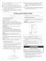
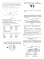
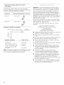
Venting methods
This range hood is factory set for vented installations. Vent
system can terminate through either the roof or wall. A
6" (15.2 cm) round vent system must be used. The vent system
length should not exceed 35 ft (10.7 m).
Option 1 - Option 2
Roof venting Wall venting
Option 3 -
Rear exhaust
wall venting
A .....
A. 6" (15.2 cn'_)round venting
B. Roof cap
C. Waftcap
The exhaust collar can also be directed to vent out the rear of the
hood.
Calculating Vent System Length
To calculate the length of the system you need, add the
equivalent feet (meters) for each vent piece used in the system.
Vent piece 6" (15.2 cm) round
45° elbow 2.5 ft (0.8 m) _ ....
i
90° elbow 5.0 ft (1.5 m)
E×ample vent system
90° elbow _- 6 ft, (1.8 m)_'_ wall cap
\ /
2fL
(0_6rn)
Maximum _ength = 35 ft (10.7 m)
1-90 °elbow = 5 ft (1.5 m)
8 ft (2.4 m) straight = 8 ft (2.4 m)
1 - wall cap = 0 ft (0 m)
System length = 13 ft (3.9 m)
NOTE: Flexible vent is not recommended. Flexible vent creates
back pressure and air turbulence that greatly reduce
performance.
IMPORTANT.- Observe all governing codes and ordinances. Save
installation instructions for electrical inspector's use.
it is the customer's responsibility to contact a qualified electrical
installer, and to assure that the electrical installation is adequate
and in conformance with National Electrical Code, ANSI/NFPA 70
(latest edition), or CSA Standards C22.1-94, Canadian Electrical
Code, Part 1 and C22.2 No. 0-M91 (latest edition) and all local
codes and ordinances.
if codes permit and a separate ground wire is used, it is
recommended that a qualified electrician determine that the
ground path is adequate.
A copy of the above code standards can be obtained from:
National Fire Protection Association
One Batterymarch Park, Quincy, MA 02269
CSA international
8501 East Pleasant Valley Road
Cleveland, OH 44131-5575
A 120-volt, 60-Hz, AC-only, 15 amp, fused electrical circuit is
required.
Do not ground to a gas pipe.

[] Checkwithaqualifiedelectricianifyouarenotsurerange
hoodisproperlygrounded.
[] Donothaveafuseintheneutralorgroundcircuit.
[] Therangehoodmustbeconnectedwithcopperwireonly.
[] Therangehoodshouldbeconnecteddirectlytothefused
disconnect(orcircuitbreaker)boxthroughflexiblearmoredor
nonmetallicsheathedcoppercable.
[] Wiresizes(copperwireonly)andconnectionsmustconform
withtheratingoftheapplianceasspecifiedonthemodel/
serialratingplate.
[] WiresizesmustconformtotherequirementsoftheNational
ElectricalCode,ANSI/NFPA70(latestedition),orCSA
StandardsC22.1-94,CanadianElectricalCode,Part1and
C22.2No.0-M91(latestedition)andalllocalcodesand
ordinances.
[] A1/2"(12.7mm)ULlistedorCSAapprovedstrNnreliefmust
beprovidedateachendofthepowersupplycable(atthe
rangehoodandatthejunctionbox).
iNSTALLATiONiNSTRUCTiONS
GeneraJ venting installation
For vented instalmations:
Make necessary cuts in the wall for vent fittings.
NOTE: The hood exhaust may be directed out the rear of the
hood by removing the motor assembly and rotating it so the
exhaust collar is located on the rear of the hood. If this is desired,
see "Change Hood to Rear Exhaust" section to change the
exhaust direction.
IMPORTANT: Make sure the vent system is installed before
installing range hood.
For reeireumating installations:
A vent system and vent grill (not provided) that directs the
recirculated air back into the room either through the soffit or
through the cabinet top is required. Use Recirculation Kit Part
Number 4396565. For ordering information, see "Assistance or
Service."
IMPORTANT: If venting through the cabinet top, do not
terminate the exhaust into dead air space such as an attic or
enclosed soffit.
When venting through the soffit, assemble the vent system (not
provided) you will use over the exhaust collar, but do not attach
the vent system yet.
NOTE: The vent system can exhaust out the front of the soffit or
be rotated to exhaust out the side or end of the soffit.
Venting through the soffit
1. On aflat surface with a protective covering, assemble the
vent system you will use (not provided) over the exhaust
collar, but do not attach the vent system yet.
NOTE: The vent system can exhaust out the front of the soffit
or be rotated to exhaust out the side or end of the soffit.
2. Measure distance "A" (from top of hood to centerline of 6"
[15.2 cm] round vent). Mark the distance "A" on soffit.
3. Mark and cut a 6" (15.2 cm) round vent opening.
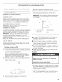
Venting through cabinet top
1. Mark the location where vent cover will be installed in the
cabinet top and cut a 6" (15.2 cm) round vent opening for the
vent cover
IMPORTANT: Do not terminate exhaust into a dead air space
such as an attic or enclosed soffit.
C
A, Vent system D. Ceiling or soffit
B. Vent cover E, Hood
C. Cabinet top
[] For vented installations, it is recommended that the vent
system be installed before hood is installed.
[] Do not cut a joist or stud unless absolutely necessary. If a
joist or stud must be cut, then a supporting frame must be
constructed.
[] Before making cutouts, make sure there is proper clearance
within the ceiling or wall for vent fittings.
[] Check that all the installation parts and the box with filters
have been removed from the shipping carton.
Preparation
1. If possible, disconnect power and/or gas supply and move
freestanding or slide-in range from cabinet opening to
provide easier access to rear wall.
2. Select a flat surface for assembling the hood. Cover that
surface with a protective covering such as a blanket or
cardboard during assembly.

Excessive Weight Hazard
Use two or more people to move and install
range hood.
Failure to do so can result in back or other injury.
3. Using 2 or more people, slowty Iift the range hood onto the
protected surface=
4o Tip hood on its back and remove the metal filters. Push tab
back to release locking pin, pull down and forward. Repeat
with other filter=
5o Remove hardware package.
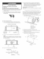
6o Add wood filler strips as needed to cabinet bottom. Drill
3 H
4, Y_6(4=8mm) clearance holes for hood mounting screws.
13's/4"(34,9 cm) -30" (76.2 cm) model
163/4,,(42,5 cm) -36" (91_4 cm) model
' / _d< \
I
wood filler strips wall s/re" (4,8 ram)
(recessed cabinet 1:_/_"
clearance holes
bottoms only) (4_8 cm)
7,
Cut a 6_/2'' (16.5 cm) diameter hole in cabinet bottom as
shown.
NOTE: If you are changing the hood to rear exhaust, skip this
step. See "Change Hood to Rear Exhaust" section to change
the exhaust direction.
I
61/2` (16.5 cm) dia, hole i.... centerhne
9. Run wire through hole in accordance with the National
Electrical Code or CSA Standards and local codes and
ordinances= There must be enough power supply cable from
the fused disconnect (or circuit breaker) box to make the
connection in the range hood's electrical box=
10. Use caulking to seal all openings=
iMPORTANT: Do not turn on power until installation is complete=
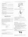
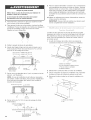
The hood comes from the factory with the exhaust collar on top
of the hood. The hood exhaust may be directed out the rear of
the hood through the exhaust collar. If you desire to have the
hood exhaust out the rear, follow the procedure below.
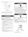
1. From inside the hood, remove the screw holding the ground
wire to the blower motor.
O
2=
3,
B j
c
A. Blowermotor
B.Groundwirescrew
C.Blowermotorplug
D.Retainingclip
Unplug the wire attached at the blower motor.
Remove the blower motor wire and ground wire from the
retaining clip on the hood.
Turn the hood over and remove the screws holding the
exhaust blower assembly to the hood.
8,
wall 315/1(;'
(10.Ocm)
Cut a 11/4'' (32 cm) hole for power supply cable.
upper cabinet or soffit
mounting surface u
A, Blower motor assembly
B, Screws
centerline ....... ul _1
power supply s/le"
cable hole in wall

5. ii!y}is_ii_igeiil}!30_ii:{:!:rlii:i_i!i! ,iil}g,liiiiiiii_i!_Ci:iOS
Rotate the blower assembly so that the exhaust collar is
facing out the back of the hood,
A, _?
t
I
A.Exhaustblowerassembly
B,Screws
C.Exhaustcollar
6, Replace the screws holding the blower assembiy to the hood,
7, Plug the blower motor wire back into the blower motor,
8, Screw the ground wire back onto the blower motor,
Electdcam Shock Hazard
Disconnect power before servicing,
Repmace aH parts and panels before operating,
Failure to do so can resumt in death or eJectricam shock.
1, Disconnect power at the circuit breaker of fused circuit box.
2, Connect the white wire of the power supply cable with the
white lead in the range hood using a twist-on connector,
3, Connect the black wire of the power suppiy cable with the
black lead in the range hood using a twist-on connector.
Excessive Weight Hazard
Use two or more people to move and install
range hood.
Failure to do so can result in back or other injury.
1, Remove the terminal box cover (located on back wall of hood)
from the hood, Remove the power supply cable knockout
using a flat-blade screwdriver.
Attach strain relief in power supply cable opening so that
clamping screws are inside of range hood. Tip hood back to
its bottom surface.
2, if roof or wall cap does not have a damper, attach damper to
exhaust opening on top of the range hood using 2 small
screws from hardware package.
3, Place the range hood mounting screws close to the holes in
the cabinet bottom,
4, Lift range hood into ptace while feeding wiring through strain
relief.
5. insert the screws through the clearance holes and start them
into the hood. Then, tighten screws securely.
6. Connect vent system, for either vented or recirculating, to
range hood.
7. Seal all joints with duct tape.
8. For recircutating installations, install the vent cover (not
provided) included in Recirculation Kit Part Number 4396565
in soffit or cabinet top vent opening.
Electdcam Shock Hazard
EmectdcaHy ground blower.
Connect ground wire to green ground screw in
terminam box.
Failure to do so can resumt in death or eJectdcam shock.
4, Connect the green power supply ground wire to the unused,
green ground screw.
A .........
A. Green ground screw
B, Hood wiring
C, White wires
D
'F
D. Fwist-onconnectors
E,Blackwires
F.Powersupplycable
5, Tighten strain relief screws.
6, Replace the terminal box cover.

ThishoodcomesstandardwithanArchitect_seriesstainless
steelfronttrimpiece.Toreplacethestandardfronttrimpiecewith
anoptionalpurchasedfronttrimpiece:
1=Reachinsidethefrontofthehoodandlocateahexnut
approximately3"(7.6cm)infrombothoutsideedges.
2=Removethe7mmhexnuts.
A.Hood
B.Hexnut
C. Trimpiece
3= Pull the trim piece straight out.
4= Insert the studs on the back of the new trim piece through the
holes in the front of the hood.
5= Replace the hex nuts and tighten securely.
Removable Interchangeable Front Trim Part Numbers:
30" (76,2 ore} models
Color Series Part Number
White Architect _ 8212462
Black Architect _ 8212463
Biscuit Architect _" 8212461
Stainless Pro Lind ") 8212464
Meteorite Pro Lind _ 8212465
36" (91=4cm) models
i i
Color Series Part Number
White Architect _= 8212467
Black Architect _ 8212468
Biscuit Architect _ 8212466
Stainless Pro Line'_ 8212469
Meteorite Pro Line'_ 8212470
:: t
For recirculating instalations only, install the charcoal filters
included in Recirculation Kit Part Number 4396565. Place the
charcoal filter against the blower cover and rotate to the right
(clockwise) to attach to cover. Repeat with other charcoal filter.
A,Filter
2= Replace metal filter. Place back edge of metal filter into
channel at rear of hood. Push filter up while pushing tab back.
\
\,
When filter is in place, release tab. Locking pin w/I hold filter
Jnplace.
2=
Check operation of the range hood by turning on the power.
The range hood controls are located in front on the underside
of the range hood.
B
A.Controls
B,Filters
3. Move the/ght switch to "1" position. The light should turn on.
4. Move blower switch to "1" position. The blower should
operate.
5. Move the blower speed switch to "1" position for low speed,
"2" position for medium speed or "3" position for high speed.
6. Move blower and light switches to "0" position to turn blower
and light off.
7. Ifthe range hood does not operate, check to see whether a
circuit breaker has tripped or a house fuse has blown.
Disconnect power supply and check that the wiring is correct.
NOTE: To get the most efficient use from your new range hood,
read the "Range Hood Use" section.
Rangetood Use
The range hood is designed to remove smoke, cooking vapors
and odors from the cooktop area. For best results, start the hood
before cooking and alow it to operate several minutes after the
cooking is complete to clear a/smoke and odors from the
kitchen.
The hood controls are located in front on the underside of the
range hood,
A
C
©
A, Controls C, Blower switch
B. Light switch D. Blower speed switch

2,
Operating the tight
1, Move the light switch to the "1" position to turn range hood
lights ON.
2, Move the light switch to the "0" position to turn range hood
lights OFR
Operating the blower
1, Move the blower switch to the "1" position to turn the blower
ON. The blower will begin operating at the speed set on the
blower speed switch,
2, Move the blower switch to the "0" position to turn the blower
OFR
Adjusting the Mower
The blower has 3 speed controls, Move the blower speed switch
to "1" position for Iow speed, "2" position for medium speed or
"3" position for high speed.
3,
4.
Locate the fuse holder assembly next to the terminal box,
A
A. Term/natbox
B.Fuseholderassembly
C.Screws
Remove the 2 screws from the cover,
Pull the cover back to gain access to the fuse holder.
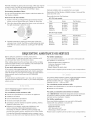
Range HoodCare
The range hood uses 12-volt 20-watt halogen lamps. Before you
begin, make sure that the range hood is turned off and that the
other lamps have had sufficient time to cool.
Replace lamp using a tissue to handle the Iamp or wear cotton
gloves. Do not touch the lamp with bare fingers,
If new lights do not operate, make sure the lamps are inserted
correctly before calling service.
To Replace:
1, Disconnect power,
2, Turn light switch to off.
3, Gently pull the lamp from the socket clips.
4, Insert the new Iamp into the socket clips and gently push the
lamp until firmly in place.
5, Reconnect power
If all the lights do not light when the light switch is turned on,
check that the fuse is good,
1, Disconnect power at the circuit breaker of fused circuit box.
t0
A. Fusecover
B.Fuse
C.Fuseholder
5, Push down and twist to remove the fuse cover.
6, Replace the fuse with a new 5 amp time-delay fuse.
7, Replace the fuse cover.
8, Replace the fuse holder assembly cover with the 2 screws
removed earlier,
9, Reconnect power at the circuit breaker of fused circuit box.
Exterior surfaces:
Do not use steel wool or soap-filled scouring pads. Rub in
direction of the grain Iine to avoid scratching the surface.
Always wipe dry to avoid water marks.
[] KitchenAid '_Professional Formula Stainless Steel Cleaner &
Polish is the cleaner recommended for cleaning stainless steel
surfaces on this product. To order call our Customer Service
Center at 1-800-442-9991 or order on-Iine at
www.applianceaccessories.com and ask for part number
4396920. To order from Canada, call 1-800-807-6777
[] Mild liquid detergent and water.
[] Wipe with damp soft cloth or nonabrasive sponge, then rinse
with clean water and wipe dry.
Meta_ FHters
Use 2 hands to remove filters. Push tab back to release locking
pin, pull down and forward. Repeat with other fiIteK
\\
Wash metal filters as needed in dishwasher or hot detergent
solution to clean.

Reinstallmetalfilterbyplacingthebackedgeoffilterintochannel
atrearofhood.Pushfilterupwhilepushingtabback.Whenfilter
isinplace,releasetab.Lockingpinwillholdfilterinplace.
RecircumatingInstallationFimters:
Donotwashcharcoalfilterpacks.ReplacewithRecirculationKit
PartNumber4396565.
Removetheoldcharcoalfilter:
1. Rotatetotheleft(counterclockwise)andpullawayfromthe
blowercoveranddiscardfilterpack.Repeatforotherfilter.
2. Placethecharcoalfilteragainstthebiowercoverandrotateto
theright(clockwise)toattachtocover.
A ..............
3.
A,Filter
Reinstarl metal filter by placing the back edge of filter into
channel at rear of hood. Push filter up while pushing tab back.
When filter is in place, release tab. Locking pin will hold filter
in place.
Optional installation kits are available from your dealer.
Recirculation Kit Part Number 4396565 includes 2 charcoal filter
packs and vent cover.
Removable front trim Part Numbers:
30" (76.2 era) models
Color Series Part Number
White Architect '_ 8212462
Black Architect ® 8212463
Biscuit Architect ® 8212461
Stainless Pro Line® 8212464
Meteorite Pro Line® 8212465
36" (91.4 cm) models
Color Series Part Number
White Architect _ 8212467
Black Architect '_' 8212468
Biscuit Architect _' 8212466
Stainiess Pro Lind °_ 8212469
Meteorite Pro Lind °_ 8212470
REQUESTINGASSISTANCEORSERVICE
Before calling for assistance or service, please check
"Troubleshooting." It may save you the cost of a service call. If
you still need help, follow the instructions below.
When calling, please know the purchase date and the complete
model and serial number of your appliance. This information will
help us to better respond to your request.
if you _eed replacement parts
If you need to order replacement parts, we recommend that you
use only factory specified replacement parts. Factory specified
parts wH!fit right and work right because they are made with the
same precision used to build ever}, new KITCHENAID@
appliance.
To locate factory specified parts in your area, call our Customer
eXperience Center telephone number or your nearest designated
service center
Catl the KJtchenAid Customer experience Center
toll free: 1-800=422=t230.
Our consultants provide assistance with:
Features and specifications on our full line of appliances
Installation information
Use and maintenance procedures
Accessory and repair parts sales
Specialized customer assistance (Spanish speaking, hearing
impaired, limited vision, etc.)
Referrals to local dealers, repair parts distributors, and
service companies. KitchenAid designated service
technicians are trained to fulfill the product warranty and
provide after-warranty service, anywhere in the United States.
To locate the KitchenAid designated service company in your
area, you can also look in your telephone directory Yellow Pages.
For further assistance
If you need further assistance, you can write to KitchenAid with
any questions or concerns at:
KitchenAid Brand Home Appliances
Customer eXperience Center
553 Benson Road
Benton Harbor, MI 49022-2692
Please include a daytime phone number in your correspondence.
For product related questions, please call the KitchenAid Canada
Customer Interaction Centre tol! free: 1=800=461-5681
Monday to Friday 8:00 a.m. - 6:00 p.m. (EST/.
Saturday 8:30 a.m. - 4:30 p.m. (EST).
Our consultants provide assistance with:
Features and specifications on our full line of appliances.
Referrals to local dealers.
For parts, accessories and service in Canada
Call 1=800=807=6777. KitchenAid designated service technicians
are trained to fulfill the product warranty and provide after-
warranty service, anywhere in Canada.
For further assistance
If you need further assistance, you can write to KitchenAid
Canada with any questions or concerns at:
Customer Interaction Centre
KitchenAid Canada
1901 Minnesota Court
Mississauga, Ontario L5N 3A7
Please include a daytime phone number in your correspondence.
11

KITCHENAID ®VENTILATION WARRANTY
ONE YEAR LIMITED WARRANTY
For one year from the date of purchase, when this major appliance is operated and maintained according to instructions attached to or
furnished with the product, KitchenAid or KitchenAid Canada (hereafter KitchenAid") will pay for factory specified parts and repair
labor to correct defects in materials or workmanship. Service must be provided by a KitchenAid designated service company.
ITEMS KITCHENAID WILL NOT PAY FOR
1. Service calls to correct the installation of your major appliance, to instruct you how to use your major appliance, to replaceor repair
house fuses or to correct house wiring or plumbing.
2. Service calls to repair or replace appliance light bulbs, air filters or water filters. Those consumable parts are excluded from warranty
coverage.
3. Repairs when your major appliance is used for other than normal, single-family household use.
4. Damage resulting from accident, alteration, misuse, abuse, fire, flood, acts of God, improper installation, installation not in
accordance with electrical or plumbing codes, or use of products not approved by KitchenAid.
5. Replacement parts or repair labor costs for units operated outside the United States or Canada.
6. Pickup and delivery. This major appliance is designed to be repaired in the home.
7. Repairs to parts or systems resulting from unauthorized modifications made to the appliance.
8. Expenses for travel and transportation for product service in remote locations.
9. The removal and reinstallation of your appliance if it is installed in an inaccessible location or is not installed in accordance with
published installation instructions.
DISCLAIMER OF IMPLIED WARRANTIES; LIMITATION OF REMEDIES
CUSTOMER'S SOLE AND EXCLUSIVE REMEDY UNDER THIS LIMITED WARRANTY SHALL BE PRODUCT REPAIR AS PROVIDED
HEREIN. IMPLIED WARRANTIES, INCLUDING WARRANTIES OF MERCHANTABILITY OR FITNESS FOR A PARTICULAR PURPOSE,
ARE LIMITED TO ONE YEAR OR THE SHORTEST PERIOD ALLOWED BY LAW. KITCHENAID SHALL NOT BE LIABLE FOR
INCIDENTAL OR CONSEQUENTIAL DAMAGES. SOME STATES AND PROVINCES DO NOT ALLOW THE EXCLUSION OR LIMITATION
OF INCIDENTAL OR CONSEQUENTIAL DAMAGES, OR LIMITATIONS ON THE DURATION OF IMPLIED WARRANTIES OF
MERCHANTABILITY OR FITNESS, SO THESE EXCLUSIONS OR LIMITATIONS MAY NOT APPLY TO YOU. THIS WARRANTY GIVES
YOU SPECIFIC LEGAL RIGHTS AND YOU MAY ALSO HAVE OTHER RIGHTS, WHICH VARY FROM STATE TO STATE OR PROVINCE
TO PROVINCE.
Outside the 50 United States and Canada, this warranty does not apply. Contact your authorized KitchenAid dealer to determine if
another warranty applies.
If you need service, first see the "Troubleshooting" section of the Use & Care Guide. After checking "Troubleshooting," additional help
can be found by checking the "Assistance or Service" section or by calling KitchenAid. In the U.S.A., call 1-800-422-1230. In Canada,
call 1-800-807-6777. 10/05
Keep this book and your samesstip together for future
reference. You must provide proof of purchase or installation
date for in-warranty service.
Write down the following information about your appliance to
better help you obtain assistance or service if you ever need it=
You will need to know your complete modeI number and serial
number. You can find this information on the model and serial
number labeVplate, located on your appliance=
Dealer name
Address
Phone number
ModeB number
Serial number
Purchase date
t2

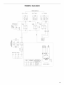
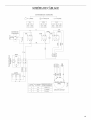
WIRINGDIAGRAM
Sfide Switches
_,_--0-1UGHT _ 0-1 MOT. 12 3 SPEED
WRIN2_OXl
Y-G%
W I O
I
t
GY
cc W
LtJ
CECO
2_
0C
t-
BK
DIRECTIONAL LAMPS
BK OR
SLM
2 4
1 3
W
MOTOR CONNECTIONS OHM RESISTANCE
SPEED rO TERMINALS BETWEEN TERMINALS (_+))
(SEE CONNECTIONS)
1 1+4 15.8_+1.1
2 2-4 11.0_+0.8
3 3+4 5.7_+0.4
MOTOR GROUP
+
13

_ ;_ _
SI CURITI DELAHOTTEDECUISINII RE
Votre s_curit_ et celle des autres est tr_s importante.
Nous donnons de nombreux messages de securite importants dans ce manuel et sur votre appareil menager. Assurez-vous de
toujours lire tous les messages de securite et de vous y conformer.
Voici le symbole d'alerte de securite.
Ce symbole d'alerte de securite vous signale les dangers potentiels de deces et de blessures graves a vous
et a d'autres.
Tous les messages de securite suivront le symbole d'alerte de securite et le mot "DANGER" ou
"AVERTISSEMENT". Ces roots signifient :
Risque possible de deces ou de blessure grave si vous ne
suivez pas immediatement lee instructions.
Risque possible de deces ou de blessure grave si vous
ne euivez pas lee instructions.
Tous les messages de securite vous diront quel est le danger potentiel et vous disent comment reduire le risque de blessure et
ce qui peut se produire en cas de non-respect des instructions.
t4

IIVIPORTANTES iNSTRUCTiONS DE SECURITE
AVERTISSEMENT : POUR REDUIRE LE RISQUE
DqNCENDE, CHOC ELECTRIQUE OU DOMMAGES
CORPORELS, RESPECTER LES INSTRUCTIONS
SUWANTES :
m Utiliser cet appareiI uniquement dans Ies applications
envisag_es par Ie fabricant. Pour toute question, contacter
Jefabricant.
m Avant d'entreprendre un travail d'entretien ou de nettoyage,
interrompre I'alimentation de Ia hotte au niveau du tableau
de disjoncteurs, et verrouiIIer le tableau de disjoncteurs
pour empScher tout retablissement accidentel de
J'alimentation du circuit. Lorsqu'iI n'est pas possible de
verrouiller Ie tableau de disjoncteurs, placer sur le tableau
de disjoncteurs une 6tiquette d'avertissement pro6minente
interdisant Ie retablissement de I'alimentation.
m Tout travail d'installation ou c&biage eIectrique doit _tre
realis6 par une personne qualifi_.e, darts Ie respect des
prescriptions de tous Ies codes et normes applicabIes, y
compris les codes du b&timent et de protection contre les
incendies.
m Une source d'air de debit suffisant est necessaire pour le
fonctionnement correct de tout appareii a gaz (combustion
et _vacuation des gaz a combustion par la chemin_e), pour
qu'iI n'y ait pas de reflux des gaz de combustion. Respecter
Jesdirectives du fabricant de I'equipement de chauffage et
Jesprescriptions des normes de securite - comme celles
publi6es par Ia Nationat Fire Protection Association (NFPA)
et I'American Society for Heating, Refrigeration and Air
Conditioning Engineers (ASHRAE), et les prescriptions des
autorites reglementaires locales.
m Lots d'operations de decoupage et de pergage dans un mur
ou un plafond, veilIer & ne pas endommager les c&blages
electriques ou canaIisations qui peuvent s'y trouver.
m Les systemes d'6vacuation doivent toujours decharger I'air
I'exterieur.
MISE EN GARDE : Cet appareil est conqu uniquement
pour la ventilation gen6raie. Ne pas I'utiliser pour I'extraction
de matieres ou vapeurs dangereuses ou explosives.
MtSE EN GARDE : Pour minimiser le risque d'incendie
et 6vacuer adequatement les gaz, veiller b.acheminer I'air
aspir6 par un conduit jusqu'a I'exterieur - ne pas decharger
J'airaspire dans un espace vide du b&timent comme une
cavite murale, un pJafond, un grenier, un vide sanitaire ou
un garage.
AVERTmSSEMENT : POUR RCDUIRE LE RISQUE
D'INCENDE, UTILISER UNIQUEMENT DES CONDUITS
AVERTISSEMENT : POUR MINIMISER LE RISQUE
D'UN FEU DE GRAISSE SUR LA CUISINIERE :
m Ne iamais laisser un el6ment de surface fonctionner &
puissance de chauffage maximale sans surveillance. Un
renversemenb/debordement de matiere graisseuse pourrait
provoquer une inflammation et Ia gen6ration de fumee.
Utiliser une puissance de chauffage moyenne ou basse
pour le chauffage d'huile.
m VeilIer a toujours faire fonctionner Ie ventitateur de la hotte
Jors de la cuisson avec une puissance de chauffage eIev6e
ou lots de Ia cuisson d'un mets a fiamber (a savoir crSpes
Suzette, cerise iubilee, steak au poivre fiambe).
m Nettoyer fr_quemment les ventiIateurs d'extraction. VeiIIer
ne pas laisser la graisse s'accumuler sur les surfaces du
ventiJateur ou des filtres.
m Utiliser toujours un ustensile de tailIe appropriee. Utiliser
toujours un ustensile adapte a la taille de J'_lement
chauffant.
AVERTISSEMENT: POUR REDUIRE LE RISQUE DE
DOMMAGES CORPORELS APRES LE DECLENCHEMENT
D'UN FEU DE GRAISSE SUR LA CUISINIERE, APPLIQUER
LES RECOMMANDATIONS SUWANTES :4
m Placer sur le recipient un couvercie bien ajuste, une t61e&
biscuits ou un plateau m6tallique POUR ETOUFFER LES
FLAMMES, p.uis eteindre le brOleur b.gaz ou etectrique.
VEILLER A EVITER LES BRULURES. Si Ies fiammes ne
s'eteignent pas imm6diatement, EVACUER LA PIECE ET
APPELER LES POMPIERS.
m NE JAMAIS PRENDRE EN MANNUN RECIPIENT
ENFLAMME - vous risquez de vous brOter.
m NE PAS UTILISER D'EAU, ni un torchon humide - ceci
pourrait provoquer une explosion de vapeur brOlante.
m Utiliser un extincteur SEULEMENT si :
- IIs'agit d'un extincteur de classe ABC, dont on connait le
fonctionnement.
- IIs'agit d'un petit feu encore limite b.I'endroit oQ il s'est
declar&
- Les pompiers ont et_ contact,s.
- IIest possible de garder Ie dos oriente vers une sortie
pendant I'operation de Iutte contre Ie feu.
_Recommandations tirees des conseils de securite en cas
d'incendie de cuisine publies par Ia NFPA.
m AVERTISSE_ENT : Pour reduire Ie risque d'incendie
ou de choc electrique, ne pas utiliser ce ventilateur avec un
queiconque dispositif de reglage de la vitesse a semi-
conducteurs.
CONSERVEZ CES INSTRUCTIONS
15

EXXGENCESD'INSTALLATION
Rassembbr bs outils et pi_ces necessaires avant de commencer
I'instailation. Lire et respecter bs instructions d'installation
foumies avec chacun des outib de cette liste.
Outillage n_cessaire
Niveau
Perceuse
Foret de 11/4"
Crayon
Pince
Pince a denuder ou couteau utilitaire
M_tre-ruban ou r_gle
PistoIet & calfeutrage et compose de caifeutrage resistant aux
intemperies
Scie sauteuse ou scie a guichet
Ruban adhesif pour conduit
Toumevis a lame plate
Cisaille de ferblantier
Toumevis Phillips
Toume-ecrou ou douille de 7 mm
Pi_ces fournies
Verifier que toutes les pi_ces sont presentes.
4 vis
4 chevilles
Clapet anti-reflux
Pi_ces n6cessaires
Serre=c_bb de 1/2"(12,5 mm) (homologation UL ou CSA) (2)
Cable d'alimentation ebctrique
Bouche de decharge murale ou sur toit de 6" (15,2 cm)
Circuit d'evacuation metallique de dia=6" (15,2 cm)
iMPORTANT : Observer bs dispositions de tousles codes et
r_gbments en vigueuK
[] C'est _ I'installateur qu'incombe la responsabilite de respecter
bs distances de separation exig@es,specifi@es sur Ia plaque
signatetique de I'appareiL La plaque signal&tique est situee
I'interieur de Ia hotte, sur Ia paroi arri@re.
[] Installer Ia hotte de cuisini&re a distance de toute zone
exposee a des courants d'air, comme fen@tres, portes et
bouches de chauffage.
[] Respecter Ies dimensions indiqu@es pour Ia cavit_
d'installation entre Ies placards. Les dimensions indiqu_es
prennent en compte Ies valeurs minimales des degagements
de separation necessaires. Avant d'effectuer des decoupages,
consulter les instructions d'installation foumies par le fabricant
de Ia table de cuisson/cuisini_re.
[] On doit disposer d'une prise de courant electrique reliee a la
terre. Voir Ia section "Specifications elecMques'.
[] La hotte a et_ configuree a I'usine pour une instailation avec
decharge a !'exterieur. Pour une installation avec recyclage,
utiliser I'ensemble de recyclage (piece n° 4396565) qui
contient un cache-conduit et 2 filtres a charbon (disponible
chez Ies revendeurs).
[] Assurer I'&tancheite au niveau de chaque ouverture decoupee
dans le plafond ou lemur pour I'installation de la hotte de
cuisiniere.
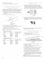
Dimensions du produit
collerette pour d@harge
de dia. 5_/_'' (14,9 crn)
2OSY_6. (76,0 cm) - rnod_le de 30" (76,2 cm)
(51,3 crn)._ _35_5/16 '' (91,3 cm) - modele de 36" (91,4 cm)
Emplacement des vis de montage et des ouvertures pour
c_Mes _tectriques et conduits d'_vacuation
axe central de la
57Xs' collerette 9Xs"
(14,9 cm) cm)
1¼" 13/16.
(3,2cm) (3,0cm)
(10,0 cm)
axe vertical
de la hotte
arrachabbs (19,0cm)
t6

D_gagements de s_paration _ respecter
largeur de I'ouverture
X du placard
30"(76,2cm)ou
',¢_;-36"(91,4 cm) rain.
distance sugg6r6e du
bas de la hotte & la
surface de cuisson
24" (61,0 cm) rain.
30" (76,2 cm)
70%6"
(178,6 cm)
rain. at
distance entre 765Ad,
le placard (193,8 cm)
mural et le plan u'au
de travail 18" bas du cadre
(45,7 cm) rain. de placard
Hauteur du
placard de
la base
36" (91,4 cm)
[] Utiliser autant que possible des sections droites et minimiser
le nombre de coudes.
[] Ne pas terminer Ie conduit d'evacuation dans un grenier ou
dans un autre espace ferme.
[] Ne pas utiliser une bouche de d6charge murale de 4" (10,2 cm)
normalement utilisee pour un equipement de buanderie.
[] Le syst_me doit decharger I'air a I'ext6rieur.
[] Utiliser uniquement du conduit m6tailique de 6" (15,2 cm). Un
conduit en metal rigide est recommande. Ne pas utiliser un
conduit de plastique ou en m_tal mince.
[] La taille du conduit dolt 6tre uniforme.
[] Le syst6me d'6vacuation dolt comporter un clapet. Si la
bouche de decharge murale ou par Ie toit comporte un
ctapet, ne pas utiliser le clapet fourni avec la hotte de
cuisini_re.
[] Au niveau de chaque jointure du conduit de decharge,
assurer 1'6tanch{_it6avec du ruban adhesif pour conduit.
[] Autour de la bouche de d6charge a I'exterieur, assurer
I'etancheite avec un produit de calfeutrage.
[] D_terminer quelle methode d'evacuation est la plus
appropriee.
Pour obtenir Bameilleure performance
[] Ne pas installer 2 coudes ensemble.
[] Ne pas utiliser plus de trois coudes a 90 °.
[] Si un coude est utilise, on doit Ie placer le plus loin possible
de I'ouverture de sortie du ventilateur.
[] Veiller a incorporer une section de conduit rectiligne d'au
moins 24" (61 cm) entre deux raccords coudes adjacents.
[] La Iongueur du syst_me d'6vacuation et Ie nombre de coudes
dolt &tre r6duit au minimum pour fournir la meilleure
performance.
Installations pour regions a climat ftoid
On devrait insta!ler un clapet antirefiux additionneI pour minimiser
le reflux d'air froid, et incorporer un element non metallique
d'isolation thermique pour minimiser la conduction de chaleur par
I'interm_diaire du conduit d'evacuation, de I'interieur de la maison
I'exterieur. Le clapet anti-reflux dolt _tre place du c6te air froid
par rapport a I'element d'isolation thermique.
Air d"appoint
Le code du bgtiment local peut exiger I'emploi d'un systeme
d'appoint d'air lots de I'emploi d'un ventilateur d'extraction dont
la capacite d'aspiration est superieure a un debit (pieds cubes
par minute) specifie. Le debit specifie, pieds cubes par minute,
est variable d'une juridiction a une autre. Consulter un
professionneI des installations de chauffage ventilation/
climatisation au sujet des exigences specifiques applicables
dans la juddiction locale.
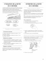
Methodes d'_vacuation
La hotte de cuisini6re a ete configuree a I'usine pour I'installation
avec decharge a I'ext6rieur. La decharge de I'air aspir6 peut 6tre
effectuee atravers Ie mur ou Ie toil On dolt utiliser un circuit
d'evacuation de dia. 6" (!5,2 cm). La Iongueur effective du circuit
d'evacuation ne dolt pas depasser 35 pi (10,7 m).
Option 1 - D_charge
travers le toit
B
Option 2 -
D_charge
travers le tour
A_ ] c
Option 3 - D_charge
travers le tour
avec _vacuation par
_"arri_re
A, ¸¸
A. Conduit de dia. 6" (15,2 cm)
B, Bouche de decharge sur le to/t
C. Bouche de decharge murale
Le raccord de sortie peut aussi 6tre orient_ de fagon & aspirer I'air
l'arri_re de la hotte.
i7

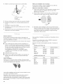
Ca_culde_a_ong_e_reffective d_ circuit
d'_vac_ation
Pour calculer la Iongueur effective du circuit d'evacuation
necessaire, additionner les Iongueurs _quivatentes (pieds/m_tres)
de tousles composants utilises darts le syst6me.
Oomposant Conduit et raccords alia. 6" (15,2 cm)
Coude 9.45° 2,5 pi (0,8 m)
Coude b,90° 5,0 pi (1,5 m)
Exemple de syst_me de d_charge
Coude _ 90° L_----- 6 pi (1,8 p/I)_ Bouche de
I
/. d_charge murale
\
2 pi
(0,6rn)
Longueur maximum = 35 pi (10,7 m)
1 coude a 90 ° = 5 pi (1,5 m)
section droite de 8 pi (2,4 m) = 8 pi (2,4 m)
1 bouche de decharge murale = 0 pi (0 m)
Longueur equivalente totale
du systeme = 13 pi (3,9 m)
NOTE : On d_conseille I'emploi d'un conduit flexible. Un conduit
flexible peut susciter une r&tro-pression et des turbulences de
I'air, ce qui r6duit consid_rablement la pedormance.
IMPORTANT : Observer les dispositions de tous Ies codes et
r_glements en vigueur. Conserver Ies instructions d'installation
pour consultation par I'inspecteur des installations electriques.
C'est au client qu'incombe Ia responsabilite de contacter un
electricien qualifie et de veiller ace que I'installation electrique
soit adequate et r_alisee en conformite avec Ies prescriptions de
la plus r_cente edition de Ia norme National Electrical Code,
ANSI/NFPA 70, ou de Ia norme CSA C22.1-94, Code canadien de
I'electricit6, partie 1 et C22.2 N° 0-M91, et de tousles codes et
r_glements Iocaux en vigueur.
Si Ies codes le permettent et si on utilise un conducteur distinct
de liaison a Ia terre, il est recommande qu'un electricien qualifie
verifie la qualite de la liaison a Iaterre.
Pour obtenir un exemplaire de la norme des codes ci-dessus,
contacter :
National Fire Protection Association
One Batterymarch Park, Quincy, MA 02269
CSA International
8501 East Pleasant Valley
Road Cleveland, OH 44131-5575
L'appareil doit 6tre alimente par un circuit de 120 V, 60 Hz, CA
seulement, 15 amperes, protege par fusible.
Ne pas utiliser une tuyauterie de gaz pour le raccordement
la terre.
En cas de doute quanta Ia qualite de la liaison a Ia terre de la
hotte de la cuisini_re, consulter un electricien qualifi&
Ne pas installer un fusible dans Ie conducteur neutre ou Ie
conducteur de liaison a la terre.
La hotte doit _tre raccordee au reseau electrique uniquement
avec des conducteurs de cuivre.
La hotte doit _tre raccord6e directement au coupe-circuit
avec fusible ou au disioncteur par I'interm_diaire de c&ble &
conducteurs de cuivre, a blindage metallique flexible ou
gaine non-metallique.
Le calibre des conducteurs (cuivre seulement) et les
connexions doivent &tre compatibles avec la demande de
courant de I'appareiI specifi6e sur la plaque signaletique.
Le calibre des conducteurs doit satisfaire les exigences de la
plus recente edition de la norme National Electrical Code,
ANSI/NFPA 70, ou de la norme CSA C22.1-94, Code
canadien de electricit6, pattie 1 et C22.2 N° 0-M91 et de tous
les codes et r6glements en vigueur.
Un serre-c&ble de IA" (12,7 mm) (homologation UL ou CSA)
dolt &tre installe a chaque extremite du c&bte d'atimentation
(sur la hotte et sur le bokier de distribution).
t8

INSTRUCTIONSD'INSTALLATION
Instructions g_n@ates
lnstaJJation avec d_charge _ m"ext_deur :
Ex6cuter Ies decoupages necessaires darts Ie mur pour le
passage des conduits.
NOTE : La bouche de decharge de Ia hotte peut 6tre odentee
pour evacuer par I'arrJ_re de Ia hotte en 6tant le moteur et en le
faisant pivoter de facon ace que le raccord de sortie soit situe &
Parri@ede Ia hotte. Si cette configuration est d&siree, voir la
section "Modification de Ia hotte pour evacuation par J'arri@e"
pour modifier la direction de Pevacuation.
IMPORTANT : Veiller a installer le circuit d'evacuation avant
d'entreprendre Hnstallation de la hotte.
lnstaJJation avec recyclage :
Un circuit d'evacuation (non foumi) qui decharge Fair aspir6 dans
la piece, & travers Ie soffite ou a travers Ie sommet du placard, est
necessaJre. Utiliser Fensemble de recyclage num@o 4396565.
Pour Finformation de commande, voir "Assistance ou service".
IMPORTANT : Dans Ie cas de Ia decharge de Fair & travers Ie
sommet du placard, veifler a ne pas terminer Ie conduit de
decharge dans un espace ferme comme un grenier ou une cavite
fermee sous le soffite.
Dans Ie cas de la decharge de Fair & travers le soffite, placer Ie
circuit d'evacuatJon (non fourni) & utilJser sur Jeraccord de sortie,
maJs sans dej& le fixer.
NOTE : On peut ptacer Ie conduit d'6vacuation de tefle mani_re
qu'il decharge Fair aspir& par Favant du soffJte, ou par Fune des
extremites Jat@Nes du soffite.
D_charge _ travers Je soffite
1. Sur une surface plane recouverte d'un mat@iau de protection,
assembler le syst6me d'evacuation (non foumi) a utiliser sur le
raccord de sortie mais sans deja le fixer.
NOTE : On peut placer le syst6me d'evacuation de te!le
mani6re qu'il decharge Fair aspire par I'avant du soffite. On
peut egaJement le reorienter de fagon & ce que I'evacuation
s'effectue sur le c6te ou & l'extremite du soffite.
2. Retever Ia dimension "A" (entre Ie sommet de Ia hotte et !'axe
central du conduit de diametre 6" [15,2 cm]). Reporter la
distance "A" sur le soffite.
D6charge _ travers Je sommet du placard
Marquer I'emplacement oQ Ia grille de sortie sera installee au
sommet du placard; et decouper une ouverture de dia.
6"(15,2 cm) pour Ia grille de sortie.
IMPORTANT : Ne pas terminer le conduit de d&charge dans
un espace ferme comme un grenier ou une cavJte fermee
sous le soffJte.
C
.............. J %%%
.......... ,,,,, E
A. Circuit d'evacuation
B. E,s_placementde/a
grille de sortie
C. Sommet du placard
D. Plafond ou soffite
E. Hotte
[] Instaflations avec decharge & I'ext@ieur : on recommande
d'instNler Ie circuit d'evacuation avant d'entreprendre
J'JnstaHationde Ia hotte.
[] On ne dolt couper un poteau de colombage ou une soJive
que si c'est absolument necessaire. S'iI est n_cessaire de
couper un poteau ou une soJive, on devra construire une
structure de support appropriee.
[] Avant d'ex6cuter les decoupages, v@ifier Ia disponibilit_ d'un
espace de passage suffisant darts le plafond ou Iemur pour
Jeconduit d'evacuation.
[] Vedfier que toutes les pieces et la bo_te contenant les filtres
ont ete retirees de I'embNlage.
Preparation
Risque du poids excessif
UtiHser deux ou plus de personnes pour deNacer et
installer _acuisiniereo
Le non-respect de cette instruction peut causer
une bJessure au dos ou d"autre Nessure.
1. Si possible, deconnecter Ia cuisini@e des circuits d'eJectricite
et/ou de gaz et deplacer la cuisiniere autonome ou encastree
hors de son espace d'installation entre les placards pour
faciliter I'acc_s au mur arri_re.
2. Selectionner une surface plane pour Fassemblage de la
hotte. Lors de Fassemblage, recouvrir cette surface avec un
mat@iau de protection - couverture ou feuHle de carton.
3. Relever Ies dimensions appropdees et decouper une
ouverture de dia. 6" (15,2 cm).
19

3,
4,
5,
6,
7,
8,
Risque du poids excessif
Utiliser deu× ou plus de personnes pour deplacer et
installer la hotte de la cuisiniereo
Le non-respect de cette instruction peut causer
une blessure au dos eu d'autre blessure.
Faire intervenir 2 personnes ou plus pour soulever la hotte
pour la placer sur la surface protegee.
Faire reposer Ia hotte sur sa face arri6re, et enlever Ies filtres
metatliques. Pousser Ia languette vers I'arri6re pour degager la
broche de verrouillage, et tirer vers le bas/vers I'avant.
R6peter ceci pour cheque filtre.
Retirer Ie paquet de pi6ces de quincaillerie.
Ajouter des tringles d'appui en bois selon Ie besoin, sur Ie
fond du placard. Percer des avant-trous de 4s/16"(4,8 mm)
pour les vis de montage de Ia hotte.
13¾" (349 cm) = modele de 30" (76,2 cm)
module de 36" (91,4 cm)
I
/
(seulement pour un tour trous de 1:_A¢
placardmuralavec :_A6"(4,8 ram) (4,8cm)
fonden retrait)
Percer un trou de diam6tre de 61/," (16,5 cm) dens Ie fond du
placard -voir I'ilJustration.
NOTE : En cas de modification de la hotte pour evacuation
par I'arri6re, omettre cette etape. Voir Ia section "Modification
de Ia hotte pour evacuation par I'arri6re" pour modifier la
direction de I'evacuation.
trou dia. 61/2' (16,5cm) ! ..axecentral
!/
tour 3I5/w'
(10,0cm)
Percer un trou de 11/4" (3,2 cm) pour le passage du cSble
d'alimentation.
surface de montage(placard
mural ou soffite) u
9, Placer Ie cSble d'alimentation a travers le trou conform&merit
aux prescriptions des normes et codes en vigueur - National
Electrical Code ou normes CSA, codes et r_glements Iocaux.
IIfaut que la Iongueur du c_ble d'alimentation soit suffisante
entre le cSble de distribution et Ia hotte pour qu'il soit facile
de realiser les raccordements dens le bokier de connexion de
Ia hotte.
10, Utiliser un calfeutrant pour assurer I'etancheite au niveau de
chaque ouverture decoupee.
IMPORTANT : Ne pas mettre le syst_me sous tension event
d'avoir compl_tement termine I'installation.
", { : t:
c
La hotte sort de I'usine avec Ie raccord de sortie sur Ia partie
superieure de Ia hotte. La bouche de d6charge de Ia hotte peut
6tre orientee pour evacuer par I'arriere a travers Ie raccord de
sortie. Pour une evacuation par I'arri6re de la hotte, suivre la
proc6dure qui suit.
1, A partir de I'int&rieur de la hotte, 6ter la vis retenant Ie
conducteur de liaison a Ia terre au moteur du ventilateuL
2,
3,
B C
A. Moteurduventflateur
B.Visdu conducteurdeliaisonb /aterre
C.Prisedu moteurduventflateur
D.Attachederetenue
Debrancher Ie conducteur fixe au moteur du ventilateur.
Oter Ie conducteur du moteur du ventilateur et Ie conducteur
de liaison a Ia terre de I'attache de retenue sur Ia hotte.
Retourner la hotte et retirer les vis fixant le ventilateur a la
hotte.
A. Moteur du ventflateur
B. Vis
2O
I
axe central ....... I
I
troudepassagedu
caned'alimentation
&traversletour
La page est en cours de chargement...
La page est en cours de chargement...
La page est en cours de chargement...
La page est en cours de chargement...
La page est en cours de chargement...
La page est en cours de chargement...
La page est en cours de chargement...
La page est en cours de chargement...
-
 1
1
-
 2
2
-
 3
3
-
 4
4
-
 5
5
-
 6
6
-
 7
7
-
 8
8
-
 9
9
-
 10
10
-
 11
11
-
 12
12
-
 13
13
-
 14
14
-
 15
15
-
 16
16
-
 17
17
-
 18
18
-
 19
19
-
 20
20
-
 21
21
-
 22
22
-
 23
23
-
 24
24
-
 25
25
-
 26
26
-
 27
27
-
 28
28


KitchenAid KHTU705RSS1 Le manuel du propriétaire
- Catégorie
- Hottes
- Taper
- Le manuel du propriétaire
- Ce manuel convient également à
