Maytag MAH22PDAWW0 Installation Instructions Manual
- Catégorie
- Machines à laver
- Taper
- Installation Instructions Manual
Ce manuel convient également à

FClAYI'AG®
COMMERCIAL AUTOMATIC SHER
INSTALLATION AND SETUP INSTRUCTIONS
LAVEUSE AUTOMATIQU E
GUIDE D'UTILISATION ET D'ENTRETIEN
FOR QUESTIONS ABOUT FEATURES, OPERAI-ION/PERFORMANCE, PARTS, ACCESSORIES OR SERVICE
CAI.I.: 1.800.688.9900
IN CANADA, CAI.I.: 1.800.807.6777
VISIT OUR WEBSITE AI-
WWW. MAYTAGCOMMERCIAI .I.AU N D RY.COM
AU CANADA, POUR DES QUESTIONS ,_ PROPOS DES CARACTERISTIQUES,
DU FONCTIONNEMENT/RENDEMENI, DES PIECES, DES ACCESSOIRES OU DU SERVICE,
COMPOSEZ I.E : 1.800.807.6777
OU VISITEZ NOTRE SITE INTERNET ,_
WWW. MAYTAGCOMM ERCI AI .I.AU N D RY.COM
PARA OBTENER ACCESO AI. MANUAl. DE USO Y CUIDADO EN ESPAIqOI., O PARA OBTENER INFORMACION ADICIONAI. ACERCA DE SU PRODUCTO, VISITE: WWW.MAYTAG.COM.
TENGA I.ISTO SU N_JMERO DE MODEI.O COMPI.ETO. PODRA ENCONTRAR El. N_JMERO DE MODEI.O Y DE SERIE EN I.A ETIQUETA UBICADA DEBAJO DE I.A TAPA DE I.A I.AVADORA.
W10165327A

iliiiiiiiiiiiiiiiiiiiiiiiiiiilil!i!i!i!i!i!i!i!iiiiiiiiiiiiiiiiiiiiiiiiiiiiiiiiiiiiiiiiiiiiiiiiiiiiii!iiiiii//liliiii_iiii_iiii_iiii_iiii_iiii_iiii_iiii_iiii_iiii_iiii_iiii_iiiiii_iiiiii_iiiiiIi_iiiiiiiiiiiiliiii_iiiiiiiii_iiiiiiiii_iiiiiiiii_iiiiiiiiiiiiiiiiiiiilIiiiiiiiiiilliiiiiiiiiiiiii!!iiiil¸¸_iiiiiii_iii_ii_.....................................................................ii_iiiiiiiiiiiiiiiiiiiii_iiiiiiiiiiliiiiiiiiiiiiliiiiiiiiiiiIiiiiiiiiiiii_i_iiiii_iiiiiiiiiiiiiiiiiiiiiiiiiiiiiiiiiiiliiiiiiiiiiiliiiiiiiiiiiliiiiiiiiiiiiiiiiiiiiiiiiiiiiiiiiiiiiiiiiiiiiiiiiiiiiiiiiiiiiiiiiiiiiiiiiiii
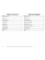
TABLE OF CONTENTS
WASHER SAFETY .................................................................................................................... 3
INSTALLATION REQUIREMENTS ........................................................................................... 4
Tools and Parts ..................................................................................................................... 4
Options ................................................................................................................................ 5
I.ocation Requirements ......................................................................................................... 6
Drain System ........................................................................................................................ 7
Electrical Requirements ........................................................................................................ 7
INSTALLATION INSTRUCTIONS ........................................................................................... 8
Remove Transport System .................................................................................................... 8
Connect the Inlet Hoses ....................................................................................................... 9
Route the Drain Hose ......................................................................................................... 10
Secure the Drain Hose ....................................................................................................... 10
I_eve[ the Washer ................................................................................................................ 11
Complete Installation ......................................................................................................... 11
SETUP INSTRUCTIONS ........................................................................................................ 12
General User Information ................................................................................................... 12
Control Setup Procedures ................................................................................................... 13
Start Operating Setup ......................................................................................................... 13
Washer Diagnostic Mode ................................................................................................... 16
CLEANING YOUR WASHER ................................................................................................. 17
Water Inlet Hoses ............................................................................................................... 18
ASSISTANCE OR SERVICE ..................................................................................................... 18
Accessories ........................................................................................................................ 18
WARRANTY .......................................................................................................................... 19
TABLE DES MATIERES
SI_CURITI_ DE LA LAVEUSE ................................................................................................... 21
EXIGENCES DqNSTALLATION ............................................................................................. 22
Outillage et pi_ces ............................................................................................................. 22
Options .............................................................................................................................. 23
Exigences d'emplacement .................................................................................................. 24
Syst_me de vidange ............................................................................................................ 25
Sp6cifications 6[ectriques ................................................................................................... 25
INSTRUCTIONS DqNSTALLATION ..................................................................................... 26
D6pose du syst_me de transport ......................................................................................... 26
Raccordement des tuyaux d'a[imentation .......................................................................... 27
Acheminement du tuyau de vidange .................................................................................. 28
Immobilisation du tuyau de vidange .................................................................................. 28
R6g[age de ['aplomb de [a [aveuse ..................................................................................... 29
Achever ['installation .......................................................................................................... 29
INSTRUCTIONS DE CONFIGURATION .............................................................................. 30
Information g6n6rale pour ['utilisateur ............................................................................... 30
Proc6dures de r6g[age des syst_mes de commande ........................................................... 31
Param6trage pour mise en marche ..................................................................................... 31
Mode de diagnostic de Ha[aveuse ...................................................................................... 35
NETTOYAGE DE LA LAVEUSE .............................................................................................. 36
Tuyaux d'arriv6e d'eau ....................................................................................................... 37
ASSISTANCE OU SERVICE .................................................................................................... 37
Accessoires ......................................................................................................................... 37
GARANTIE ............................................................................................................................. 38
2

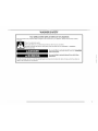
WASHER SAFETY
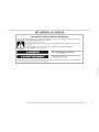
Your safety and the safety of others are very important.
We have provided many important safety messages in this manual and on your appliance. Always read and obey all safety
messages.
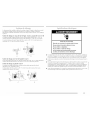
This is the safety alert symbol.
This symbol alerts you to potential hazards that can kill or hurt you and others.
All safety messages will follow the safety alert symbol and either the word "DANGER" or "WARNING."
These words mean:
You can be killed or seriously injured if you don't immediately
follow instructions.
You can be killed or seriously injured if you don't follow
instructions.
All safety messages will tell you what the potential hazard is, tell you how to reduce the chance of injury, and tell you what can
happen if the instructions are not followed.
_ 3

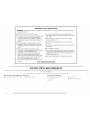
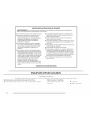
IMPORTANT SAFETY INSTRUCTIONS
WARNING: To reduce the risk of fire, electric shock, or injury to persons when using the washer, follow basic precautions,
including the following:
• Read all instructions before using the washer.
• Do not wash articles that have been previously cleaned
in, washed in, soaked in, or spotted with gasoline,
dry-cleaning solvents, other flammable, or explosive
substances as they give off vapors that could ignite or
explode.
m Do not add gasoline, dry-cleaning solvents, or other
flammable, or explosive substances to the wash water.
These substances give off vapors that could ignite or
explode.
m Under certain conditions, hydrogen gas may be
produced in a hot water system that has not been used
for 2 weeks or more. HYDROGEN GAS IS
EXPLOSIVE. If the hot water system has not been
used for such a period, before using the washing
machine, turn on all hot water faucets and let the water
flow from each for several minutes. This will release
any accumulated hydrogen gas. As the gas is
flammable, do not smoke or use an open flame during
Do not allow children to play on or in the washer. Close
supervision of children is necessary when the washer is used
near children.
Before the washer is removed from service or discarded,
remove the door or lid.
• Do not reach into the washer if the drum, tub or agitator is
moving.
• Do not install or store the washer where it will be exposed to
the weather.
• Do not tamper with controls.
• Do not repair or replace any part of the washer or attempt any
servicing unless specifically recommended in this manual or in
published user-repair instructions that you understand and
have the skills to carry out.
• See "Electrical Requirements" for grounding instructions.
this time.
SAVE THESE INSTRUCTIONS
INSTALLATION REQUIREMENTS
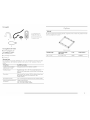
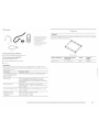
Gather the required tools and parts before starting, installation. The parts supplied are in the washer drum.
Tools needed for connedin 8 the water inlet hoses Tools needed for installation
• Pliers (that open to 1%6" [39..5 mm]) • Flashli_,ht (optional) • Open end wrenches 14 mm •
and 13 mm
• I.evel
Wood block
Ruler or measuring tape
4 .....

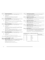
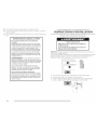
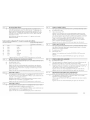
Parts supplied
A B
E
C
D
A. U-shaped hose form
B. Water inlet hoses (2)
C. Inlet hose washers (4)
D. 7}ansit bolt hole plug (4)
E. Beaded tie strap
Parts supplied for PD Models:
• Service door lock cam
Parts supplied PR Models:
• Card reader bezel
• Card reader wire harness
• Screws (2)
Alternate Parts
Your installation may require additional parts. If you are interested in purchasing one of the
items listed here, ca[[ the toil-free number on the cover or in the "Assistance or Service"
section.
If You Have You Will Need to Buy
Laundry tub or standpipe Surnp pump system (if not already available)
taller than 96" (2.4 m)
Overhead sewer Standard 20 gal. (76 I.), 30" (76.2 cm) tail drain tub or
utility sink and sump pump (available from local plumbing
suppliers)
Floor drain Siphon break, Part Number 285834; additional drain hose,
Part Number 8318155; and connector kit, Part
Number 285835
Drain hose too short 4 ft (1.2 m) drain hose extension kit, Part Number 285863
Water faucets beyond reach 2 longer water fi[[ hoses:
of fi[[ hoses 6 ft (1.8 m) Part Number 76314
10 ft (3.0 m) Part Number 350008
Pedestal
You have the option of purchasing pedestals, separately for this washer. The pedestal wi[[ add
to the total height of the washer.
Optional pedestal
Pedestal Height Approximate height Color Model Number
with washer
i,_HHHH_
27/8'' (7.3 cm) 47.5" (120.7 cm) White WHP040
_,;iHr,,i

Selecting the proper location for your washer improves performance and minimizes noise and Washer Dimensions
possible washer "walk."
Your washer can be installed under a custom counteb or in a basement, laundry room, closet,
or recessed area. See "Drain System."
Companion appliance location requirements should also be considered. Proper installation is
your responsibility.
You will need
A water heater set to deliver 120°F (49°C) water to the washer.
A grounded e[ectrica[ outlet [ocated within 6 ft (1.8 m) of where the power cord is
attached to the back of the washer. See "Electrical Requirements."
Hot and cold water faucets located within 4 ft (1.2 m) of the hot and cold water fill valves,
and water pressure of 20-100 psi (137.9-689.6 kPa).
A [eve[ f[oor with a maximum s[ope of 1II (2.5 cm) under entire washer. Installing the
washer on soft floor surfaces, such as carpets or surfaces with foam backing, is not
recommended.
• A sturdy and solid f[oor to support the washer with a total weight (water and [oad) of
400 [bs (180 kg).
Do not operate your washer in temperatures below 32°F (0°C). Some water can remain in the
washer and can cause damage in low temperatures.
Installation clearances
• The location must be large enough to allow the washer door to be fully opened.
• Additional spacing should be considered for ease of installation and servicing. The door
opens more than 90 °, and it is not reversible.
• Additional clearances might be required for wall, door, and floor moldings.
• Additional spacing of 1" (2.5 cm) on all sides of the washer is recommended to reduce
noise transfen
/
(
44%"
(113.4cm)
2813/_6''
(73.2 cm)
Door is not reversible.
A floor drain should be provided under the bulkhead. Prefabricated bulkheads with electrical
outlets, water inlet lines and drain facilities should be used only where local codes permit.
• Companion appliance spacing should also be considered.
6

The washer can be installed using the standpipe drain system (floor or wall), the laundry tub
drain system, or the floor drain system. Select the drain hose installation method you need.
See "Tools and Parts."
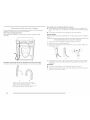
Standpipe drain system - wall or floor (views A & B)
The standpipe drain requires a minimum diameter standpipe of 2" (5 cm). The minimum
carry-away capacity can be no less than 17 gal. (64 I_)per minute.
The top of the standpipe must be at [east 30" (76.2 cm) high and no higher than 96" (2.4 m)
from the bottom of the washer.
T
30"rnin.
(76.2ira)
B
Laundry tub drain system (view C)
The laundry tub needs a minimum 20 gal. (76 I.) capacity. The top of the laundry tub must be
at [east 30" (76.2 cm) above the floor.
Floor drain system (view D)
The floor drain system requires a siphon break that may be purchased separately. See "Tools
and Parts."
The siphon break must be a minimum of 28" (71 cm) from the bottom of the washer.
Additional hoses might be needed.
Electrical Shock Hazard
Plug intoa grounded 3 prong outlet,
Do not remove ground prong,
Do not use an adapter.
Do not use an extension cord.
Failure to follow these instructions can result in death,
fire, or electrical shock.
A 120 volt, 60 Hz., AC only, 15- or 20-amp, fused electrical supply is required. A time-
delay fuse or circuit breaker is recommended. It is recommended that a separate circuit
serving only this appliance be provided.
This washer is equipped with a power supply cord having a 3 prong grounding plug.
To minimize possible shock hazard, the cord must be plugged into a mating, 3 prong,
grounding-type outlet, grounded in accordance with local codes and ordinances. If a
mating outlet is not available, it is the personal responsibility and obligation of the
customer to have the properly grounded outlet installed by a qualified electrician.
If codes permit and a separate ground wire is used, it is recommended that a qualified
electrician determine that the ground path is adequate.
C D

• I)o not ground to a gas pipe.
• Check with a qualified electrician if you are not sure the washer is properly grounded.
• I)o not have a fuse in the neutral or ground circuit.
GROUNDING iNSTRUCTiONS
For a grounded, cord=connected washer:
This washer must be grounded. In the event of a malfunction
or breakdown, grounding will reduce the risk of electrical
shock by providing a path of least resistance for electric
current. This washer is equipped with a cord having an
equipment-grounding conductor and a grounding plug. The
plug must be plugged into an appropriate outlet that is
properly installed and grounded in accordance with all local
codes and ordinances.
WARNING: Improper connection of the equipment-
grounding conductor can result in a risk of electric shock.
Check with a qualified electrician or serviceman if you are in
doubt as to whether the appliance is properly grounded.
Do not modify the plug provided with the appliance - if it will
not fit the outlet, have a proper outlet installed by a qualified
electrician.
For a permanently connected washer:
This washer must be connected to a grounded metal,
permanent wiring system, or an equipment grounding
conductor must be run with the circuit conductors and
connected to the equipment-grounding terminal or lead on
the appliance.
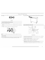
INSTALLATION INSTRUCTIONS
Excessive Weight Hazard
Use two or more people to move and install washer.
Failure to do so can result in back or other injury.
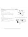
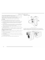
IMPORTANT: Position the washer so that the rear of the washer is within approximately 3 ft
(90 cm) of its final location.
There are 4 blue bolts in the rear panel of the washer that support the suspension system
during transportation. These bolts also retain the power cord inside the washer until the bolts
are removed.
1. Keep the washer in the upright position while removing the blue bolts.
2. Using a 13 mm wrench, loosen each of the bolts.
3. Once the bolt is loose, move it to the center of the hole and completely pull out the bolt,
including the plastic spacer covering the bolt.
4. Once all 4 bolts are removed, discard the bolts and spacers. Then pull the power cord
through the opening of the rear panel and close the hole with the attached cap.
5. Close the bolt holes with the 4 transport bolt hole plugs.
NOTE: If the washer is to be transported at a later date, call your local service center. To avoid
suspension and structural damage, your washer must be properly set up for relocation by a
certified technician.
8 .....

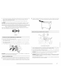
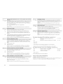
Insert new flat washers (supplied) into each end of the inlet hoses. Firmly seat the washers in
the couplings.
A B
A. Coupling
B.Washer
Connect the inlet hoses to the water faucets
Make sure the washer drum is empty.
1. Attach a hose to the hot water faucet. Screw on coupling by hand until it is seated on the
washer.
2. Attach a hose to the cold water faucet. Screw on coupling by hand until it is seated on the
washer.
3. Using pliers, tighten the couplings with an additional two-thirds turn.
NOTE: Do not overtighten or use tape or sealants on the valve. Damage to the valves can
resu It.
Clear water lines
• Run water through both faucets and inlet hoses, into a laundry tub, drainpipe or bucket,
to get rid of particles in the water lines that might clog the inlet valve screens.
• Check the temperature of the water to make sure that the hot water hose is connected to
the hot water faucet and that the cold water hose is connected to the cold water faucet.
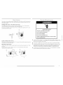
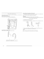
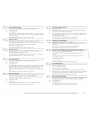
Connect the inlet hoses to the washer
/
H. Hot water inlet
C. d_;M water inlet
1. Attach the hot water hose to the washer's hot (H) water inlet valve. Screw on coupling by
hand until it is seated on the washen
2. Attach the cold water hose to the washer's cold (C) water faucet. Screw on coupling by
hand until it is seated on the washen
3. Using pliers, tighten the couplings with an additional two-thirds turn.
NOTE: Do not overtighten. Damage to the coupling can result.
4. Turn on the water faucets completely and check for leaks.
NOTE: Replace inlet hoses after 5 years of use to reduce the risk of hose failure. Record
hose installation or replacement dates on the hoses for future reference.
Periodically inspect and replace hoses if bulges, kinks, cuts, wea_; or leaks are found.

Properroutingofthedrainhoseprotectsyourfloorfromdamageduetowaterleakage.Read
andfollowtheseinstructions.
Remove drain hose from the washer
Gently pull the corrugated drain hose from the shipping dips.
To keep drain water from going back into the washer:
• I)o not straighten the drain hose, and do not force excess drain hose into standpipe. Hose
should be secure, but loose enough to provide a gap for air.
• Do not lay excess hose on the bottom of the laundry tub.
Floor drain
You may need additional parts. See Floor drain under "Tools and Parts."
1.
2.
3.
Drape the power cord over the washer top.
Move the washer to its final location.
Place the drain hose in the laundry tub or standpipe as shown. See illustrations A and B.
Laundry tub drain or standpipe drain
Connect the drain hose form to the corrugated drain hose.
A B
A. Snap either end of the drain hose form to the drain hose at
the point where the corrugation begins.
B. Bend drain hose over drain hose form and snap into place.
A B C
4. If the washer faucets and the drain standpipe are recessed, put the hooked end of the
drain hose in the standpipe as shown. See illustration C.
NOTES:
• Do not force excess drain hose back into the rear Of the washer.
• To avoid siphoning, do not seal the drain hose into the standpipe.
10

Properlylevelingyourwasheravoidsexcessivenoiseandvibration.
1. Checkthelevelnessofthewasherbyplacingalevelonthetopedgeofthewasher,first
sidetoside,thenfronttoback.
(
1. Check the electrical requirements. Be sure that you have the correct electrical supply and
the recommended grounding method. See "Electrical Requirements."
2. Check that all parts are now installed. If there is an extra part, go back through the steps to
see which step was skipped.
3. Check that you have all of your tools.
4. Dispose of/recycle all packaging materials.
5. Check that the water faucets are on.
6. Check for leaks around faucets and inlet hoses.
2.
3.
4.
5.
6.
If the washer is against a wall, move the washer out slightly before tipping back. If the
washer is not [eve[, first prop the front with a wood block and adjust the feet as necessary;
then prop the back and adjust feet as necessary. Repeat this step until washer is [eve[.
Make sure all four feet are stable and resting on the floor. Then check that the appliance is
perfectly [eve[ (use a [eve[).
After the washer is [eve[, use a 14 mm open-end wrench to turn the nuts on the feet tightly
against the washer cabinet.
IMPORTANT: All four feet must be tightened. If the nuts are not tight against the washer
cabinet, the washer may vibrate.
The washer should not move front to back, side to side, or diagonally when pushed on its
top edges.
Slide the washer to its final location.
Confirm the levelness of the washer.
Electrical Shock Hazard
Plug intoa grounded 3 prong outlet.
Do not remove ground prong.
Do not use an adapter.
Do not use an extension cord.
Failureto follow these instructions can result in death,
fire, or electrical shock.
7.
8.
Plug into a grounded 3 prong outlet.
To test and to clean your washe_; measure V2the detergent manufacturer's recommended
amount of HE High Efficiency detergent for a medium-size load. Pour the detergent into
the detergent dispenser. Select any cycle and allow the washer to complete one whole
cycle.

PRESS AND KNITS
This washer can hold up to a 16 [b (7 kg) load of laundry.
1. PD Models: Insert coins until "SEI.ECT CYCI.E" flashes in display.
PR Models: A debit card is required rather than coins. In Enhanced Debit mode, the card
balance win also display when a debit card is inserted into the reader.
2. Door must be closed before cycle selection is made,
3. Press fabric setting keypad for the wash cycle desired. After the cycle is started, the time
win display and count down.
4. When a cycle is interrupted by opening the doob "RESEI.ECT CYCI.E" win flash in the
display. To restart the washeb close door and press any key.
.... INOPERATIVE STAY[ - These lines on the display indicate the appliance is inoperative.
Enter setup mode to view @agnostic code.
"0 MINUTES" SHOWING IN DISPI.AY - This condition indicates the appliance cannot be
operated. Coins dropped or debit inputs during this condition win be stored in escrow but
cannot be used until normal operation is restored by opening and dosing the door. If a door
switch fails, it must be replaced before normal operation can be restored.
COI.D START (Initial first use) - Appliance is programmed at the factory as follows:
Washer 14-minute wash period
3 rinses (extra rinse not enabled)
$1.75 wash price (PD models)
$0.00 wash price (PR mode[)
WARM START (after power failure) - A few seconds after power is restored, if a cycle was in
progress at the time of the power failure, "RESEI_ECT CYCI.E" win flash in the display,
indicating the need for a key press to restart washer.
DOOR I_OCK - The door will be locked when the cycle starts. The door will remain locked
until the end of a cycle or approximately 2 minutes after a power interruption.
PRICING - After the door is opened following the completion of a cycle, the display indicates
the cycle price (unless set for free operation). As coins are dropped or debit inputs arrive, the
display will change to lead the user through the initiation of a cycle.
FREE CYCI.ES - This is established by setting the cycle price to zero. When this happens
"SEI.ECT CYCI.E" will appear rather than a cycle price.
DEBIT CARl) READY - This appliance is debit card "cable" ready. It will accept a variety of
debit card systems, but does not come with a debit card reader. Refer to the debit card reader
manufacturer for proper washer setup. In models converted to a Generation 1 debit card
system, debit pulses represent the equivalent of one coin.
DISPLAY - After the washer has been installed and plugged in, the display will show
"0 MINUTES." Once the washer has been plugged in and the washer door opened and closed
the display will show the price. In washers set for free cycles the display will flash "SEI.ECT
CYCI.E."
12

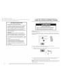
IMPORTANT: Read all instructions before operating.
PD Models: Insert access door key, turn, and lift to remove access doon
PR Models: Once the debit card reader is installed (according to the reader manufacturing
instructions), the setup mode can be entered by inserting a manual setup card (supplied by
the reader manufacturer) into the card slot. If a manual setup card is not available, manual
setup mode can be entered by removing connector AA] on the circuit board.
Electrical Shock Hazard
Disconnect power before servicing.
Replace all parts and panels before operating.
Failure to do so can result in death or electrical shock.
IMPORTANT: Unplug washer or disconnect power before opening the console.
To access connector AA1, disconnect poweb open console, disconnect plug on AA1, close
console.
Electrical Shock Hazard
Plug intoa grounded 3 prong outlet.
Do not remove ground prong.
Do not use an adapter.
Do not use an extension cord.
Failureto follow these instructions can result in death,
fire, or electrical shock.
The display can contain 4 numbers and/or letters and a decimal point. These are used to
indicate the setup codes and related code values available for use in programming the
appliance.
HOW TO USE THE KEYPADS TO PROGRAM THE CONTROLS
1. The PERMANENT PRESS keypad is used to adjust the values associated with setup codes.
Pressing the keypad will change the value by increments. Rapid adjustment is possible by
holding the keypad down.
2. The WOOI_ENS keypad will advance you through the setup codes. Pressing the keypad
will advance you to the next available setup code. Holding the keypad down will
automatically advance through the setup codes at a rate of 1 per second.
3. The DEI.ICATES & KNITS keypad is used to select or dese[ect options.
Before proceeding, it is worth noting that, despite all of the options available, an owner can
simply choose to un-crate a new commercial washer, hook it up, plug it in, and have a unit
which operates.
Units are preset at the factory for a 14-minute wash period and 3 rinses (no extra rinse).
SETUP CODES
The WOOI_ENS keypad will advance you from code to code. The PERMANENT PRESS
keypad will change the code value. The DEI.ICATES & KNITS keypad will select or dese[ect
options.
FOR PR MODEl_S: The setup codes are the same as for the "PD" mode[ except where noted.
The setup code is indicated by the one or two left-hand characters. The setup code value is
indicated by the two or three right-hand characters.
CODE EXPLANATION
607 6 REGULAR CYCLE PRICE
07
Represents the number of quarters (coin 1); may adjust from 0-39. (See VAI.UE
OF COIN 1.) Advance from 0-39 by pressing PERMANENT PRESS.
Currently set for 7 quarters = $1.75.
PR MODEl. ONI.Y: Currently set for 0 quarters.
PS MODE ONI.Y: Represents the number of push-in actuations of the coin slide
to start the washer.
601 setting would represent one coin slide actuation.
Press WOOI.ENS keypad once to advance to next code.
714 7 WASH LENGTH
14
This is the number of minutes for WASH. Unit comes from the factory preset
with 14 minutes. Choose from 9-17 minutes by pressing the PERMANENT
PRESS keypad.
Press WOOI.ENS keypad once to advance to next code.
iiiiiiiiiiir_
Plug in washer or reconnect power. The washer is now in the setup mode.
The lower fabric setting keypads and the digital display are used to set up the controls.

800 8 ADDITIONAL RINSE OPTION
This option is either SEI.ECTED "ON" or NOT SEI.ECTED "OFF."
00 Not Selected "OFF."
Ar Selected "ON."
Press DEI_ICATES & KNITS keypad once for this selection.
Press WOOI.ENS keypad once to advance to next code.
900 9 CYCLE COUNTER OPTION
This option is either SEI.ECTED "ON" or NOT SEI.ECTED "OFF."
00 Not Selected "OFF."
0C Selected "ON" and not able to be deselected. Press DEI_ICATES & KNITS
keypad 3 consecutive times to select "ON." Once selected "ON" it cannot be
deselected.
Press WOOLENS keypad once to advance to next code.
1.00 1. MONEY COUNTER OPTION
This option is either SEI.ECTED "ON" or NOT SEI.ECTED "OFF."
00 Not Selected "OFF."
0C Selected "ON."
Press DEI.ICATES & KNITS keypad 3 consecutive times to select "ON" and
3 consecutive times to remove (Not Selected "OFF"). Counter resets by going
from "OFF" to "ON."
Press WOOI.ENS keypad once to advance to next code.
CO Selected "ON" and not able to be dese[ected. To select "ON" and not able to
be dese[ected, first select "ON," then within 2 seconds, press DEI.ICATES &
KNITS twice, PERMANENT PRESS once, and exit setup mode.
2.00 2. SPECIAL PRICING OPTIONS
This option is either SEI.ECTED "ON" or NOT SEI.ECTED "OFF."
00 Not Selected "OFF."
SP Selected "ON."
Press DEI.ICATES & KNITS keypad once for this selection.
If SPECIAl. PRICING OPTION is selected, you have access to codes 3.XX through 9.XX.
Press WOOI.ENS keypad once to advance to next code.
Options to use if SPECIAL PRICING is selected.
3.07 3. SPECIAL CYCLE PRICE
07 Represents the number of quarters (coin 1); may adjust from 0-39. (See VAI.UE
OF COIN 1.) Advance from 0-39 by pressing PERMANENT PRESS.
Currently set for 7 quarters = $1.75
PR MODEl_ ONLY: Currently set for 0 quarters.
Press WOOI.ENS keypad once to advance to next code.
5.00 5. TIME-OF-DAY CLOCK, MINUTES
00 This is the TME-OF-DAY CI_OCK, minute setting; select 0-59 minutes by
pressing PERMANENT PRESS keypad.
Press WOOI_ENS keypad once to advance to next code.
6.00 6. TIME-OF-DAY CLOCK, HOURS
(NOTE: Uses military time or 24 hr. clock)
_xS
00 This is the TIME-OF-DAY CI_OCK, hour setting; select 0-23 hours by pressing
PERMANENT PRESS keypad.
Press WOOI_ENS keypad once to advance to next code.
7.00 7. SPECIAL PRICE START HOUR
(NOTE: Uses military time or 24 hr. clock)
00 This is the start hour; 0-23 hours. Select START HOUR by pressing
PERMANENT PRESS keypad.
Press WOOLENS keypad once to advance to next code.
8.00 8. SPECIAL PRICE STOP HOUR
(NOTE: Uses military time or 24 hr. clock)
00 This is the stop hour; 0-23 hours. Select STOP HOUR by pressing
PERMANENT PRESS keypad.
Press WOOLENS keypad once to advance to next code.
9.10 9. SPECIAL PRICE DAY
10 This represents the day of the week and whether special pricing is selected for
that day. A number followed by "0" indicates no selection that particular day
(9.10). A number followed by an "S" indicates selected for that day (9.1S). To
change the value of "0" and "S," use the "DEI.ICATES & KNITS" key.
Days of the week (1-7) are selected by pressing PERMANENT PRESS keypad.
When exiting setup code "9.", it must show current day of week.
Days of the week SPECIAl_ PRICE DAY
If selected, would show
10 Day 1 Sunday 1S
20 Day 2 Monday 2S
30 Day 3 Tuesday 3S
40 Day 4 Wednesday 4S
50 Day 5 Thursday 5S
60 Day 6 Friday 6S
70 Day 7 Saturday 7S
Press WOOI.ENS keypad once to advance to next code
14

A.00 A. VAULT VIEWING OPTION
This option is either SEI.ECTEI) "ON" or NOT SEI.ECTEI) "OFF."
00 Not Selected "OFF."
SC SC Selected "ON."
Press I)EI_ICATES & KNITS keypad once for this selection. When selected, the
money and/or cycle counts will be viewable (if counting is selected), when the
coin box is removed.
Press WOOI_ENS keypad once to advance to next code.
b.05 b.
05
VALUE OF COIN 1
This represents the value of coin 1 in number of nickels. 05 = $0.25.
By pressing PERMANENT PRESS keypad you have the option of 1-199 nickels.
PS MODE ONI.Y: Represents the total vend price in nickels.
Example: b.30 is equal to $1.50.
Press WOOI_ENS keypad once to advance to next code.
C.20 C.
20
VALUE OF COIN 2
This represents the value of coin 2 in number of nickels; 20 = $1.00.
PR MODEl. ONI_Y: Currently set for $0.25
By pressing PERMANENT PRESS keypad you have the option of 1-199 nickels.
Press WOOI.ENS keypad once to advance to next code.
d.00 d. COIN SLIDE OPTION
This option is either SEI.ECTED "ON" or NOT SEI.ECTED "OFF."
00 Not Selected "OFF."
CS CS Selected "ON."
Press DEI_ICATES & KNITS keypad 3 consecutive times for this selection. When
coin slide mode is selected, set b. equal to value of slide in nickels. Set Step 6
(regular cycle price) and Step 3 (special cycle price) to number of slide
operations. If the installer sets up "CS" on a coin drop model, it will not register
coins.
Press WOOI_ENS keypad once to advance to next code.
E.00 E. ADD COINS OPTION
This option is either SEI.ECTED "ON" or NOT SEI.ECTED "OFF."
This option causes the customer display to show the number of coins (coin 1)
to enter, rather than the dollars-and-cents amount.
00 Not Selected "OFF."
AC Selected "ON."
Press DEI_ICATES & KNITS keypad 3 consecutive times for this selection.
Press WOOI.ENS keypad once to advance to next code.
F.00 F. ENHANCED PRICING OPTION
00 Not Selected "OFF."
CP Cycle-Based pricing enabled. This option allows configuration of different
prices for cold, warm, and hot water cycles.
Su Super Cycle pricing enabled. This option allows customers to upgrade cycles
by depositing extra money. Setup codes "H." and "h." will be displayed only
when this option is enabled.
Press DEI_ICATES & KNITS keypad once for this selection.
Press WOOI_ENS keypad once to advance to next code.
H.01 H. SUPER CYCLE UPGRADE PriCE
(Skipped unless super cycle pricing is enabled.)
01 This represents the number of coin 1 required to upgrade a base cycle to a
super cycle.
Advance from 0-39 by pressing PERMANENT PRESS keypad.
Press WOOLENS keypad once to advance to next code.
h.01 h. SUPER CYCLE TYPE (Skipped unless Super Cycle pricing is enabled.)
01 This represents the super cycle upgrade option.
Press PERMANENT PRESS keypad to step through upgrade options 1-3 as
follows:
01 - enhanced wash, extra 3 minutes of wash tumble in addition to the
programmed wash time.
02 - extra rinse for all cycles.
03 - both 01 and 02.
Press WOOLENS keypad once to advance to next code.
J.Cd J. COIN/DEBIT OPTION
Cd Both coin and debit selected.
C Coins selected, debit disabled.
d Debit Card selected, coins disabled.
Press DEI.ICATES & KNITS keypad 3 consecutive times for this selection.
Ed Enhanced debit is self-selected when a Generation 2 card reader is installed in
the washer. The Ed option cannot be manually selected or dese[ected.
Press WOOI.ENS keypad once to advance to next code.
L.00 I..... PrIcE SUPPRESSION OPTION
This option causes the customer display to show "AI)D" or "AVAII_ABI_E" rather
than the amount of money to add. (Used mainly in debit installations.)
00 Not Selected "OFF."
PS PS Selected "ON."
Press DEI_ICATES & KNITS keypad once for this selection.
Press WOOI.ENS keypad once to advance to next code.

Whenselected,moneyheldinescrowfor30minuteswithoutfurtherescrow
orcycleactivitywillbecleared.
00 NotSelected"OFF."
CE Selected"ON."
PressDEI_ICATES&KNITSkeypadonceforthisselection.
PressWOOI.ENSkeypadoncetoadvancetonextcode.
r.800r.
800
TOP SPIN SPEEDRPM
This can be selected from the following spin speeds: 600 rpm, 750 rpm,
800 rpm, 1000 (displays as 999) rpm.
Step between speeds by pressing PERMANENT PRESS.
Currently set for 800 rpm.
PressWOOLENS keypad once to advance to next code.
U.00 U. PENNY INCREMENT OFFSET
00 This represents the penny increment price offset used in
Generation 2 (Enhanced Debit) PR models. Choose from 0-4 pennies by
pressing the PERMANENT PRESS keypad.
Press WOOI.ENS keypad once to advance to next code.
A1.00 A1. PREWASH LENGTH
00 This is the number of minutes of PREWASH.
Choose 0 to disable the prewash or select between 2 and 7 minutes by
pressing the PERMANENT PRESS keypad.
Press WOOI_ENS keypad once to advance to next code.
A2.03 A2. FINAL SPIN LENGTH
03 This is the number of minutes of final high speed spin. Choose from
3-8 minutes by pressing the PERMANENT PRESS keypad.
Press WOOI.ENS keypad once to advance to next code.
If cycle counter (90C) is selected, the following is true:
100 Represents the number of cycles in HUNDREDS
200 Represents the number of cycles in ONES
Total = 225 cycles
This is "VIEW ONI.Y" and cannot be cleared.
1 02 = 200
2 25 = 25
Press WOOI.ENS keypad once to advance to next code.
If money counter (1.0C or 1.C0) is selected, the following is true:
300 Number of dollars in HUNDREDS
400 Number of dollars in ONES
500 Number of CENTS.
3 01 = 100
4 68 = 68
5 75 = 75
Total =$168.75
END of SETUP PROCEDURES.
EXIT FROM SETUP MODE
PI]) Models: Reinstall access door.
PR Modem: Remove power, open console, reinsert plug into AA1, close console, and apply
power.
To enter the "Washer Diagnostic Mode," first enter "Start Operating Setup." Then press and
hold the DEI_ICATES & KNITS key for 1 second while in any of the setup codes one through
six, anytime a diagnostic code is present, or while dAS displays if operating with Maytag Data
Acquisition setup.
On entry to diagnostic mode the entire display will flash, a cycle in process is canceled,
money in escrow is cleared, and diagnostic codes are cleared. If a diagnostic code persists, it
must be corrected before the following cycle options are permitted.
There are five possible ways to initiate cycle activity from diagnostic mode as follows:
1. Clean Washer cycle - With the entire display flashing, this cycle is started by pressing the
BRIGHTS keypad.
Use the Clean Washer cycle once a month to keep the inside of your washer fresh and
clean. This cycle uses a higher water level. Use with AFFRESH r_ washer cleaner tablet or
liquid chlorine bleach to thoroughly clean the inside of your washing machine. This cycle
should not be interrupted. See "Cleaning Your Washer."
IMPORTANT: Do not place garments or other items in the washer during the Clean
Washer cycle. Use this cycle with an empty wash drum.
2. Cycle Credit - With the entire display flashing, a cycle may be credited by pressing the
PERMANENT PRESS keypad (CC will display). When the service mode is exited "SEI.ECT
CYCI E" will be displayed unless the end-of-cycle door opening is required.
3. Manual I_oad Test Cycle - With the entire display flashing, this cycle is started by pressing
the WHITES keypad. This cycle provides more typical full length fills, tumbles, drains and
actuator dispenser movement allowing for a more thorough analysis of the washer
operation, including pressure switch behavior.
4. Quick Spin Cycle - With the entire display flashing, this cycle is started by pressing the
COl_ORS keypad. This cycle provides a method to quickly drain and spin (remove water
from the washer) if desired.
5. History Overview Test Cycle - With the entire display flashing, this cycle is started by
pressing the WOOI_ENS keypad. This cycle provides a quick verification that the cold and
hot water valves, dispensers, and pump motor are working and actuator dispenser
movement. It also includes drain and spin operations.
Pressing the DELICATES & KNITS keypad will exit diagnostic mode and cancel a diagnostic
cycle in process.
16

DIAGNOSTIC CODES
If the setup mode is entered and one of the following has occurred, the appropriate diagnostic
code will be in the display.
d5
d9
d13
d16
F20
F22
Blocked coin 1 or coin drop control circuit failure (coin recognition and price
display disabled while blockage persists). PR Models Only: Setup mode J. should
be set to _d (or Ed if in Enhanced Debit) to eliminate coin related diagnostic
codes.
Voltage detected below 90 vac for 8 seconds.
Blocked coin 2 or coin drop control circuit failure
(coin recognition and price display disabled while blockage persists).
Not receiving communications from installed debit card reader in
Generation 2 debit mode.
Slow Fill. The washer will not detect water input for 4 min. Pressure switch failure
or no water inlet. This code is reported as d8 on d7
The door is not able to lock. Door lock error or someone trying to start the washer,
by pressing the door switch with the finger. This code is reported as dl 7 on Accu
Trac.
(For different code consult service personnel)
WASHER HELP MODE
This mode is entered by pressing the PERMANENT PRESS keypad while in special pricing
option mode 2.XX (or while dAS displays if operating with Maytag Data Acquisition setup).
In help mode, other display symbols and elements are mapped to reflect the state of various
inputs and outputs as follows:
Wash
Circle above digit
DOOR I.OCKED
COI.I)
HOT
OR
AVAII.ABI.E
Water sensed at wash level
I.ow voltage present (below about 90 vac)
Door closed
I)oor sensed locked
Cold water relay on
Hot water relay on
Door unlock
I)rain pump ON
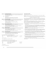
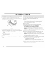
Cleaning the Door Seal/Bellow
Open the washer door and remove any clothing or items from the washer.
Inspect the black colored seal/bellow between the door opening and the basket for
stained areas. Pull back the seal/bellow to inspect all areas under the seal/bellow and to
check for foreign objects.
3. If stained areas are found, wipe down these areas of the seal/bellow, using the procedure
that follows.
a) Mix a dilute solution, using 3/4 cup (177 ml.) of liquid chlorine bleach, and 1 gal.
(3.8 I.) of warm tap water.
b) Wipe the seal/bellow area with the dilute solution, using a damp cloth.
c) I.et stand 5 minutes.
d) Wipe clown area thoroughly with a dry cloth and let the washer interior air dry with
door open.
IMPORTANT:
• Wear rubber gloves when cleaning for prolonged periods.
• Refer to the bleach manufacturer's instructions for proper use.
Washer Maintenance Procedure
This washer has a special cycle that uses higher water volumes in combination with
AFFRESH rM washer cleaner or liquid chlorine bleach to thoroughly clean the inside of the
washer.
1.
2.
S
A NOTES:
A. Seal/Bellow
• Read these instructions completely before beginning the cleaning process.
If necessary, the cleaning cycle may be interrupted by pressing the I)EI_ICATES & KN ITS
button twice. However; this will not immediately stop the cycle. The machine will
continue with several rinse and drain steps to ensure that all remaining bleach is rinsed
from the washer.

Begin procedure
1. Open the washer door and remove any clothing or items from the washer.
2. Using the AEERESHTM washer cleaner (Recommended):
Add one AFFRESHrMwasher cleaner tablet to the washer drum.
3.
4.
If using liquid chlorine bleach:
Open the dispenser drawer and immediately add 2/3cup (160 ml.) of liquid chlorine
bleach to the bleach compartment.
NOTE: Do not add any detergent to this cycle. Use of more than 2/3cup (160 ml.) of
bleach will cause product damage over time.
Close the washer door and the dispenser drawer.
To start the Clean Washer cycle, first enter "Start Operating Setup." Then press and hold
DEI_ICATES & KNITS for 1 second. With the entire display flashing, press BRIGHTS.
NOTE: The basket will rotate, then the door will unlock, lock again, and then the cycle
will continue.
• The machine will not fill, but the basket will rotate while the washer runs a short
sensing cycle. This will take approximately 3 minutes.
5. The cycle will determine whether clothing or other items are in the washer.
a) If no items are detected in the washeb it will proceed to Step 7.
b) If any items are detected in the washer, "rl." or "F-34" will be displayed. Then the
door will unlock.
• Press DEI_ICATES & KNITS to cancel the failure code. Then repeat steps 1,3
and 4 to start the cycle again.
6. Once the cycle has begun, allow the cycle to complete.
7. After the cycle is complete, leave the door open slightly, to allow for better ventilation and
drying of washer interior.
Always do the following to maintain washer freshness
• Use only HE High Efficiency detergent.
• I.eave the door slightly open after each cycle to allow for better ventilation and drying of
washer interior.
Clean the washer monthly using the Washer Maintenance Procedure, an AFFRESH rM
tablet or2/a cup (160 ml.) of liquid chlorine bleach.
If the procedure does not sufficiently improve the machine freshness, please evaluate your
installation and usage conditions for other causes.
Cleaning the exterior
Use a soft damp cloth or sponge to wipe up any spills. Occasionally wipe the outside of your
washer to keep it looking new. Use mild soap and water. Do not use abrasive products.
Cleaning the dispenser drawer
The dispenser drawer is removable for easy cleaning.
1. Unlock the dispenser drawer by pressing the Release I.ever. Remove the drawer.
2. Remove the inserts (the siphon from the softener and bleach compartments).
3. Wash the parts under running water.
NOTE: Do not wash components in the dishwasher.
4. Replace the inserts and return the dispenser to the drawer.
Replace inlet hoses after 5 years of use to reduce the risk of hose failure. Periodically inspect
and replace inlet hoses if bulges, kinks, cuts, wear or leaks are found.
When replacing your inlet hoses, record the date of replacement.
If you need assistance:
The Maytag Consumer Interaction Center will answer any questions about operating or
maintaining your washer not covered in the Installation Instructions. The Maytag Consumer
Interaction Center is open 24 hours a day, 7 days a week. Just dial 1-800 NO BELTS
(1-800-662-3587) - the ca[[ is free.
When you ca[[, you will need the washer mode[ number and serial number. Both numbers
can be found on the serial-rating plate located on your appliance.
Enhance your washer with these premium accessories.
For more high-quality items or to order, ca[[ 1-800-901-2042, or visit us at www.maytag.com/
accessories. In Canada ca[[: 1-800-807-6777 or visit us at www.whirlpoolparts.ca.
Part Number Accessor
8212638RP 6 ft (1.8 m) nylon braided space-saving fill hose, 90 ° elbow, hypro-
blue steel couplings. Safer than stainless steel (2-pack)
8212487RP 5 ft (1.5 m) nylon braided fill hose. Safer than stainless steel (2-pack)
8212526 Washer drip tray, fits under all
31682 All purpose appliance cleaner
1903WH I.aundry supply storage cart
W10135699 AFFRESH _'_*washer cleaner
18 ....

LIMITED WARRANTY ON PARTS
For the first fiveyears from the date of purchase, when this commercial appliance is installed, maintained and operated according to the instructions attached to or furnished with the product,
Maytag brand of Whirlpool Corporation (thereafter "Maytag") will pay for factory specified parts or original equipment manufacturer parts to correct defects in materials or workmanship. Proof
of original purchase date is required to obtain service under this warranty.
1.
2.
3.
4.
5°
6.
7.
8.
9.
ITEMS MAYTAG WILL NOT PAY FOR
All other costs including labor, transportation, or custom duties.
Service calls to correct the installation of your commercial appliance, to instruct you how to use your commercial appliance, to replace or repair fuses, or to correct external wiring or
plumbing.
Repairs when your commercial appliance is used for other than normal, commercial use.
Damage resulting from improper handling of product during delivery, theft, accident, alteration, misuse, abuse, fire, flood, acts of God, improper installation, installation not in accordance
with local electrical or plumbing codes, or use of products not approved by Maytag.
Pickup and Delivery. This commercial appliance is designed to be repaired on location.
Repairs to parts or systems resulting from unauthorized modifications made to the commercial appliance.
The removal and reinsta[[ation of your commercial appliance if it is installed in an inaccessible location or is not installed in accordance with published installation instructions.
Chemical damage is excluded from all warranty coverage.
Changes to the building, room, or location needed in order to make the commercial appliance operate correctly.

DISCLAIMER OF IMPLIED WARRANTIES; LIMITATIONS OF REMEDIES
CUSTOMER'S SOLE AND EXCI.USIVE REMEDY UNDER THIS I_IMITED WARRANTY SHALl_ BE PRODUCT REPAIR AS PROVIDED HEREIN. IMPHED WARRANTIES, INCI_UDING
WARRANTIES OF MERCHANTABII.ITY OR FITNESS FOR A PARTICULAR PURPOSE, ARE HMITED TO ONE YEAR OR THE SHORTEST PERIOD AI_I_OWED BY LAW. WHIRl_POOL SHAI.I ....
NOT BE LIABLE FOR INCIDENTAL OR CONSEQUENTIAl_ DAMAGES. SOME STATES AND PROVINCES DO NOT AI_I_OW THE EXCLUSION OR I_IMITATION OF INCIDENTAl. OR
CONSEQUENTIAl_ DAMAGES, OR I_IMITATIONS ON THE DURATION OF IMPLIED WARRANTIES OF MERCHANTABILITY OR FITNESS, SO THESE EXCI.USIONS OR I_IMITATIONS MAY
NOT APPI.Y TO YOU. THIS WARRANTY GIVES YOU SPECIFIC I.EGAI. RIGHTS AND YOU MAY AI.SO HAVE OTHER RIGHTS, WHICH VARY FROM STATE TO STATE OR PROVINCE TO
PROVINCE.
If you need service, please contact your authorized Maytag Commercial I.aundry distributor. To locate your authorized Maytag Commercial I.aundry distributor, or for web inquMes, visit
www.MaytagCommerciall.au ndry.com.
9/07
For written correspondence:
Maytag Commercial Laundry Service Department
2000 M-63 North
Benton Harbor, Michigan 49085 USA
Keep this book and your sales slip together for future reference. You must provide
proof of purchase or installation date for in-warranty service.
Write down the following information about your major appliance to better help you obtain
assistance or service if you ever need it. You will need to know your complete model
number and serial number. You can find this information on the model and serial number
label located on the product.
Dealer name
Address
Phone number
Model number
Serial number
Purchase date
20
La page est en cours de chargement...
La page est en cours de chargement...
La page est en cours de chargement...
La page est en cours de chargement...
La page est en cours de chargement...
La page est en cours de chargement...
La page est en cours de chargement...
La page est en cours de chargement...
La page est en cours de chargement...
La page est en cours de chargement...
La page est en cours de chargement...
La page est en cours de chargement...
La page est en cours de chargement...
La page est en cours de chargement...
La page est en cours de chargement...
La page est en cours de chargement...
La page est en cours de chargement...
La page est en cours de chargement...
La page est en cours de chargement...
La page est en cours de chargement...
-
 1
1
-
 2
2
-
 3
3
-
 4
4
-
 5
5
-
 6
6
-
 7
7
-
 8
8
-
 9
9
-
 10
10
-
 11
11
-
 12
12
-
 13
13
-
 14
14
-
 15
15
-
 16
16
-
 17
17
-
 18
18
-
 19
19
-
 20
20
-
 21
21
-
 22
22
-
 23
23
-
 24
24
-
 25
25
-
 26
26
-
 27
27
-
 28
28
-
 29
29
-
 30
30
-
 31
31
-
 32
32
-
 33
33
-
 34
34
-
 35
35
-
 36
36
-
 37
37
-
 38
38
-
 39
39
-
 40
40


Maytag MAH22PDAWW0 Installation Instructions Manual
- Catégorie
- Machines à laver
- Taper
- Installation Instructions Manual
- Ce manuel convient également à
dans d''autres langues
- English: Maytag MAH22PDAWW0
Documents connexes
-
Maytag MHN31PRAWW Installation Instructions Manual
-
Maytag MAH22PDAGW0 Guide d'installation
-
-
Maytag MLG20PDCWW0 Guide d'installation
-
-
-
-
-
-