Garland GI-BH/IN 2500 Owner Instruction Manual
- Catégorie
- Cuisinières
- Taper
- Owner Instruction Manual

Part Number 1955203 rev 4 4/15
Installation, Operation and Maintenance Manual
This manual is updated as new information and models are released. Visit our website for the latest manual.
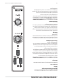
Master Series
Full-Size Electric Convection Ovens
models
MCO-ES-10S
MCO-ED-10S
MCO-ES-20S
MCO-ED-20S
MCO-ES-10
MCO-ED-10
MCO-ES-20
MCO-ED-20
MCO-ES-10

Part Number 1955203 rev 4 4/152
Users are cautioned that maintenance and repairs must be performed by a Garland authorized service agent
using genuine Garland replacement parts. Garland will have no obligation with respect to any product that has been
improperly installed, adjusted, operated or not maintained in accordance with national and local codes or installation
instructions provided with the product, or any product that has its serial number defaced, obliterated or removed,
or which has been modified or repaired using unauthorized parts or by unauthorized service agents.
For a list of authorized service agents, please refer to the Garland web site at http://www.garland-group.com.
The information contained herein, (including design and parts specifications), may be superseded and is subject
to change without notice.
FOR YOUR SAFETY:
DO NOT STORE OR USE GASOLINE
OR OTHER FLAMMABLE VAPORS OR
LIQUIDS IN THE VICINITY OF
THIS OR ANY OTHER
APPLIANCE
WARNING:
IMPROPER INSTALLATION, ADJUSTMENT,
ALTERATION, SERVICE OR MAINTENANCE
CAN CAUSE PROPERTY DAMAGE, INJURY,
OR DEATH. READ THE INSTALLATION,
OPERATING AND MAINTENANCE
INSTRUCTIONS THOROUGHLY
BEFORE INSTALLING OR
SERVICING THIS EQUIPMENT
PLEASE READ ALL SECTIONS OF THIS MANUAL
AND RETAIN FOR FUTURE REFERENCE.
THIS PRODUCT HAS BEEN CERTIFIED AS
COMMERCIAL COOKING EQUIPMENT AND
MUST BE INSTALLED BY PROFESSIONAL
PERSONNEL AS SPECIFIED.
INSTALLATION AND ELECTRICAL CONNECTION
MUST COMPLY WITH CURRENT CODES:
IN CANADA - THE CANADIAN ELECTRICAL
CODE PART 1 AND / OR LOCAL CODES.
IN USA – THE NATIONAL ELECTRICAL CODE
ANSI / NFPA – CURRENT EDITION.
ENSURE ELECTRICAL SUPPLY CONFORMS WITH
ELECTRICAL CHARACTERISTICS SHOWN ON
THE RATING PLATE.
SAFETY NOTICES
WARNING:
This product contains chemicals known to the state of California to cause cancer and/or birth defects or other
reproductive harm. Installation and servicing of this product could expose you to airborne particles of glass wool/
ceramic fibers. Inhalation of airborne particles of glass wool/ceramic fibers is known to the state of California to cause
cancer.
Notice: CE models discontinued (manufactured up to October, 2014).
Power Failure
In the event of a power failure, no attempt should be
made to operate this oven.

Part Number 1955203 rev 4 4/15 3
TABLE OF CONTENTS
SAFETY NOTICES. . . . . . . . . . . . . . . . . . . . . . . 2
GENERAL INFORMATION . . . . . . . . . . . . . . . 5
Model Numbers . . . . . . . . . . . . . . . . . . . . . . . . . . . . . 5
Warranty . . . . . . . . . . . . . . . . . . . . . . . . . . . . . . . . . . . . 5
Serial Plate Location . . . . . . . . . . . . . . . . . . . . . . . . . . 5
Accessories . . . . . . . . . . . . . . . . . . . . . . . . . . . . . . . . . . 5
DIMENSIONS AND SPECIFICATIONS, MCO
ED/ES 10/20 . . . . . . . . . . . . . . . . . . . . . . . . . . . 6
DIMENSIONS AND SPECIFICATIONS, MCO
ED/ES 10/20 S. . . . . . . . . . . . . . . . . . . . . . . . . . 7
INSTALLATION . . . . . . . . . . . . . . . . . . . . . . . . . 8
Entry Clearance . . . . . . . . . . . . . . . . . . . . . . . . . . . . . . 8
Installation Clearance . . . . . . . . . . . . . . . . . . . . . . . . 8
Installation of Double Deck Models . . . . . . . . . . . 8
Electrical Connections . . . . . . . . . . . . . . . . . . . . . . . . 9
OPERATING INSTRUCTIONS. . . . . . . . . . . . 10
Master 200 Solid State Control with
Electromechanical Timer . . . . . . . . . . . . . . . . . . . 10
Modes . . . . . . . . . . . . . . . . . . . . . . . . . . . . . . . . . . 10
Fan Speed . . . . . . . . . . . . . . . . . . . . . . . . . . . . . . 10
Lights. . . . . . . . . . . . . . . . . . . . . . . . . . . . . . . . . . . 10
Cool Down. . . . . . . . . . . . . . . . . . . . . . . . . . . . . . 10
Temperature . . . . . . . . . . . . . . . . . . . . . . . . . . . . 10
Timer . . . . . . . . . . . . . . . . . . . . . . . . . . . . . . . . . . . 11
Master 450 Electronic Control with
Cook-N-Hold and Master 455 Electronic Control
with Cook-N-Hold & Core Probe . . . . . . . . . . . . . 11
Modes . . . . . . . . . . . . . . . . . . . . . . . . . . . . . . . . . . 11
Controller Keys . . . . . . . . . . . . . . . . . . . . . . . . . . 11
Fahrenheit/Celsius. . . . . . . . . . . . . . . . . . . . . . . 12
Operating the Controls . . . . . . . . . . . . . . . . . . 13
Cook-N-Hold Operation . . . . . . . . . . . . . . . . . 13
Core Probe Operation . . . . . . . . . . . . . . . . . . . 13
Setting Setback Feature . . . . . . . . . . . . . . . . . 13
Master 475 Electronic Programmable Control 14
Manual Cooking. . . . . . . . . . . . . . . . . . . . . . . . . 14
Manual cooking using Cook-N-Hold. . . . . . 14
Programming Product Keys (Master 475) . 14
Cooking Using The Product Keys
(Master 475). . . . . . . . . . . . . . . . . . . . . . . . . . . . . 15
Verifying Hold Time (Master 475). . . . . . . . . 16
Selecting Fahrenheit or Celsius (Master 475) . . 16
Cooking With The Shelf Timer (Master 475) . .
16
PERFORMANCE RECOMMENDATIONS AND
GENERAL SAFETY PRECAUTIONS. . . . . . . 17
PROBLEM/SOLUTIONS . . . . . . . . . . . . . . . . 18
COOKING GUIDE . . . . . . . . . . . . . . . . . . . . . . 19
COOK AND HOLD . . . . . . . . . . . . . . . . . . . . .20
CLEANING AND MAINTENANCE . . . . . . . . 21
Break-In Period . . . . . . . . . . . . . . . . . . . . . . . . . . . . . 21
Exterior Cleaning . . . . . . . . . . . . . . . . . . . . . . . . . . . 21
Interior Cleaning . . . . . . . . . . . . . . . . . . . . . . . . . . . . 21
Fan Area Maintenance . . . . . . . . . . . . . . . . . . . . . . 21
Motor Care . . . . . . . . . . . . . . . . . . . . . . . . . . . . . . . . .21

THIS PAGE INTENTIONALLY LEFT BLANK

Part Number 1955203 rev 4 4/15 5
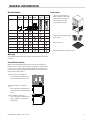
GENERAL INFORMATION
Model Numbers
Model Standard
Depth
Deep
Depth
Single
Deck
Double
Deck
Master
200
Control
Digital
Control
MCO-ES-10S
MCO-ED-10S
MCO-ES-20S
MCO-ED-20S
MCO-ES-10
MCO-ED-10
MCO-ES-20
MCO-ED-20
Warranty
Visit www.Garland-Group.com to view or download a copy of your
warranty.
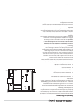
Serial Plate Location
When corresponding with the factory or your local authorized
factory service center regarding service problems or replacement
parts, be sure to refer to the particular unit by the correct model
number (including the prefix and suffix letters and numbers) and
the warranty serial number.
Ovens Built prior to 31-MAR-2011
• The serial plate is affixed to the
inside of the lower front cover.
Ovens Built between 01-APR-2011
and
• The serial plate is affixed to the
lower left corner of the left body
panel.
Ovens Built after 02-FEB-2015
• The serial plate is affixed to the
upper right corner of the left
body panel.
Accessories
• Stainless steel open base
with rack guides and shelf
(in lieu of 25-inch legs) for
extra rack/pan storage,
single deck oven only
• Swivel Casters (set of 4) with
front brakes
• Extra oven rack
• Removable stainless steel drip pan

Part Number 1955203 rev 4 4/156
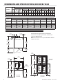
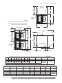
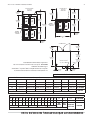
DIMENSIONS AND SPECIFICATIONS, MCO ED/ES 10/20
7-3/4"
[197mm]
MCO-ES
41-1/4"
[1048mm]
MCO-ED
44-1/2"
[1130mm]
38-1/4"
[972mm]
3/4"
[19mm]
17-3/4"
[451mm]
TOP VIEW
38"
[965mm]
32-1/8"
[816mm]
57-1/2"
[1461mm]
25-3/8"
[645mm]
SINGLE DECK
FRONT VIEW
1-1/4"
[32mm]
32-1/8"
[816mm]
32-1/8"
[816mm]
70-1/2"
[1791mm]
6-1/4"
[159mm]
1-1/4"
[32mm]
DOUBLE DECK
FRONT VIEW
FLUE: 2-3/8" x 5"
[60mm x 127mm]
REAR
CABLE
ENTRANCE
REAR CABLE
ENTRANCE
11-1/2"
[292mm]
1-11/16"
[43mm]
28-3/8"
[721mm]
32-1/8"
[816mm]
9-1/4"
[235mm]
Model**
Total
kW
Load
Nominal Amperes Per Line (includes 3/4 HP fan motor)
208V/
1Ph
240V/
1Ph
208V/3Ph 240V/3Ph 460V/3Ph 380V/3Ph** 415V/3Ph
XYZXYZXYZXYZXYZ
MCO-ES-10 10.4 50 43 30 30 28 26 26 24 14 14 13 15 13 13 16 14 14
MCO-ED-10 10.4 50 43 30 30 28 26 26 24 14 14 13 15 13 13 16 14 14
**Total kW rating for 380/3 phase models is 9.0
Model
Interior Dimensions (per oven) Exterior Dimensions Ship Info.
W:In(mm) H:In(mm) D:In(mm) W:In(mm) H:In(mm) D:In(mm) Lbs./Kg Cu. Ft.
MCO-ES-10 29 (736) 24 (610) 24 (610) 38 (965) 57-1/2 (1461) 41-1/4 (1048) 515/230 64
MCO-ES-20 29 (736) 24 (610) 24 (610) 38 (965) 70-1/2 (1791)* 41-1/4 (1048) 1030/465 128
MCO-ED-10 29 (736) 24 (610) 28 (711) 38 (965) 57-1/2 (1461) 44-1/2(1130) 545/245 64
MCO-ED-20 29 (736) 24 (610) 28 (711) 38 (965) 70-1/2 (1791)* 44-1/2(1130) 1090/490 128
* Height with legs or with standard casters. Height with low profile casters (double deck) is 68-1/2” (1740mm).
Standard electrical speci cations include motor
requirements. 3/4 HP, 2-speed motor, 1140/950 and
1725/1140 RPM, 60/50 Hz.
NOTE: Double deck ovens are provided with individual
supply connections.
Notice: CE models discontinued (manufactured up to October, 2014).

Part Number 1955203 rev 4 4/15 7
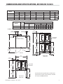
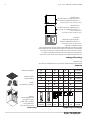
DIMENSIONS AND SPECIFICATIONS, MCO ED/ES 10/20 S
7-3/4"
[197mm]
38-1/4"
[972mm]
3/4"
[19mm]
17-3/4"
[451mm]
TOP VIEW
38"
[965mm]
32-1/8"
[816mm]
25-3/8"
[645mm]
SINGLE DECK
FRONT VIEW
1-1/4"
[32mm]
32-1/8"
[816mm]
32-1/8"
[816mm]
6-1/4"
[159mm]
1-1/4"
[32mm]
DOUBLE DECK
FRONT VIEW
FLUE: 2-3/8" x 5"
[60mm x 127mm]
11-1/2"
[292mm]
28-3/8"
[721mm]
REAR CABLE
ENTRANCE
1-11/16"
[43mm]
9-1/4"
[235mm]
32-1/8"
[816mm]
REAR CABLE
ENTRANCE
D
H
H
Standard electrical speci cations include motor
requirements. 3/4 H.P., 2 speed motor, 1140/950
and 1725/1140 RPM, 60/50 Hz.
Model
Interior Dimensions (per oven) Exterior Dimensions Ship Info.
W:In(mm) H:In(mm) D:In(mm) W:In(mm) H:In(mm) D:In(mm) Lbs./Kg Cu Ft
MCO-ES-10S
29(436) 24(610) 24(610) 38(965) 57-1/2(1416)
41-1/4 (1048)
515/230 64
MCO-ES-20S
29(436) 24(610) 24(610) 38(965) 70-1/2(1791)*
41-1/4 (1048)
1030/465 128
MCO-ED-10S
29(436) 24(610) 28(711) 38(965) 57-1/2(1416)
44-1/2(1130)
545/245 64
MCO-ED-20S
29(436) 24(610) 28(711) 38(965) 70-1/2(1791)*
44-1/2(1130)
1090/490 128
* Height with or without standard casters. Height with low pro le casters (double deck) is 68-1/2" (1740mm).
Model**
Total
kW
Load
Nominal Amperes Per Line (includes 3/4 HP fan motor)
208V/1Ph 240V/1Ph
208V/3Ph 240V/3Ph 460V/3Ph
XYZXYZXYZ
MCO-ES-10S 10.4 50 43 30 30 28 26 26 24 14 14 13
MCO-ED-10S 10.4 50 43 30 30 38 26 26 24 14 14 13
** NOTE: Double deck ovens are provided with individual supply connections

Part Number 1955203 rev 4 4/158
INSTALLATION
Entry Clearance
• Crated: 47” (1194mm)
• Uncrated: 32-1/2” (826mm)
Installation Clearance
NOTE: Always provide adequate clearance for maintenance
and operation.
• Installation adjacent to combustible and non-
combustible wall, minimum clearance:
Left Side Control Side Rear
Single-Deck 1" (26 mm) 1" (26 mm) 3" (77 mm)
Double-Deck 1" (26 mm) 2" (51 mm) 3" (77 mm)
• Installation near high heat producing equipment,
minimum clearance:
Left Side Control Side Rear
Single-Deck 1" (26 mm) 6" (153 mm) 3" (77 mm)
Double-Deck 1" (26 mm) 6" (153 mm) 3" (77 mm)
Notice
Avoid installing ovens near equipment, such as char-
broilers or fryers, which generate high heat and high
grease laden air.
• Clearance for Service (recommendation):
Control Side, minimum
Single-Deck 12" (305 mm)
Double-Deck 12" (305 mm)
NOTE: Install units with casters in very tight
locations for ease of service.
IMPORTANT Large objects should not be placed in front
of this oven, which would obstruct the air ow through the
front. Objects should not be placed on the main top rear
of the oven while in use because this could obstruct the
venting system. Install ovens where side body perforated
panels or control sections do not get sprayed with water
wash down spray hoses.
Installation of Ovens Equipped with Casters
A. For an appliance equipped with casters, the installation
shall be made with a connector that complies with the
Standard for Connectors for Movable Appliances, ANSI
Z21.69. Adequate means must be provided to limit the
movement of the appliance without depending on the
connector wiring.
B. The front casters of the unit are equipped with brakes to
limit the movement of the oven without depending on
the connector wiring to limit the appliance movement.
C. A restraint can be attached to the unit. If the restraint is
disconnected, be sure to reconnect the restraint after the
oven has been returned to its originally installed position.
Installation of Double Deck Models
A. Position insert in bottom leg opening and tap insert up
into leg until it seats at collar. Attach six inch (6”) legs to
lower oven section. Raise unit or lay on its left side. Place
the front legs on the oven so as to line up with four (4)
attaching bolt holes. Secure leg to oven frame using (4)
3/8-16 x 3/4 bolts and washers provided. Repeat at rear of
unit.
B. Remove lower front cover of top deck (located under
oven doors). Raise top deck into place and line up body
sides and back of the unit. Fasten the rear of the units
together, with the stacking bracket using (6) 1/4-20
machine screws, lock washers and nuts, (provided).
C. Install the interconnecting ue parts, carefully following
the instructions contained in the stacking kit. Pay
particular attention to the type of ovens you are stacking
and be sure to follow the corresponding instructions.
D. Check leveling of unit four (4) ways (using a common
carpenter’s level on the rack inside the oven).
E. Maintain clearance from combustibles.
CAUTION: Disconnect both ovens from electrical supply
before servicing to protect against shock!

Part Number 1955203 rev 4 4/15 9
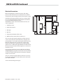
Electrical Connections
Before attempting the electrical connection, the rating
plate should be checked to ensure that the unit’s electrical
characteristics and the supply electrical characteristics agree.
Installation of the wiring must be made in accordance with
U.L. 197 Commercial Electric Cooking Appliance Standards,
Local and/or National Electrical Code,
ANSI/NFPA 70-1990, or the Canadian Electrical Code, CSA
C22.2 as applicable.
1. Switch panel size
2. Overload protection
3. Wire type
4. Wire size
5. Temperature limitations of the wires
6. Method of connection (Cable, Conduit, etc.)
The service line will enter through the rear of the unit and
is to be connected to the terminal block (see diagram). The
terminal block is accessed by removing the lower front cover.
Removal of the body side is not necessary. Install a main
disconnect switch and a separate fuse or breaker with this
appliance. Use a su cient length of exible conduit between
the main disconnect switch and the appliance so unit can be
moved for service.
Input voltage and phasing must match the units voltage
and phasing. Wiring diagram is attached to the main back of
each oven. Visually check all electrical connections. Energize
electric service to units.
The oven is wired per original factory order. If it is necessary
to change to single-phase or three-phase, please refer to kit
part number 4533009.
Service and unit voltage must agree.
INSTALLATION Continued

Part Number 1955203 rev 4 4/1510
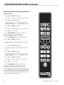
OPERATING INSTRUCTIONS
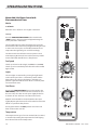
Master 200 Solid State Control with
Electromechanical Timer
Modes
In O Mode
When the oven is o , there are no lights or indicators.
Start Up
Press the COOK/OFF/COOL DOWN rocker switch to the
“COOK” position. The green lamp will light indicating the
oven is powered in cook mode.
The oven will begin to heat to the temperature set on the
thermostat dial. The amber lamp will light indicating the heat
is active. As the heat cycles on and o to maintain the set
temperature this light will go on and o accordingly.
The door must be closed for the oven to operate in cook
mode. Opening the door will cause the heat to stop and the
motor and fan will shut o . This is a safety feature.
Fan Speed
The fan speed can be either high (1725RPM) or (1150RPM).
The fan speed is controlled by the left rocker switch marked
high and low.
Lights
The oven lights are activated by pressing the light switch
on the control panel. This is a momentary switch and the
lights will stay lit as long as this button is held in the on
position. Lights will work whenever there is electrical power
connected to the oven.
Cool Down
Pressing the COOK/OFF/COOL down rocker switch to the
COOL DOWN position activates the fan and motor to cool
the oven cavity. The door must be open slightly for the fan
and motor to start. The heat is not active in this mode.
Optimal cool down will be achieved with the door open
slightly. Opening the door too far will shut the fan and motor
o . This is a patented safety feature.
Pressing the button to the OFF position cancels the cool
down and turns the oven o .
Temperature
The temperature range is from 150° to 500°F (66°C) to 250°C)
is controlled by rotating the temperature dial and aligning
the indicator to the desired temperature.

Part Number 1955203 rev 4 4/15 11
Timer
The timer is set by rotating the dial clockwise aligning the
indicator to the desired time cycle. The timer will count down
from 2 minutes to 60 minutes. At the end of the timing cycle
the buzzer will sound. The buzzer is turned o by rotating the
dial counter-clockwise to the o position.
NOTE: The timer does not control heating.
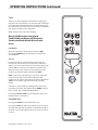
Master 450 Electronic Control with
Cook-N-Hold and Master 455 Electronic
Control with Cook-N-Hold & Core Probe
Modes
In O Modes
When the controller is o , the display will show “OFF”.
Pressing the ON/OFF key will activate the controller into
Start Up Mode.
Start Up
In Start Up mode, the controller will heat to the last set
temperature, time and fan speed. The factory defaults are
350°F (177°C), 30 minutes and low fan speed. The display will
indicate “LO” when the oven is below the set temperature.
When the oven cavity reaches the set temperature and is
ready for operation the display will indicate “LOAD”.
NOTE: If the oven temperature goes above the requested
temperature the display will indicate “HI” If the oven
temperature goes above 575°(302°C) the display will indicate
“HELP” and an audible signal will sound. This is a safety
feature.
If the door is opened during a cooking mode, the fan and
heat will stop, and the display will indicate “DOOR” until the
door is closed. This is a patented safety feature.
Pressing the ACTUAL TEMP key will display the actual oven
temperature in 5° increments.
Controller Keys
Pressing the ON/OFF key will activate the oven.
Pressing the LIGHT key will turn the lights on for 30 seconds.
The lights will work if the controller is in the O mode. When
the door is opened, the light will come on and stay on for 30
seconds.
OPERATING INSTRUCTIONS Continued

Part Number 1955203 rev 4 4/1512
Pressing the FAN HIGH key will activate the higher fan speed
and light its LED.
Pressing the FAN LOW key will activate the lower fan speed
and light its LED.
Pressing the FAN PULSE key will activate the lower fan speed
and light its LED. The fan will be active for 30 seconds then
o for 30 seconds, and continuous this cycle.
Pressing the SETBACK key will cool the oven cavity to
a preprogrammed temperature, see: Setting “Set-Back”
Feature. The oven will automatically go into Setback mode
after the pre-programmed non-usage time. The display will
indicate “SETB”. This is an energy-saving feature.
Pressing the COOL DOWN key will deactivate the heat, turn
the fan on high and light its LED. This display will indicate
“OPEN DOOR” if the door is closed, prompting the user
to open the door slightly. With the door open slightly the
display will indicate “COOL”. The Cool down will operate
when the door is closed or opened slightly. Optimal cool-
down will be achieved with the door open slightly. When
the door opens wider, the Cool Down mode will deactivate
and the display will indicate “DOOR”. This is a patented safety
feature. Pressing the COOL DOWN key again will turn the
LED o and stop this mode. Pressing the ON/OFF key will
also cancel Cool down. Cool Down is not active during a
cook.
When the ON/OFF switch is pressed to turn the oven o and
the oven was above 200°F (93°C), the oven will go into an
AUTO COOL DOWN mode. In Auto cool Down, the oven will
run the fan on high until the oven cavity drops below 150°F
(66°C). During this time the display will indicate “AUTO”.
When the oven temperature drops below 150°F (66°C) the
oven turns o . This feature protects the oven motor from
premature failure. Optimal cool-down will be achieved with
door open slightly.
Fahrenheit/Celsius
Factory default is Fahrenheit (F). To change to
Celsius (C), press and hold in the “Phantom Key” located
to the right of “Cook/Hold” key. “F” appears in the display.
Continue to hold until “C” is displayed and then release the
“Phantom key”.
OPERATING INSTRUCTIONS Continued

Part Number 1955203 rev 4 4/15 13
Core Probe Operation
The Core Probe option (455 Controller Only) is only active
when the core probe is plugged into its connector. To set the
core temperature, rst plug the core probe into its connector.
The display will indicate “100” and the CORE TEMP LED will
be on. The operator then sets the temperature by rotating
the dial on the controller until the desired temperature is
shown on the display. Pressing the SET key stores the core
temperature and starts the cooking process.
To set the oven temperature, press the SET key again. The
TEMP LED will light and the oven temperature can be
set by rotating the dial on the controller until the desired
temperature is displayed. Pressing the SET key again will
light the HOLD LED allowing the operator to set the hold
temperature in the same manner.
NOTE: If the hold temperature is not set, the default
hold temperature is 150°F (66°C) or the last programmed
temperature. (Hold temperature range is 140°F (60°C) to
210°F (99°C).
When the core temperature is reached the display will sound
and ash “DONE” for 3 seconds. Automatically, the display
will switch to count “UP” the time the oven is on hold.
Setting Setback Feature
To set or change the setback settings, press and hold the
SETBACK key for two seconds. The TEMP LED will light and a
temperature will be displayed. Set the temperature using the
dial, then press the SET key. The TEMP LED will go out and
the TIME LED will light (“Time” is factory set at 0). Set the time
using the dial, then press the SET key. Press the SET key one
more time to exit programming.
Note: To disable the setback function, set the temperature to
250º F (121ºC) and the time to zero.
Operating the Controls
Setting the cook temperature and time are done in the same
manner. Pressing the SET key will light the TEMP LED. The
operator then sets the temperature by rotating the dial on
the controller until the desired temperature is shown on the
display. Pressing the SET key a second time lights the TIME
LED and allows the operator to select the desired cook time
as shown on the display. Pressing the SET key a third time
ends the programming.
Pressing the START/CANCEL key will start the timing cycle.
The display will count down from the Set time in minutes and
seconds (solid colon) or hours and minutes (blinking colon)
then minutes and seconds. When the cycle is completed,
pressing this key will also cancel the “DONE” prompt. To
cancel a timing cycle in progress, press and hold the START/
CANCEL key for 3 seconds.
Cook-N-Hold Operation
Pressing the COOK/HOLD (450 and 455 Controllers Only) key
activates the Cook-N-Hold mode and lights is LED. To verify
the proper hold temperature has been selected, press the
SET key twice. The display will show the hold temperature.
At the end of the cook cycle, an audible alarm will sound, the
display will ash “DONE” and change to count “UP” the time
the oven is on hold. The oven will switch to the programmed
hold temperature.
Setting the cook temperature, hold temperature and time
are done in the same manner. Pressing the SET key will
light the TEMP LED. The operator then sets the temperature
by rotating the dial on the controller until the desired
temperature is shown on the display. Pressing the SET key a
second time will light the HOLD LED and allows the operator
to select the desired hold temperature as shown on the
display. Pressing the SET key a third time lights the TIME
LED and allows the operator to select the desired cook time
as shown on the display. Pressing the SET key a fourth time
ends the programming.
Pressing the START/CANCEL key will start the timing
cycle. When the cycle is completed, pressing the key will
also cancel the “DONE” prompt. To cancel a timing cycle
in progress press and hold the START/CANCEL key for 3
seconds.
OPERATING INSTRUCTIONS Continued

Part Number 1955203 rev 4 4/1514
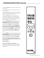
Master 475 Electronic Programmable Control
Manual Cooking
1. Press SET key – TEMP LED will light.
2. Set temperature using the dial (factory preset at 350°F).
3. Press SET key – FAN LED will light.
4. Select fan mode using one of the three (3) fan keys
(HIGH, LOW, PULSE) – the selected FAN LED will light.
5. Press SET key – TIME LED will light.
6. Set cook time using the dial (factory preset at 30:00).
7. Press SET key – ready to cook.
8. Press START/CANCEL to begin manual cooking.
Manual cooking using Cook-N-Hold
1. Press the COOK/HOLD key, that key’s LED will light.
2. Press SET key – TEMP LED will light.
3. Set cook temperature using the dial (factory preset at
350°F).
4. Press Set key – HOLD LED will light.
5. Set hold temperature using the dial (factory preset at
200°F).
6. Press SET key – FAN LED will light.
7. Select fan mode using one of the three (3) fan keys
(HIGH, LOW, PULSE) – the selected FAN LED will light.
8. Press SET key – TIME LED will light.
9. Set cook time using the dial (factory preset at 30:00).
10. Press SET key – ready to cook
11. Press START/CANCEL to begin manual cooking.
Programming Product Keys (Master )
Note: Cooking time(s) is the element of the program that
tells the controller that other information (temperature, fan
speed, etc.) will be inputted into the controller. The rst step
is to enter all the time periods required, followed by the
addition of the other cooking elements.
OPERATING INSTRUCTIONS Continued

Part Number 1955203 rev 4 4/15 15
1. Press and hold PROG key for three (3) seconds – all the
product key LEDS light.
2. Code will be displayed. The controller is asking for the
access code. Press 4-2-7-5 and the
START/CANCEL key. PROD will be displayed indicating
you have gained access to Product Programming.
3. Press the product key (1-9) into which you want to store
a cooking program. SHLF will be displayed. The control
is asking if you want to program the key as a shelf timer
or with a cooking pro le. Select your answer by pressing
the START/CANCEL key. When the correct answer is
displayed press the SET key. The TIME LED will light.
30:00 will be displayed.
4. Set rst cook time using dial. If more than one cooking
pro le is desired:
• Press the product key where the program is to be
stored (1-9) – PR-2 will be displayed.
• Set the second cook time using the dial (factory
presets for PR-2 through PR-5 are :00).
• Press the same product key (1-9 again – PR-3 will be
displayed.
• Repeat the process for all pro les. When the last
pro le time has been entered, press the SET key OR
If less than ve (5) pro les are desired press the SET key after
the last required pro le – PRE will be displayed, followed
by :00. The controller is asking if you would like a reminder
alarm (pre-alarm) to sound during the cooking process
(factory preset is :00).
5. If a pre-alarm signal is desired – dial in the time that
the alarm is to sound. (Ex. If the product is to be turned
halfway through the 60 minute cooking cycle, set the
pre-alarm to 30 minutes. If pre-alarm is not desired verify
that “:00” is displayed. Press the SET key – TEMP LED will
light, and the display will show the rst pro le cooking
temperature (factory preset to 350°F).
6 Set the rst cooking temperature using the dial.
• Press the product key – PR-2 will be displayed
followed by the second temperature.
• Set the second cooking temperature using the dial.
• Repeat as you did for cooking time, for all the
pro les desired.
OPERATING INSTRUCTIONS Continued
NOTE: the controller will only accept cooking temperatures
for the number of pro les for which a cooking time has been
set. If the product key is pressed after the last programmed
pro le, the rst temperature will be displayed.
• Press SET after the last cooking temperatures has
been entered, HOLD will be displayed.
7. Use the START/CANCEl key to select yes or no. Press the
SET key.
8. If yes was selected, the HOLD LED will light. Enter the
hold temperature using the dial. (factory preset at 200°F)
Press the SET key, FAN will be displayed and the FAN LED
will light.
• Set the fan speed desired for the rst cooking pro le
using the individual fan keys (HIGH, LOW or PULSE),
press the product key and set the fan speed for the
second cooking pro le. Continue until all the pro les
have been assigned a fan speed. Press the SET key
when complete. As with the temperature, if the
product key is pressed after the last programmed
pro le, the rst fan speed will be displayed.
9. FL or ST will be displayed (for ex time or straight time)
(factory preset for ex time). Select ex or straight time
using the START/CANCEL key for the rst pro le. Press
the product key and select straight time or ex time for
the second pro le. Continue until all the pro les have
been assigned straight or ex time. Press the SET key
when complete. If the product key is pressed after the last
programmed pro le, the rst pro le will be displayed.
10 Programming for that product key is complete.
Cooking Using The Product Keys
(Master )
1. On initial start-up, press the product key for the menu
item to be cooked. Wait until Load is displayed.
2. Load the oven.
3. Press the product key for the loaded menu item.
4. Press the START/CANCEL, key.
5. To cancel the alarm or the holding operation, press the
START/CANCEL key followed by the product key.

Part Number 1955203 rev 4 4/1516
Verifying Hold Time (Master )
While a product is being held, press and hold the product
key. The actual hold time will be displayed.
Selecting Fahrenheit or Celsius (Master 475)
Press PROG and ACTUAL TEMP keys at the same time, F or C
will be displayed. (Factory preset for F)
Press the START/CANCEL key to switch between F and C.
When the desired setting is displayed press the PROG and
ACTUAL TEMP keys at the same time.
Cooking With The Shelf Timer (Master )
The shelf timer option is used to independently time each of
the up to six di erent shelves or racks within the oven.
NOTE: To use the shelf timer option, at least one product key
must be programmed with a cooking pro le (temperature,
time, fan speed, ex or straight time). The program key
must be limited to a single cooking pro le to be used with
the shelf timing option. If more than one product key is to
be used, all product keys to be used must feature the same
cooking temperature and fan speed. Flex or straight time and
cooking time can be di erent. The Cook-N-Hold option can
not be used with the shelf timer.
Pressing the desired product key will bring the oven to the
desired cooking temperature, once the oven has reached
the proper cooking temperature as indicated by Load in the
display.
1. Press the product key containing the desired cooking
pro le (1-9).
2. Press the shelf key for the shelf location to be timed (1-6).
NOTE: product keys and shelf keys are the same keys.
3. Press the START/CANCEL key to begin the cooking/
timing process.
4. When the cooking/timing process is complete for each
shelf, an audible “done” signal will sound and the display
will indicate which shelf is nished. Example: SH-1
5. To turn o the alarm press the product key with the
ashing LED.
OPERATING INSTRUCTIONS Continued
EXAMPLE: Two product pro les contain the same cooking
temperature, fan speed and are both programmed for ex
time – keys 1 and 6.
Two trays of product are going to be cooked in the oven at
the same time. The rst tray will use product key 1 and will
be placed in rack position 2. The second tray will use product
key 6 and will be placed in rack position 4. Once the oven
display indicates LOAD:
1. Load food product into oven on shelf 2.
2. Press product key 1, then shelf key 2.
3. Press the START/CANCEL key to start cooking on shelf 2.
4. Load food product into oven on shelf 4.
5. Press product key 6, then shelf key 4.
6. Press the START/CANCEL key to start cooking on shelf 4.
7. When product on shelf 2 is nished cooking, an audible
alarm will sound and the display will ash DONE, then
SH-2 and the product key 1 LED will be ashing.
8. To turn o the alarm, press product key 1.
9. When the product on shelf 4 is nished cooking, an
audible alarm will sound and the display will ash DONE,
then SH-4 and the product key 6 LED will be ashing.
10. To turn o the alarm, press product key 6.

Part Number 1955203 rev 4 4/15 17
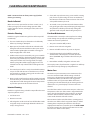
1. Preheat oven thoroughly (approx. 20 minutes) before use.
2. As a general rule, temperature should be reduced 25°
to 50° from that used in a standard/convection oven.
Cooking time may also be shorter, so we suggest closely
checking the rst batch of each product prepared.
3. Use the chart of suggested times and temperatures as
a guide. These will vary depending upon such factors
as size of load, temperature, and mixture of product
(particularly moisture) and density of product.
4. Keep a record of the times, temperature, and load sizes
you establish for various products. Once you have
determined these, they will be similar for succeeding
loads.
5. When practical, start cooking the lowest temperature
product rst and gradually work up to higher
temperatures.
6. If you nd that your previous temperature setting is more
than 10° higher than needed for succeeding loads, COOL
DOWN to reach the desired temperature before setting a
new cooking temperature.
7. When loading oven, work as quickly as possible to
prevent loss of heat.
8. Oven will continue to heat even though the timer goes
o . Product should be removed from the oven as soon as
possible to avoid over cooking.
9. Center pans on racks and load each shelf evenly to allow
for proper air circulation within the cavity.
10. When baking, weigh or measure the product in each pan
to assure even cooking.
11. When cooking six pans, use rack positions 1, 4, 6,8,10 and
12, starting from the top.
12. Do not overload the oven. Six pans are suggested for
most items, i.e., cakes, cookies, rolls, etc. However, the
maximum (13 pans) may be used for sh sticks, chicken
nuggets and hamburgers. Cooking times will have to be
adjusted.
13. Mu n pans should be placed in the oven back to front
or with the short side of the pans facing the front. This
results in the most evenly baked product.
14. When re-thermalizing frozen casseroles, preheat the oven
100° over the suggested temperature. Return to cooking
temperature when the oven is loaded. This will help
compensate for the introduction of a large frozen mass
into the cavity.
15. Use pan extenders or two inch deep 18” x 26” pans for
batter type products which weigh more than eight
pounds, i.e., Pineapple Upside down Cake.
16. Never place anything directly on the bottom of the oven
cavity. This obstructs the air ow and will cause uneven
results.
17. Never operate the oven if any of the exterior covers are
removed. These covers are necessary for protection
against exposure to live electrical parts and should
only be removed when the oven is being serviced by a
quali ed service personnel.
18. This is a commercial cooking oven not intended for non
commercial cooking installations or non food products.
19. Use appropriate food pans and trays for ovens.
20. Use oven mitts when adding or removing trays/pans from
oven when oven is operational.
21. Use care when removing product from the oven to
prevent spills which could cause serious inquiry to bare
skin and eyes. Higher rack levels on ovens are at eye level.
22. Exterior oven exteriors will become hot during operation
caution should be observed.
23. Proper weight handling and distribution of product in
tray or pan will prevent sudden shifts in product to avoid
spills and inquiry.
24. Do not operate ovens blower fan guard has been
removed.
25. Oven operation sound pressure level should not exceed
70 dB(A).
Note: Moisture will escape around the doors when baking
products with heavy moisture content, such as chicken,
potatoes, etc. This is normal.
PERFORMANCE RECOMMENDATIONS AND GENERAL SAFETY
PRECAUTIONS

Part Number 1955203 rev 4 4/1518
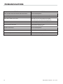
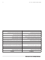
PROBLEM/SOLUTIONS
Problem Solution
Cakes are dark on the sides and not done in the center Lower oven temperature
Cakes edges are too brown Reduce number of pans or lower oven temperature
Cakes have light outer color Raise temperature
Cake settles slightly in the center Bake longer or raise oven temperature slightly.
Do not open doors too often or for long periods
Cake ripples Overloading pans or batter is too thin
Cakes are too coarse Lower oven Temperature
Pies have uneven color pans Reduce number of pies per rack
or eliminate use of bake pans
Cupcakes crack on top Lower oven temperature
Meats are browned and not done in center Lower temperature and roast longer.
Meats are well done and browned Reduce time. Limit amount of moisture
Meats develop hard crust Reduce temperature or place pan of water in oven.
Rolls have uneven color Reduce number or size of pans.

Part Number 1955203 rev 4 4/15 19
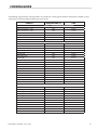
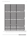
COOKING GUIDE
The following suggested times and temperatures are provided as a starting guide. Elevation, atmospheric conditions, recipe,
cooking pans and oven loading may a ect your actual results.
PRODUCT TEMPERATURE (ºF) TIME
Cakes
White Sheet Cakes – 5 lbs 300º 20 min
White Sheet Cakes – 6 lbs 300º 22 min
Yellow Sheet Cake – 5 lbs 325º 15 min
Chocolate Layer Cake – 21 oz 300º 22 min
Angel Food Cake 375º 22 min
Brownies 350º 15 min
Breads
Soda Biscuits 400º 6 min
Yeast Rolls 325º 24 min
Sweet Bread 325º 24 min
Corn Bread 350º 22 min
Gingerbread 300º 24 min
Apple Turnovers 350º 25 min
Cream Pu s 300º 25 min
Sugar Cookies 325º 12 min
Chocolate Chip cookies 375º 8 min
Apple Pie (Fresh) 375º 25 min
Blueberry Pie (Fresh) 350º 30 min
Blueberry Pie (Frozen) 300º 50 min
Pumpkin Pie (Frozen) 300º 50 min
Frozen Pizza 300º 6 min
Macaroni & Cheese 350º 15 min
Fish Sticks 350º 16 min
Stu ed Peppers 350º 45 min
Baked Potatoes 350º 60 min
Meats
Chick Parts 350º 45 min
Hamburger Patties-10/lb frozen 350º 8 min
Hamburger Patties - 10/lb fresh 350º 5 min
Hamburger Patties - 4/lb frozen 350º 12 min
Hamburger Patties – 4/lb fresh 350º 8 min
Meatloaf – 4lb 325º 45 min
Bacon 350º 10 min
Roast Beef 20lb 325º 3 hr 15 min
Prime Rib 10lb 300º 1 hr 45 min
Stu ed Port chops 350º 45 min
Lamb chops 375º 40 min
Boneless Veal Roast 300º 3 Hr

Part Number 1955203 rev 4 4/1520
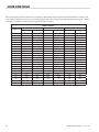
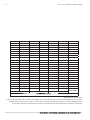
COOK AND HOLD
Please refer to the operating instructions to program the 450 and 455 control units for Cook and Hold feature. The times and
temperatures listed below are to be used as a starting guide. Your actual results may vary greatly depending on your elevation,
atmospheric conditions and other items being cooked at the same time.
Time in Hours
Weight in lbs
Temperature: 200ºF Temperature: 250ºF Temperature: 300ºF
Rare Medium Rare Medium Rare Medium
8 2.5 3.5 1.5 2 1.25 1.5
9 2.75 3.75 1.75 2.25 1.25 1.75
10 3 4.25 2 2.5 1.5 1.75
11 3.25 4.5 2 2.75 1.5 1.75
12 3.5 5 2.25 3 1.5 2
13 3.75 5 2.5 3.25 1.5 2.25
14 4 5.75 2.5 3.5 1.75 2.5
15 4.25 6 2.75 3.5 2 2.5
16 4.5 6.25 2.75 3.75 2 2.75
17 4.75 6.5 3 4 2.25 2.75
18 4.75 6.75 3.25 4.25 2.25 3
19 5 7.25 3.25 4.25 2.25 3
20 5.25 7.5 3.5 4.5 2.5 3.25
21 5.5 7.75 3.5 4.75 2.75 3.5
22 5.75 7.75 3.5 4.75 2.75 3.5
23 6 8.25 3.75 5 2.75 3.75
24 6 8.75 3.75 5 2.75 3.75
25 6.25 9 4.25 5.5 3 4
26 6.5 9.25 4.25 5.5 3.25 4.25
27 6.75 9.5 4.25 5.75 3.25 4.25
28 7 9.75 4.5 6 3.25 4.25
29 7.25 10 4.75 6.25 3.5 4.5
30 7.25 10.25 4.75 6.25 3.5 4.5
La page est en cours de chargement...
La page est en cours de chargement...
La page est en cours de chargement...
La page est en cours de chargement...
La page est en cours de chargement...
La page est en cours de chargement...
La page est en cours de chargement...
La page est en cours de chargement...
La page est en cours de chargement...
La page est en cours de chargement...
La page est en cours de chargement...
La page est en cours de chargement...
La page est en cours de chargement...
La page est en cours de chargement...
La page est en cours de chargement...
La page est en cours de chargement...
La page est en cours de chargement...
La page est en cours de chargement...
La page est en cours de chargement...
La page est en cours de chargement...
La page est en cours de chargement...
La page est en cours de chargement...
La page est en cours de chargement...
La page est en cours de chargement...
La page est en cours de chargement...
La page est en cours de chargement...
La page est en cours de chargement...
La page est en cours de chargement...
-
 1
1
-
 2
2
-
 3
3
-
 4
4
-
 5
5
-
 6
6
-
 7
7
-
 8
8
-
 9
9
-
 10
10
-
 11
11
-
 12
12
-
 13
13
-
 14
14
-
 15
15
-
 16
16
-
 17
17
-
 18
18
-
 19
19
-
 20
20
-
 21
21
-
 22
22
-
 23
23
-
 24
24
-
 25
25
-
 26
26
-
 27
27
-
 28
28
-
 29
29
-
 30
30
-
 31
31
-
 32
32
-
 33
33
-
 34
34
-
 35
35
-
 36
36
-
 37
37
-
 38
38
-
 39
39
-
 40
40
-
 41
41
-
 42
42
-
 43
43
-
 44
44
-
 45
45
-
 46
46
-
 47
47
-
 48
48


Garland GI-BH/IN 2500 Owner Instruction Manual
- Catégorie
- Cuisinières
- Taper
- Owner Instruction Manual
dans d''autres langues
- English: Garland GI-BH/IN 2500
Documents connexes
-
Garland E20 Series Owner Instruction Manual
-
Garland Master series Owner Instruction Manual
-
Garland Convection Microwave Oven Manuel utilisateur
-
-
-
-
-
-
-