Kozyheat Bellingham 52 Le manuel du propriétaire
- Catégorie
- Cheminées
- Taper
- Le manuel du propriétaire
Ce manuel convient également à

HUSSONG MANUFACTURING CO., INC.
READ ALL THESE STEPS
BEFORE STARTING INSTALLATION.
LEAVE THESE INSTRUCTIONS WITH THE
APPLIANCE.
This kit must be installed by a qualied installer,
service agency, or gas supplier at the time of
the heater installation. These instructions must
be used in conjunction with the installation and
operation manual provided with the appliance.
Please read the appliance owner’s manual
completely before performing any procedures in
these instructions.
INSTALLER: Leave this manual with the appliance.
CONSUMER: Retain this manual for future reference.
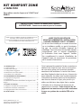
KOMFORT ZONE KIT
#KZK-1510
For use with replaces #CLW-72 and #BHM-52
This optional convection duct kit redistributes the
warm air ow away from the replace opening to
a more desirable location using natural convection
without the use of a fan. The warm air ow may be
relocated to a position higher up the wall, out the
sidewalls, or even to an adjacent room. The result
is much cooler wall temperatures above the re-
place opening for locating televisions, artwork, etc.
The use of this kit will permit lower mantel clear-
ances to be used. These lower mantel clear-
ances must be only used when the KZK Duct
system is installed.
English and French installation manuals are available through your
local dealer. Visit our website www.kozyheat.com.
Les manuels d’installation en français et en anglais sont disponibles
chez votre détaillant local. Visitez
www.kozyheat.com
.
Hussong Manufacturing Co., Inc.
P.O. Box 577, 204 Industrial Park Drive
Lakeeld, MN 56150-0577, USA Rev. 4, 5/20
1.0 INTRODUCTION .......................................................................3
1.1 Kit Contents..........................................................................................3
1.2 Fireplace Preparation ........................................................................3
1.3 Suggested Congurations .............................................................. 4
1.4 Dimensions and Overview .............................................................6
1.5 Air Duct Pipe Run ...............................................................................8
2.0 FRAMING AND CLEARANCES ................................................9
2.1 Clearance to Sprinkler ...................................................................... 9
2.2 Framing................................................................................................10
2.3 Minimum Shelf Requirements ....................................................12
3.0 FACING AND FINISHING .......................................................14
3.1 Non-combustible Requirements ................................................ 14
3.2 Combustible Finish .......................................................................... 16
3.3 Hearth and Mantel Clearances ....................................................19
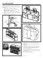
4.0 INSTALLATION .......................................................................21


Komfort Zone Kit #KZK-1510 R.4 Hussong Mfg. Co., Inc. • Kozy Heat Fireplaces 3
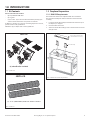
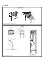
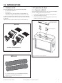
1.1 Kit Contents
ALL kit contents must be installed.
• (2) 15" plenum kit: KZK-1510
• (2) air grilles
• (12) 6" collars - (6) to attach to the bottom of the plenum; (6) to
attach to the unit where the cover plates are removed
(1) KZK-610 is used for a 10' vent run. If installing beyond 10' vent run,
you will need to order (1) KZK-CPL6.
KZK-CPL6 is (6) 6" couplers that connect (2) KZK-610
1.0 INTRODUCTION
#KZK-1510
(6) take o collars included
(6) - 10’ x 6” (aluminum ex) listed to UL-181Class 0 Air Duct
#KZK-610
Figure 1.1, #KZK-1510
Figure 1.2, #KZK-610
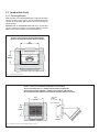
1.2 Fireplace Preparation
1.2.1 BHM-52 Requirements
The header heat shield is not required for KZK-1510 installation.
The stand-o assembly still must be installed. To install stand-o
assembly,
1. Locate the stand-o assembly and header heat shield on top of
the replace, as shipped.
2. Discard header heat shield.
3. Attach the stand-o assembly pieces as shown below and secure
with (4) screws.
Figure 1.3, BHM-52 Stand-o Assembly Installation
Remove and discard header heat
shield for Komfort Zone Kits only
Stand-o assembly

4 Hussong Mfg. Co., Inc. • Kozy Heat Fireplaces Komfort Zone Kit #KZK-1510 R.4
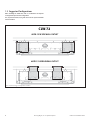
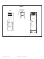
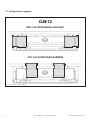
1.3 Suggested Congurations
When installing the #KZK-1510, take in consideration the replace
venting and the plenum tube conguration.
The (2) plenums and the (2) air grilles in this kit are required and both
must be installed.
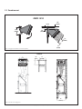
Figure 1.4, #KZK-1510 Suggested Congurations for CLW-72
#KZK-1510 SIDE WALL OUTLET
#KZK-1510 REAR WALL OUTLET
CLW-72

Komfort Zone Kit #KZK-1510 R.4 Hussong Mfg. Co., Inc. • Kozy Heat Fireplaces 5
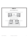
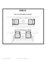
Figure 1.5, #KZK-1510 Suggested Congurations for BHM-52
#KZK-1510 SIDE WALL OUTLET
#KZK-1510 REAR WALL OUTLET
BHM-52

6 Hussong Mfg. Co., Inc. • Kozy Heat Fireplaces Komfort Zone Kit #KZK-1510 R.4
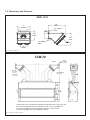
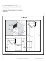
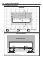
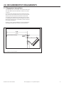
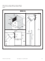
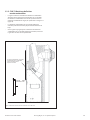
1.4 Dimensions and Overview
3½”
(89mm)
26
½” (673mm)
20’ (6m)
12
½”
(317mm)
18
½”
(469mm)
9
¾”
(247mm)
40
¾”
(1035mm)
CEILING
MINIMUM
CLEARANCE
TO CEILING
MIN
MAX
Minimum
1½” (38mm)
clearance to
combustibles
around pipe
The tubing that connects the plenum to the replace must be UL181 Class 0 approved air duct.
If you are mounting the plenum above the replace 10’ (3m) or less, use (1) #KZK-610 kit.
If you are mounting the plenum above the replace between 10’ (3m) to 20’ (6m)
you will need (2) #KZK-610 kit and (1) #KZK-CPL6 coupler kit.
CLW-72
Figure 1.6, KZK-1510 Dimensions
Figure 1.7, KZK-1510 Overview for CLW-72
15”
(381mm)
10
⁄”
(258mm)
7
⁄”
(193mm)
5
⁄”
(149mm)
19
½”
(495mm)
2
½”
(63mm)
13
⁄”
(300mm)
6”
(152mm)
1
¾”
(44mm)
STANDOFF
STANDOFF
#KZK-1510

Komfort Zone Kit #KZK-1510 R.4 Hussong Mfg. Co., Inc. • Kozy Heat Fireplaces 7
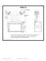
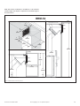
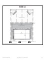
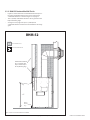
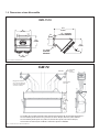
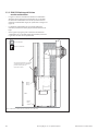
Figure 1.8, KZK-1510 Overview for BHM-52
3½”
(89mm)
43
¼” (1099mm) MIN
20’ (6m) MAX
7
¾”
(197mm)
41
¼”
(1047mm)
31”
(787mm)
2
½”
(63mm)
The tubing that connects the plenum to the replace must be UL181 Class 0 approved air duct.
If you are mounting the plenum above the replace 10’ (3m) or less, use (1) #KZK-610 kit.
If you are mounting the plenum above the replace between 10’ (3m) to 20’ (6m)
you will need (2) #KZK-610 kit and (1) #KZK-CPL6 coupler kit.
CEILING
MINIMUM
CLEARANCE
TO CEILING
BHM-52
Minimum
1/2” (12mm)
clearance to
combustibles
around pipe

8 Hussong Mfg. Co., Inc. • Kozy Heat Fireplaces Komfort Zone Kit #KZK-1510 R.4
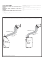
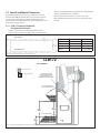
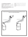
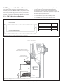
1.5 Air Duct Pipe Run
IMPORTANT: The air duct pipe cannot run horizontally without a
vertical rise.
IMPORTANT: The clearance around the air duct pipes must be
maintained.
Use #KZK-610 UL181 Class 0 Air Duct piping to connect the plenum(s)
to the unit.
Hussong Mfg. requires pipes to be listed as UL181 Class 0 Air Duct to
connect the plenum(s) to the unit.
IMPORTANT: The specied clearance around the air duct pipes must
be maintained for each unit.
CLW-72: 1-1/2" (38mm) around the air duct pipes. See Figure 1.7 on
page 6.
BHM-52: 1/2" (12mm) around the air duct pipes. See Figure 1.8 on
page 7.
Figure 1.9, Minimum Vent Pipe Run - only (1) plenum shown
WHEN INSTALLING AIR DUCT PIPE MAINTAIN A MINIMUM 4" VERTICAL RISE FOR EVERY 12" HORIZONTAL RUN
MINIMUM BEND RADIUS=6” (152mm)
12”
(304mm)
4” (101mm)
12”
(304mm)
4” (101mm)
MINIMUM BEND RADIUS=6” (152mm)
CLW-72 BHM-52

Komfort Zone Kit #KZK-1510 R.4 Hussong Mfg. Co., Inc. • Kozy Heat Fireplaces 9
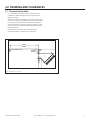
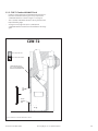
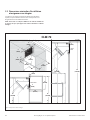
2.0 FRAMING AND CLEARANCES
Figure 2.1, KZK Clearance to Sprinkler
2.1 Clearance to Sprinkler
• In a situation where a sprinkler head is installed within the
proximity to a #KZK discharge opening, the diagram below
MUST be followed.
• The distance between a sprinkler head and discharge opening
cannot be less than 60" (1524mm) in length at every point from
the origin of the discharge opening. You must also verify the
sprinkler head sensor is set to the proper heat setting so it does
not activate when the room heats up from the replace being
operated normally.
• Please follow local building codes to determine what
temperature setting is relevant for your installation.
CEILING SPRINKLER HEAD
60” MIN
(1524mm)
3
½” MIN
(89mm)

10 Hussong Mfg. Co., Inc. • Kozy Heat Fireplaces Komfort Zone Kit #KZK-1510 R.4
17”
(431mm)
10
¼”
(260mm)
67
¼”
(1708mm)
10¼”
(260mm)
17”
(431mm)
22”
(558mm)
CLW-72
Plenum rough opening
Height and Width
Minimum depth of replace enclosure
Unit and plenum
side view
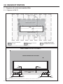
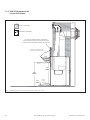
2.2 Framing
Figure 2.2, Minimum Clearances from Air Discharge to Ceiling
Figure 2.3, CLW-72 Rough Opening and Framing
10¼”
(260mm)
3
½”
(89mm)
½”
(13mm)
2
½”
(64mm)
½”
(13mm)
CEILING
#KZK-1510

Komfort Zone Kit #KZK-1510 R.4 Hussong Mfg. Co., Inc. • Kozy Heat Fireplaces 11
10¼”
(260mm)
17”
(431mm)
76
¼”
(1937mm)
28
¾”
(730mm)
10
¼”
(260mm)
17”
(431mm)
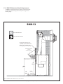
BHM-52
Plenum rough opening
Height and Width
Minimum depth of replace enclosure
Unit and plenum
side view
Figure 2.4, BHM-52 Rough Opening and Framing

12 Hussong Mfg. Co., Inc. • Kozy Heat Fireplaces Komfort Zone Kit #KZK-1510 R.4
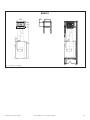
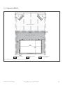
2.3 Minimum Shelf Requirements
The drawings in this section show the framing requirements if you
desire the air discharge opening to be located within the bump-out
or bookshelf framing.
NOTE: Take careful consideration in the dierence of the minimum
chamber height of the replace compared to the minimum height of
the shelf enclosure.
2”
(51mm)
18”
(457mm)
79”
(2007mm)
81”
(2057mm)
3”
(76mm)
3”
(76mm)
18”
(457mm)
18”
(457mm)
79”
(2007mm)
81”
(2057mm)
3”
(76mm)
3”
(76mm)
18”
(457mm)
18”
(457mm)
3”
(76mm)
ENCLOSURE FLOOR
GRILLE
ENCLOSURE TOP (front view)
CEILING
ENCLOSURE FLOOR
GRILLE
CLW-72
Figure 2.5, CLW-72 Minimum Shelf Requirements

Komfort Zone Kit #KZK-1510 R.4 Hussong Mfg. Co., Inc. • Kozy Heat Fireplaces 13
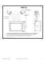
Figure 2.6, BHM-52 Minimum Shelf Requirements
2”
(51mm)
18”
(457mm)
88”
(2235mm)
90”
(2286mm)
3”
(76mm)
3”
(76mm)
18”
(457mm)
18”
(457mm)
88”
(2235mm)
90”
(2286mm)
3”
(76mm)
3”
(76mm)
18”
(457mm)
18”
(457mm)
3”
(76mm)
ENCLOSURE FLOOR
GRILLE
ENCLOSURE TOP (front view)
CEILING
ENCLOSURE FLOOR
GRILLE
BHM-52
NOTE: Take careful consideration in the dierence of the minimum
chamber height of the replace compared to the minimum height of
the shelf enclosure.

14 Hussong Mfg. Co., Inc. • Kozy Heat Fireplaces Komfort Zone Kit #KZK-1510 R.4
3.0 FACING AND FINISHING
3.1 Non-combustible Requirements
COMBUSTIBLE MATERIAL ALLOWEDNON-COMBUSTIBLE MATERIAL ONLY
COMBUSTIBLE MATERIAL ALLOWED
SEE IMAGE BELOW FOR
ACCEPTABLE SCREW LOCATIONS
COMBUSTIBLE MATERIAL ALLOWED
NON-COMBUSTIBLE MATERIAL ONLY
LOWER COVER PANEL
COMBUSTIBLE MATERIAL ALLOWED
39⁄”
(1006mm)
75
⁄”
(1915mm)
18
⁄”
(465mm)
10
½”
(267mm)
6
⁄”
(161mm)
21
⁄”
(538mm)
13”
(330mm)
3
¾
”
(95mm)
9
¾
”
(248mm)
1
½
”
(38mm)
3
¾
”
(95mm)
13”
(330mm)
NON-COMBUSTIBLE MATERIAL ONLY
COMBUSTIBLE MATERIAL ALLOWED
NO SCREWS ALLOWED
NO SCREWS ALLOWED
NO SCREWS ALLOWED
SCREW PATTERN LOCATIONS
Figure 3.1, CLW-72 Minimum Non-combustible Finishing Dimensions
Figure 3.2, CLW-72 Minimum Non-combustible Finishing Dimensions Screw Locations
CLW-72

Komfort Zone Kit #KZK-1510 R.4 Hussong Mfg. Co., Inc. • Kozy Heat Fireplaces 15
49⁄”
(1261mm)
1
½”
(38mm)
8
⁄”
(205mm)
2
½”
(64mm)
52
½”
(1333mm)
33
½”
(851mm)
68
⁄”
(1743mm)
Non-combustible material only
Combustible material allowed
Combustible Material Allowed
Combustible material allowedNon-combustible material only
Combustible material allowed
No screws allowed
Figure 3.3, BHM-52 Minimum Non-combustible Finishing Dimensions
BHM-52

16 Hussong Mfg. Co., Inc. • Kozy Heat Fireplaces Komfort Zone Kit #KZK-1510 R.4
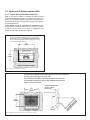
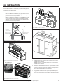
3.2 Combustible Finish
3.2.1 Finishing Material
NOTE: If you desire to run nishing material up to edge of the discharge
opening, see Figure 3.4 and Figure 3.5 below. Finishing material must
not block the air discharge grille and must be run evenly along the
plenum opening.
WARNING! RISK OF OVERHEATING AND FIRE! Ensure the KZK duct
system is installed in accordance to this manual AND the convection
bae is removed when using these combustible clearances.
Figure 3.4, #KZK-1510 Drywall Finish
157⁄8”
(403mm)
11
7⁄8”
(301mm)
11
7⁄8”
(301mm)
COMBUSTBILE
MATERIAL
UP TO 1” THICK
DISCHARGE GRILLE
UP TO 1” (25mm) THICK COMBUSTIBLE MATERIAL UP TO EDGE OF
THE AIR DISCHARGE GRILLE. 1” COMBUSTIBLE MATTERIAL CANNOT GO
CLOSER TO DISCHARGE OPENING. 1” COMBUSTIBLE MATERIAL GOES ON TOP
OF ANY REQUIRED NON-COMBUSTIBLE MATERIAL REQUIRED ON THE FIREPLACE
Figure 3.5, #KZK-1510 Combustible Finishing Material up to 1" Thick
15”
(381mm)
10
¼”
(260mm)
DRYWALL STOPS AT EDGE OF AIR DISCHARGE OPENING.
AIR GRILLE DISCHARGE WILL OVERLAP EDGES OF DRYWALL

Komfort Zone Kit #KZK-1510 R.4 Hussong Mfg. Co., Inc. • Kozy Heat Fireplaces 17
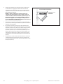
3.2.2 CLW-72 Combustible Wall Finish
• Figure 3.6 shows installation of combustible wall nish up to 1"
thick. This combustible material goes on any required non-
combustible materials as shown in Figure 3.1 on page 14.
• This 1" (25mm) combustible material is able to go down to the
replace nishing edge.
• See Figure 3.4 on page 16 for up to 1" (25mm) thick
combustible material installation around the KZK air discharge
grille.
Figure 3.6, KZK-1510 Combustible Wall Finish for CLW-72
COMBUSTIBLE WALL FINISH
UP TO 1” (25mm) THICK MAY BE
INSTALLED OVER CEMENT BOARD
TOP
FINISHING
EDGE
FIREPLACE ENCLOSURE FLOOR
NON-COMBUSTIBLE ZONE
NON-COMBUSTIBLE MATERIAL
BOTTOM
FINISHING
EDGE
CLW-72

18 Hussong Mfg. Co., Inc. • Kozy Heat Fireplaces Komfort Zone Kit #KZK-1510 R.4
3.2.3 BHM-52 Combustible Wall Finish
• Figure 3.6 shows installation of combustible wall nish up to 1"
thick. This combustible material goes on any required non-
combustible materials as shown in Figure 3.3 on page 15.
• This 1" (25mm) combustible material is able to go down to the
replace nishing edge.
• See Figure 3.4 on page 16 for up to 1" (25mm) thick
combustible material installation around the KZK air discharge
grille.
Figure 3.7, KZK-1510 Combustible Wall Finish for BHM-52
Top nishing
edge
Bottom
nishing
edge
Combustible wall nish
up to 1” (25mm) thick
may be installed up to
the top nishing edge
Non-combustible zone
Non-combustible material
BHM-52

Komfort Zone Kit #KZK-1510 R.4 Hussong Mfg. Co., Inc. • Kozy Heat Fireplaces 19
3.3 Hearth and Mantel Clearances
The following drawings show the hearth and mantel clearances
allowed for the BHM-52 and CLW-72 with no surround or optional
surrounds installed (if applicable). Follow the drawings for the
minimum distance needed between the hearth and mantel to allow
for proper servicing clearances.
3.3.1 CLW-72 Finishing Guidelines
for Optional Surrounds
• Figure 3.8 shows where to end nishing materials, when
measuring from the nishing edge, to allow installation of any
optional surround. Most nishing material will not t behind the
optional surround(s) when it is installed.
• Measurement 'A' shows the space to leave on each side.
• Measurement 'B' shows the space to leave on the top and the
bottom.
9
½
”
(248mm)
28
⁄
”
(715mm)
18
⁄
”
(467mm)
12” (305mm)
9” (229mm)
6” (152mm)
14” (356mm)
17” (432mm)
20” (508mm)
COMBUSTIBLE WALL FINISH
MAY BE INSTALLED OVER CEMENT
BOARD AND BUTT UP TO THE
FINISHING EDGE AROUND THE OPENING
EACH SQUARE REPRESENTS 1”
(25mm) OF MANTEL PROJECTION
TOPFINISHING EDGE
BOTTOM FINISHING EDGE
NO SURROUND
NON-COMBUSTIBLE ZONE
NON-COMBUSTIBLE MATERIAL
Figure 3.8, CLW-72 Finishing Guidelines for Optional Surrounds
Figure 3.9, CLW-72 Hearth and Mantel Clearances for No Surround
B
A
FINISHING TRIM EDGE
SURROUND EDGE
Surround A B
CW72-RS 1-1/2" (38mm) 1-1/2" (38mm)
CW72-RS4 2-5/8" (66mm) 2-5/8" (66mm)
CW72-GS 6" (152mm) 2-1/2" (64mm)
CW72-FS 3-1/8" (79mm) 3-1/8" (79mm)
CLW-72

20 Hussong Mfg. Co., Inc. • Kozy Heat Fireplaces Komfort Zone Kit #KZK-1510 R.4
3.3.2 BHM-52 Mantel and Hearth Requirements
• The BHM-52 is equipped only with a safety screen that ts inside
the nishing edge. Finishing material may butt up against the
nishing edge.
31”
(786mm)
2
½”
(64mm)
33
½”
(850mm)
12” (305mm)
9” (229mm)
6” (152mm)
14” (356mm)
Combustible wall nish up to
1” (25mm) may be installed over
cement board and butt up to the
nishing edge around opening
Each square represents
1” (25mm)
of mantel projection
Combustible oor
Non-combustible zone
Non-combustible material
Top nishing edge
Bottom
nishing
edge
Figure 3.10, BHM-52 Hearth and Mantel Clearances for No Surround
BHM-52
La page est en cours de chargement...
La page est en cours de chargement...
La page est en cours de chargement...
La page est en cours de chargement...
La page est en cours de chargement...
La page est en cours de chargement...
La page est en cours de chargement...
La page est en cours de chargement...
La page est en cours de chargement...
La page est en cours de chargement...
La page est en cours de chargement...
La page est en cours de chargement...
La page est en cours de chargement...
La page est en cours de chargement...
La page est en cours de chargement...
La page est en cours de chargement...
La page est en cours de chargement...
La page est en cours de chargement...
La page est en cours de chargement...
La page est en cours de chargement...
La page est en cours de chargement...
La page est en cours de chargement...
La page est en cours de chargement...
La page est en cours de chargement...
La page est en cours de chargement...
La page est en cours de chargement...
-
 1
1
-
 2
2
-
 3
3
-
 4
4
-
 5
5
-
 6
6
-
 7
7
-
 8
8
-
 9
9
-
 10
10
-
 11
11
-
 12
12
-
 13
13
-
 14
14
-
 15
15
-
 16
16
-
 17
17
-
 18
18
-
 19
19
-
 20
20
-
 21
21
-
 22
22
-
 23
23
-
 24
24
-
 25
25
-
 26
26
-
 27
27
-
 28
28
-
 29
29
-
 30
30
-
 31
31
-
 32
32
-
 33
33
-
 34
34
-
 35
35
-
 36
36
-
 37
37
-
 38
38
-
 39
39
-
 40
40
-
 41
41
-
 42
42
-
 43
43
-
 44
44
-
 45
45
-
 46
46


Kozyheat Bellingham 52 Le manuel du propriétaire
- Catégorie
- Cheminées
- Taper
- Le manuel du propriétaire
- Ce manuel convient également à
dans d''autres langues
Documents connexes
-
Kozyheat Bellingham 52 Le manuel du propriétaire
-
-
kozy heat Bellingham 44 Le manuel du propriétaire
-
-
-
-
-
-
-
