
75.5366.07 UL MAGLOCKS 20171130 Page 1 of 475.5366.07 UL MAGLOCKS 20171130 Page 1 of 475.5366.07 UL MAGLOCKS 20171130 Page 1 of 4
UL MAGLOCKS
USER’S GUIDE
ELECTROMAGNETIC LOCKS
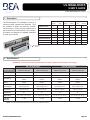
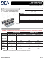
The Electromagnetic Lock (Maglock) series is a
surface-mounted, magnetic-lock assembly. They
are available in single- and dual-lock varieties,
various sizes (i.e. force), and also avaible with or
without built-in Door Status Switch (“DS” versions).
All models are designed for standard installation
on most types of doors.
Door Position
Switch
ENGLISH
door conguration holding force door status sensor
single dual 600 lb 1200 lb with without
10MAGLOCK1UL
10MAGLOCK1ULDS
10MAGLOCK3UL
10MAGLOCK3ULDS
10MAGLOCK5UL
10MAGLOCK5ULDS
10MAGLOCK6UL
10MAGLOCK6ULDS
1 Description
600 LB MAGLOCKS 1200 LB MAGLOCKS
DESCRIPTION
10MAGLOCK3UL
10MAGLOCK3ULDS
10MAGLOCK6UL
10MAGLOCK6ULDS
10MAGLOCK1UL
10MAGLOCK1ULDS
10MAGLOCK5UL
10MAGLOCK5ULDS
Lock: single double single double
Input Voltage: 12 or 24 VDC 12 or 24 VDC 12 or 24 VDC 12 or 24 VDC
Relay Rating:
1.0 A @ 24 VDC
resistive
1.0 A @ 24 VDC
resistive
1.0 A @ 24 VDC
resistive
1.0 A @ 24 VDC
resistive
Reed Switch
Rating:
SPDT 0.5 amp @ 30 VAC/VDC
resistive
SPDT 0.5 amp @ 30 VAC/VDC
resistive
SPDT 0.5 amp @ 30 VAC/VDC
resistive
SPDT 0.5 amp @ 30 VAC/VDC
resistive
Power
Consumption:
505 mA @ 12 VDC /
260 mA @ 24 VDC
505*2 mA @ 12 VDC /
260*2 mA @ 24 VDC
505 mA @ 12 VDC /
260 mA @ 24 VDC
505*2 mA @ 12 VDC /
260*2 mA @ 24 VDC
Dimensions:
9.84 x 1.65 x 1.02 in
250 x 42 x 26 mm
19.76 x 1.65 x 1.02 in
502 x 42 x 26 mm
10.47 x 2.87 x 1.58 in
266 x 73 x 40 mm
20.94 x 2.87 x 1.58 in
532 x 73 x 40 mm
Certication: UL UL UL UL
Operating
Temperature:
14 – 131 °F (-10 – 55 °C) 14 – 131 °F (-10 – 55 °C) 14 – 131 °F (-10 – 55 °C) 14 – 131 °F (-10 – 55 °C)
Operating
Humidity:
0 – 95% 0 – 95% 0 – 95% 0 – 95%
ATTENTION: This product must be powered from a UL-listed, regulated, power-limited, power supply!
NOTE: The specications listed above are for an indoor, dry, installation location.
2 Specications

Page 2 of 4 75.5366.07 UL MAGLOCKS 20171130Page 2 of 4 75.5366.07 UL MAGLOCKS 20171130
FOLD ON DOTTED LINE
(1/8")
DRILL 3.2mm HOLE
(2 PLACES)
PLACE AGAINST DOOR
(11/16")
DRILL 16mm HOLE
TEMPLATE
PLACE AGAINST JAMB
OPPOSITE HINGES FOR
L.H.R. DOOR INSTALLATION
PLACE AGAINST HEADER
185mm ARMATURE PLATE GUIDE PIN HOLE
[6mm(1/4") DIA, 12.5mm(1/2") DEEP]
185mm ARMATURE PLATE
[6mm(1/4") DIA, 12.5mm(1/2") DEEP]
PLACE AGAINST JAMB
OPPOSITE HINGES FOR
R.H.R. DOOR INSTALLATION
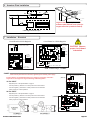
STEP 1
FOLD TEMPLATE ALONG DOTTED LINE.
PLACE TEMPLATE AGAINST DOOR AND HEAD FRAME.
DRILL HOLES AS INDICATED ON TEMPLATE.
STEP 2
MOUNT THE ARMATURE PLATE TO DOOR USING
1 RUBBER WASHER SANDWICHED BETWEEN 2 STEEL
WASHER (THE RUBBER WASHER AND 2 STEEL
WASHER ARE INSTALLED ON THE THROUGH SEXNUT
BETWEEN THE ARMATURE PLATE AND DOOR).
●
●
●
●
STEP 3
DETACH MOUNTING PLATE FROM MAGNET BY REMOVING
2 SOCKET CAP SCREWS. SCREWS COULD BE ACCESSED
THROUGH BOTTOM OF MAGNET.
●
●
INSTALL THE MOUNTING PLATE WITH 2 FLAT HEAD
SCREWS (THE 2 M5x15 FLAT HEAD SCREWS ARE
INSTALLED IN THE SLOTTED HOLES FOR ADJUSTMENT).
ADJUST MOUNTING PLATE SO THAT IT FORMS A RIGHT
ANGLE WITH THE ARMATURE PLATE.
●
●
USING THE MOUNTING PLATE AS A TEMPLATE,DRILL
THE WIRE HOLE.
●
DRILL AND INSTALL THE REMAINING MOUNTING SCREWS.
STEP 4
INSTALL MAGNET TO MOUNTING PLATE WITH
2 M6 SCREWS SUPPLIED.
●
INSTALL ELECTRICAL WIRING PER
INSTRUCTION SHEET.
●
STEP 5
TEST ALL FUNCTIONS OF THIS MODEL (SEE
WIRING INSTRUCTION).
●
STEP 6
INSERT 2 LOCKING STOPPERS IN TWO END
PLATES,AND COVER WITH 4 mm SCREWS.
●
STEP 7
INSERT 2 ALUMINUM CAPS TO COVER THE
TWO M6 SCREW HOLES.
●
STEP 8
NOTE: IF NEEDED, USE SMALL MAGNET TO
REMOVE LOCKING STOPPERS FROM HOLES.
●
DWG. NO. 820001
Page 2 of 4 75.5366.07 UL MAGLOCKS 20171130
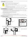
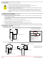
5 Handle the equipment with care. Damaging the mating surfaces of the magnet and armature plate may reduce locking efciency.
5 The maglock mounts rigidly to the door frame. The armature plate mounts to the door with the hardware provided. This allows
the armature plate to pivot about its center to compensate for door wear and misalignment.
5 Template use must take place with the door in its normally closed position.
5 Add threadlocker to all screws before installing, and rmly tighten screws.
5 Install only for indoor, dry applications.
5 Installation and wiring must be performed in compliance with ANSI/NFPA70 regulations.
5 The Maglock shall be installed within the same room as other equipment and circuitry connecting to the Maglock (per UL 864).
5 Shut off all power going to header before attempting any wiring procedures.
5 Maintain a clean and safe environment when working in public areas.
5 Constantly be aware of pedestrian trafc around the door area.
5 Always stop pedestrian trafc through the doorway when performing tests that may result in unexpected reactions
by the door.
5 Always check placement of all wiring before powering up to ensure that moving door parts will not catch any wires
and cause damage to equipment or cable insulation.
5 Ensure compliance with all applicable safety standards (i.e. ANSI A156.10) upon completion of installation.
DO NOT over-tighten the armature plate.
The rubber washer is designed to allow the armature plate to automatically adjust position for best mating position between the magnet and armature plate.
DOOR FRAME
DOOR FRAME
DOOR FRAME
MAGNET
MAGNET
MAGNET
DOOR
DOOR
DOOR
MOUNTING PLATE
Use the applicable mounting template.
See image of template below.
See User’s Guide 75.5643 for U-bracket
installation (to be used with glass doors).
MOUNTING PLATE
L&Z BRACKET
FILLER
ARMATURE PLATE
ARMATURE PLATE
ARMATURE PLATE
Filler L&Z bracket
3 Precautions
4 Installation Notes
5 Installation – Mechanical
Mounting Options
TYPICAL INSTALLATION

75.5366.07 UL MAGLOCKS 20171130 Page 3 of 475.5366.07 UL MAGLOCKS 20171130 Page 3 of 4
Page 2 of 2 75.5366.02 20140401
5 Installation - Mechanical & Electrical
LOCK STATUS SWITCH (SPDT)
POWER
SUPPLY
+ -
POWER
SELECTOR
JUMPER
LED
MAG BOND SENSOR
MAGNET
TIMER (0-90 SEC)
TYPICAL INSTALLATION
NOTE: DO NOT over-tighten the armature plate. The rubber washer is designed to allow the armature
plate to automatically adjust position for best mating position between the lock and armature plate.
DOOR FRAME
ARMATURE PLATE
MAGNET
ANGLE
BRACKET
MOUNTING
PLATE
MOUNTING
PLATE
STRINGER
HOLE FOR
GUIDE PIN
HOLE FOR NUT
RUBBER WASHER
STEEL WASHER
ARMATURE PLATE
SCREW M8 (35MM)
GUIDE PIN
DOOR
NUT
SPACER
WASHER
ARMATURE
PLATE
DOOR
NUT
DOOR FRAME
DOOR FRAME
DOOR
ARMATURE PLATE
ARMATURE PLATE
MAGNET
MAGNET
DOOR DOOR
MOUNTING
PLATE
CAUTION: Observe proper
circuit board orientation!
NOTE: The product must be powered from a UL listed, regulated, power limited, power supply.
NOTE: If power switch is not wired between DC source voltage and magnet,
it will take a longer time to de-energize the magnet simulating residual magnetism.
1. 12 VDC INPUT
A. Required power 0.5A (Max).
B. Connect ground (-) lead from a 12 VDC power source to Terminal 2.
C. Connect positive (+) lead from a 12 VDC power source to Terminal 1.
D. Check jumper for 12 VDC operation.
2. 24 VDC INPUT
A. Required power 0.25A (Max).
B. Connect ground (-) lead from a 24 VDC power source to Terminal 2.
C. Connect positive (+) lead from a 24 VDC power source to Terminal 1.
D. Check jumper for 24 VDC operation.
3. CONTACTS
1. Relay dry contacts are rated 1A at 24 VDC for safe operation, DO NOT exceed this
rating.
2. If a NO switch is required, connect the wires from the system to Terminal 4 & Terminal 3.
3. If a NC switch is required, connect the wires from the system to Terminal 4 & Terminal 5.
DS VERSION
24/7 Tech Support: 1-800-407-4545 | Customer Service: 1-800-523-2462 | General Tech Questions: T[email protected] | Tech Docs: www.beasensors.com
75.5366.07 UL MAGLOCKS 20171130 Page 3 of 4
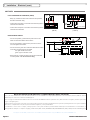
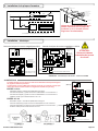
Circuit Board for 600 lb Maglocks
NOTE: Terminals ratings: 12~24AWG
Circuit Board for 1200 lb Maglocks
7 Installation – Electrical
CAUTION! Observe
proper circuit board
orientation!
+ -
G
1 2 3 4 5
+ - NO C NC
12VDC
24VDC
POWER
SELECTOR
JUMPER
0 - 90 SEC.
RELOCK TIMER
POWER
SUPPLY
+ -
LOCK STATUS RELAY (SPDT)
G
R B G
R
G
B
W
1 2 3 4 5
+ - NO C NC
12VDC
24VDC
POWER
SELECTOR
JUMPER
0 - 90 SEC.
RELOCK TIMER
POWER
SUPPLY
LOCK STATUS RELAY (SPDT)
Align the black, plastic piece of the
armature plate with the cover plate (i.e.
magnet must line up with the switch).
6 Armature Plate Installation
1
PCB
2
MAGNETIC LOCK
sw
+
-
NC
RED
GREEN
BLACK
LIGHT
COM
REED SWITCH
ON
DOOR STATUS SENSOR SWITCH*
* Switch changes state when door is open
NO
1
PCB
2
MAGNETIC LOCK
NC
RED
GREEN
BLACK
LIGHT
COM
REED SWITCH
ON
DOOR STATUS SENSOR SWITCH*
* Switch changes state when door is open
NO
Hole For Guide Pin
Hole For Nut
Rubber Washer
Steel Washer
Armature Plate
Nut
Spacer
Door
Screw M8 35mm
Guide Pin
The product must be powered from a UL-listed, regulated, power-limited, power supply.
If power switch is not wired between DC source voltage(+) and magnet, it will take a
longer time to de-energize the magnet simulating residual magnetism.
12 VDC INPUT
- Required power: See Specications on page 2.
- Connect positive (+) lead from a 12 VDC power source to Terminal 1.
- Connect negative (-) lead from a 12 VDC power source to Terminal 2.
- Check jumper for 12 VDC operation.
24 VDC INPUT
- Required power: See Specications on page 2.
- Connect positive (+) lead from a 24 VDC power source to Terminal 1.
- Connect negative (-) lead from a 24 VDC power source to Terminal 2.
- Check jumper for 24 VDC operation.
(600 lb)
(1200 lb)
G
R B G
R
G
B
W
1 2 3 4 5
+ - NO C NC
12VDC
24VDC
POWER
SELECTOR
JUMPER
0 - 90 SEC.
RELOCK TIMER
POWER
SUPPLY
LOCK STATUS RELAY (SPDT)
+ -
G
1 2 3 4 5
+ - NO C NC
12VDC
24VDC
POWER
SELECTOR
JUMPER
0 - 90 SEC.
RELOCK TIMER
POWER
SUPPLY
+ -
LOCK STATUS RELAY (SPDT)
POWER

Page 4 of 4 75.5366.07 UL MAGLOCKS 20171130Page 4 of 4 75.5366.07 UL MAGLOCKS 20171130
Tech Support: 1-800-407-4545 | Customer Service: 1-800-523-2462 | General Tech Questions: T[email protected] | Tech Docs: www.BEAinc.com
Page 4 of 4 75.5366.07 UL MAGLOCKS 20171130
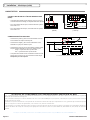
LOCK STATUS RELAY CONTACTS (SPDT)
- Relay dry contacts are rated 1A at 24 VDC for safe operation,
DO NOT exceed this rating.
- If a NO switch is required, connect the wires from the system to
Terminal 3 and Terminal 4.
- If a NC switch is required, connect the wires from the system to
Terminal 4 and Terminal 5.
DOOR STATUS SWITCH
- Connect the positive (+) lead from the power source to the
black wire of the Door Status Sensor switch.
- Connect the negative (-) lead from the power source to one
end of the light for door status.
- Connect the red or green wire of the Door Status Sensor switch
to the other end of the light for door status.
red = light off with door closed
green = light on with door closed
- Reed switch dry contacts are rated 0.25 amp at 30 VAC/VDC
for safe operation. Do not exceed this rating.
7 Installation – Electrical (cont.)
(600 lb) (1200 lb)
G
R B G
R
G
B
W
1 2 3 4 5
+ - NO C NC
12VDC
24VDC
POWER
SELECTOR
JUMPER
0 - 90 SEC.
RELOCK TIMER
POWER
SUPPLY
LOCK STATUS RELAY (SPDT)
SWITCHES
+ -
G
1 2 3 4 5
+ - NO C NC
12VDC
24VDC
POWER
SELECTOR
JUMPER
0 - 90 SEC.
RELOCK TIMER
POWER
SUPPLY
+ -
LOCK STATUS RELAY (SPDT)
1
PCB
2
MAGNETIC LOCK
sw
+
-
NC
RED
GREEN
BLACK
LIGHT
COM
REED SWITCH
ON
DOOR STATUS SENSOR SWITCH*
* Switch changes state when door is open
NO
1
PCB
2
MAGNETIC LOCK
NC
RED
GREEN
BLACK
LIGHT
COM
REED SWITCH
ON
DOOR STATUS SENSOR SWITCH*
* Switch changes state when door is open
NO
BEA Inc., the sensor manufacturer, cannot be held responsible for incorrect installations or inappropriate adjustments or the sensor/device; therefore, BEA Inc. does not
guarantee any use of the sensor outside its intended purpose.
BEA Inc. strongly recommends that installation and service technicians be AAADM-certifi ed for pedestrian doors, IDA-certifi ed for doors/gates, and factory-trained for
the type of door/gate system.
Installers and service personnel are responsible for executing a risk assessment following each installation/service performed, ensuring that the sensor system installation
and/or device is compliant with local, national, and international regulations, codes, and standards.
Once installation or service work is complete, a safety inspection of the system should be performed and documented per the manufacturers recommendations, or
industry guidelines. Examples of compliance may apply to ANSI 156.10, ANSI 156.19, ANSI/DASMA 102, ANSI/DASMA 107, UL325, UL294, International Building Code.
BEA INSTALLATION/SERVICE COMPLIANCE EXPECTATIONS

75.5366.07 UL MAGLOCKS 20171130 Page 1 of 475.5366.07 UL MAGLOCKS 20171130 Page 1 of 4
UL MAGLOCKS
GUIDE D’UTILISATION
VERROUS ÉLECTROMAGNÉTIQUES
La série de verrous électromagnétiques (Maglock)
est un ensemble de verrous magnétiques montés
en surface. Ils sont offerts en variétés de verrous
simples et doubles, de diverses tailles (c’est-à-dire
force) et aussi offerts avec ou sans commutateur
intégré d’état de porte (versions « DS »). Tous les
modèles sont conçus pour une installation standard
sur la plupart des types de portes.
Commutateur
de position de
porte
FRANÇAIS
conguration de porte
force de rétention
capteur d’état de porte
simple double
600 lb
(272 kg)
1200 lb
(544 kg)
avec sans
10MAGLOCK1UL
10MAGLOCK1ULDS
10MAGLOCK3UL
10MAGLOCK3ULDS
10MAGLOCK5UL
10MAGLOCK5ULDS
10MAGLOCK6UL
10MAGLOCK6ULDS
1 Description
MAGLOCKS 600 LB MAGLOCKS 1 200 LB
DESCRIPTION
10 MAGLOCK3UL
10MAGLOCK3ULDS
10 MAGLOCK6UL
10MAGLOCK6ULDS
10 MAGLOCK1UL
10MAGLOCK1ULDS
10 MAGLOCK5UL
10MAGLOCK5ULDS
Verrou : simple double simple double
Tension d’entrée : 12 ou 24 V CC 12 ou 24 V CC 12 ou 24 V CC 12 ou 24 V CC
Calibre du relais :
1 A sous 24 V CC
résistif
1 A sous 24 V CC
résistif
1 A sous 24 V CC
résistif
1 A sous 24 V CC
résistif
Calibre du
commutateur à lames :
SPDT 0,5 A sous 30 V CA/V CC
résistif
SPDT 0,5 A sous 30 V CA/V CC
résistif
SPDT 0,5 A sous 30 V CA/V CC
résistif
SPDT 0,5 A sous 30 V CA/V CC
résistif
Consommation
d’énergie :
505 mA sous 12 V CC /
260 mA sous 24 V CC
505*2 mA sous 12 V CC /
260*2 mA sous 24 V CC
505 mA sous 12 V CC /
260 mA sous 24 V CC
505*2 mA sous 12 V CC /
260*2 mA sous 24 V CC
Dimension :
9,84 x 1,65 x 1,02 po
250 x 42 x 26 mm
19,76 x 1,65 x 1,02 po
502 x 42 x 26 mm
10,47 x 2,87 x 1,58 po
266 x 73 x 40 mm
20,94 x 2,87 x 1,58 po
532 x 73 x 40 mm
Certication : UL UL UL UL
Température de
fonctionnement :
14 – 131 °F (-10 – 55 °C) 14 – 131 °F (-10 – 55 °C) 14 – 131 °F (-10 – 55 °C) 14 – 131 °F (-10 – 55 °C)
Humidité en
fonctionnement :
0 – 95 % 0 – 95 % 0 – 95 % 0 – 95 %
ATTENTION : Ce produit doit être activé à l’aide d’une alimentation électrique homologuée UL, régulée et limitée en puissance!
REMARQUE : Les spécications listées ci-dessus sont pour un emplacement d’installation intérieur et sec.
2 Spécications

Page 2 of 4 75.5366.07 UL MAGLOCKS 20171130Page 2 of 4 75.5366.07 UL MAGLOCKS 20171130
FOLD ON DOTTED LINE
(1/8")
DRILL 3.2mm HOLE
(2 PLACES)
PLACE AGAINST DOOR
(11/16")
DRILL 16mm HOLE
TEMPLATE
PLACE AGAINST JAMB
OPPOSITE HINGES FOR
L.H.R. DOOR INSTALLATION
PLACE AGAINST HEADER
185mm ARMATURE PLATE GUIDE PIN HOLE
[6mm(1/4") DIA, 12.5mm(1/2") DEEP]
185mm ARMATURE PLATE
[6mm(1/4") DIA, 12.5mm(1/2") DEEP]
PLACE AGAINST JAMB
OPPOSITE HINGES FOR
R.H.R. DOOR INSTALLATION
STEP 1
FOLD TEMPLATE ALONG DOTTED LINE.
PLACE TEMPLATE AGAINST DOOR AND HEAD FRAME.
DRILL HOLES AS INDICATED ON TEMPLATE.
STEP 2
MOUNT THE ARMATURE PLATE TO DOOR USING
1 RUBBER WASHER SANDWICHED BETWEEN 2 STEEL
WASHER (THE RUBBER WASHER AND 2 STEEL
WASHER ARE INSTALLED ON THE THROUGH SEXNUT
BETWEEN THE ARMATURE PLATE AND DOOR).
●
●
●
●
STEP 3
DETACH MOUNTING PLATE FROM MAGNET BY REMOVING
2 SOCKET CAP SCREWS. SCREWS COULD BE ACCESSED
THROUGH BOTTOM OF MAGNET.
●
●
INSTALL THE MOUNTING PLATE WITH 2 FLAT HEAD
SCREWS (THE 2 M5x15 FLAT HEAD SCREWS ARE
INSTALLED IN THE SLOTTED HOLES FOR ADJUSTMENT).
ADJUST MOUNTING PLATE SO THAT IT FORMS A RIGHT
ANGLE WITH THE ARMATURE PLATE.
●
●
USING THE MOUNTING PLATE AS A TEMPLATE,DRILL
THE WIRE HOLE.
●
DRILL AND INSTALL THE REMAINING MOUNTING SCREWS.
STEP 4
INSTALL MAGNET TO MOUNTING PLATE WITH
2 M6 SCREWS SUPPLIED.
●
INSTALL ELECTRICAL WIRING PER
INSTRUCTION SHEET.
●
STEP 5
TEST ALL FUNCTIONS OF THIS MODEL (SEE
WIRING INSTRUCTION).
●
STEP 6
INSERT 2 LOCKING STOPPERS IN TWO END
PLATES,AND COVER WITH 4 mm SCREWS.
●
STEP 7
INSERT 2 ALUMINUM CAPS TO COVER THE
TWO M6 SCREW HOLES.
●
STEP 8
NOTE: IF NEEDED, USE SMALL MAGNET TO
REMOVE LOCKING STOPPERS FROM HOLES.
●
DWG. NO. 820001
5 Manipulez soigneusement l’équipement. Endommager les surfaces de contact de l’élément et de la plaque d’armature pourrait
réduire l’efcacité du verrouillage.
5 Le verrou magnétique se monte de manière rigide sur le cadre de la porte. La plaque d’armature se monte sur la porte à l'aide de
la quincaillerie fournie. Cela permet à la plaque d’armature de pivoter autour de son centre pour compenser l’usure et le mauvais
alignement de la porte.
5 Un gabarit doit être utilisé avec la porte en position normalement fermée.
5 Ajoutez de l'adhésif frein-let à toutes les vis avant l’installation et serrez fermement les vis.
5 À installer seulement pour des applications intérieures sèches.
5 L’installation et le câblage doivent être effectués conformément aux règlements ANSI/NFPA70.
5 Le verrou magnétique doit être installé dans la même pièce que l’autre équipement et circuit connecté au verrou (selon UL 864).
5 Coupez l’alimentation de la tête avant d’effectuer un câblage, quel qu’il soit.
5 Maintenez un environnement propre et sécurisé lorsque vous travaillez dans des endroits publics.
5 Soyez toujours vigilant du passage de piétons dans les environs de la porte.
5 Arrêtez toujours toute la circulation piétonne par l’ouverture de la porte lorsque vous effectuez des tests qui peuvent
entraîner des activations inattendues de la porte.
5 Vériez toujours la position de tout câblage avant d’établir le courant an de vous assurer que les pièces en mouvement
de la porte n’accrochent pas de ls, ce qui pourrait causer des dommages matériels ou à l’isolation des câbles.
5 Assurez-vous que tout est conforme aux normes de sécurité applicables (par ex. : ANSI A156.10) une fois l’installation
terminée.
Ne serrez PAS trop la plaque d’armature.
La rondelle en caoutchouc est conçue pour permettre la plaque d’armature de s’ajuster automatiquement à la meilleure position de contact entre l’aimant et la plaque d’armature.
CADRE DE LA
PORTE
CADRE DE LA
PORTE
CADRE DE LA
PORTE
AIMANT
AIMANT
AIMANT
PORTE
PORTE
PORTE
PLAQUE DE MONTAGE
Utilisez le gabarit de montage applicable.
Consultez l’image du gabarit ci-dessous.
Consultez le guide d'utilisation 75.5643
pour l’installation d’un support en U (à
utiliser avec des portes en verre).
PLAQUE DE MONTAGE
SUPPORT L&Z
REMPLISSAGE
PLAQUE D’ARMATURE
PLAQUE D’ARMATURE
PLAQUE D’ARMATURE
Remplissage Support L&Z
3 Précautions
4 Remarques sur l’installation
5 Installation – mécanique
Options de montage
INSTALLATION TYPE

75.5366.07 UL MAGLOCKS 20171130 Page 3 of 475.5366.07 UL MAGLOCKS 20171130 Page 3 of 4
Page 2 of 2 75.5366.02 20140401
5 Installation - Mechanical & Electrical
LOCK STATUS SWITCH (SPDT)
POWER
SUPPLY
+ -
POWER
SELECTOR
JUMPER
LED
MAG BOND SENSOR
MAGNET
TIMER (0-90 SEC)
TYPICAL INSTALLATION
NOTE: DO NOT over-tighten the armature plate. The rubber washer is designed to allow the armature
plate to automatically adjust position for best mating position between the lock and armature plate.
DOOR FRAME
ARMATURE PLATE
MAGNET
ANGLE
BRACKET
MOUNTING
PLATE
MOUNTING
PLATE
STRINGER
HOLE FOR
GUIDE PIN
HOLE FOR NUT
RUBBER WASHER
STEEL WASHER
ARMATURE PLATE
SCREW M8 (35MM)
GUIDE PIN
DOOR
NUT
SPACER
WASHER
ARMATURE
PLATE
DOOR
NUT
DOOR FRAME
DOOR FRAME
DOOR
ARMATURE PLATE
ARMATURE PLATE
MAGNET
MAGNET
DOOR DOOR
MOUNTING
PLATE
CAUTION: Observe proper
circuit board orientation!
NOTE: The product must be powered from a UL listed, regulated, power limited, power supply.
NOTE: If power switch is not wired between DC source voltage and magnet,
it will take a longer time to de-energize the magnet simulating residual magnetism.
1. 12 VDC INPUT
A. Required power 0.5A (Max).
B. Connect ground (-) lead from a 12 VDC power source to Terminal 2.
C. Connect positive (+) lead from a 12 VDC power source to Terminal 1.
D. Check jumper for 12 VDC operation.
2. 24 VDC INPUT
A. Required power 0.25A (Max).
B. Connect ground (-) lead from a 24 VDC power source to Terminal 2.
C. Connect positive (+) lead from a 24 VDC power source to Terminal 1.
D. Check jumper for 24 VDC operation.
3. CONTACTS
1. Relay dry contacts are rated 1A at 24 VDC for safe operation, DO NOT exceed this
rating.
2. If a NO switch is required, connect the wires from the system to Terminal 4 & Terminal 3.
3. If a NC switch is required, connect the wires from the system to Terminal 4 & Terminal 5.
DS VERSION
24/7 Tech Support: 1-800-407-4545 | Customer Service: 1-800-523-2462 | General Tech Questions: T[email protected] | Tech Docs: www.beasensors.com
Carte de circuit pour les verrous magnétiques 600 lb
REMARQUE : Caractéristiques des bornes : Calibre 12~24 AWG
Carte de circuit pour les verrous magnétiques 1 200 lb
7 Installation – électrique
ATTENTION :
Observez la bonne
orientation de la carte
de circuit!
+ -
G
1 2 3 4 5
+ - NO F NF
12VCC
24VCC
CAVALIER DU
SÉLECTEUR
D’ALIMENTATION
MINUTERIE DU DOUBLE
VERROUILLAGE 0 à 90 S
ALIMEN-
TATION
+ -
RELAIS DE L’ÉTAT DE VERROUILLAGE
G
R B G
R
G
B
W
1 2 3 4 5
+ - NO C NC
12VCC
24 VCC
CAVALIER DU
SÉLECTEUR
D’ALIMENTATION
MINUTERIE DU
DOUBLE
VERROUILLAGE
0 à 90 S
ALIMEN-
TATION
RELAIS DE L’ÉTAT DE VERROUILLAGE
Alignez la pièce en plastique noir de la
plaque d’armature avec la plaque de
protection (c.-à-d., l’aimant doit être
aligné avec le commutateur).
6 Installation de la plaque d'armature
1
PCB
2
sw
+
-
NC
COM
ON
NO
1
PCB
2
VERROU MAGNÉTIQUE
NC
ROUGE
VERT
NOIR
VOYANT
COM
COMMUTATEUR À LAMES
ON
NO
*Le commutateur change l’état lorsque la porte est ouverte
COMMUTATEUR DU CAPTEUR D’ÉTAT DE PORTE*
Trou pour broche guide
Trou pour écrou
Rondelle en caoutchouc
Rondelle en acier
Plaque d’armature
Écrou
Accessoire d’espacement
Porte
Vis M8 35mm
Broche guide
Le produit doit être mis sous tension à l’aide d’une alimentation électrique homologuée
UL, régulée et limitée en puissance!
Si l’interrupteur n’est pas câblé entre la tension source CC (+) et l’aimant, le temps pour
mettre hors tension l’aimant simulant un magnétisme résiduel sera plus long.
ENTRÉE 12 V CC
- Alimentation requise Consultez les spécications à la page 2.
- Connectez le l positif (+) à partir d’une source d’alimentation 12 V CC à la borne 1.
- Connectez le l négatif (-) à partir d’une source d’alimentation 12 V CC à la borne 2.
- Vériez le cavalier pour le fonctionnement en 12 V CC.
ENTRÉE 24 V CC
- Alimentation requise : Consultez les spécications à la page 2.
- Connectez le l positif (+) à partir d’une source d’alimentation 24 V CC à la borne 1.
- Connectez le l négatif (-) à partir d’une source d’alimentation 24 V CC à la borne 2.
- Vériez le cavalier pour le fonctionnement en 24 V CC.
(600 lb)
(1 200 lb)
G
R B G
R
G
B
W
1 2 3 4 5
+ - NO C NC
12VCC
24 VCC
CAVALIER DU
SÉLECTEUR
D’ALIMENTATION
MINUTERIE DU
DOUBLE
VERROUILLAGE
0 à 90 S
ALIMEN
-
TATION
RELAIS DE L’ÉTAT DE VERROUILLAGE
+ -
G
1 2 3 4 5
+ - NO F NF
12VCC
24VCC
CAVALIER DU
SÉLECTEUR
D’ALIMENTATION
MINUTERIE DU DOUBLE
VERROUILLAGE 0 à 90 S
ALIMEN-
TATION
+ -
RELAIS DE L’ÉTAT DE VERROUILLAGE
ALIMENTATION

Page 4 of 4 75.5366.07 UL MAGLOCKS 20171130Page 4 of 4 75.5366.07 UL MAGLOCKS 20171130
Tech Support: 1-800-407-4545 | Customer Service: 1-800-523-2462 | General Tech Questions: T[email protected] | Tech Docs: www.BEAinc.com
CONTACT DES RELAIS DE L’ÉTAT DE VERROUILLAGE
(SPDT)
- La capacité des contacts secs du relais est 1 A à 24 V CC pour
un fonctionnement sans danger, ne dépassez PAS cette capacité.
- Si un commutateur NO est requis, connectez les ls du système
aux bornes 3 et 4.
- Si un commutateur NF est requis, connectez les ls du système
aux bornes 4 et 5.
COMMUTATEUR D’ÉTAT DE PORTE
- Connectez le l positif (+) de la source d’alimentation au l noir
du commutateur de capteur d’état de porte.
- Connectez le l négatif (-) de la source d’alimentation à une
extrémité du voyant pour l’état de la porte.
- Connectez le l rouge ou vert du commutateur du capteur d’état
de porte à l’autre extrémité du voyant pour l’état de la porte.
Rouge = voyant éteint avec la porte fermée
Vert = voyant allumé avec la porte fermée
- La capacité des contacts secs du commutateur à lames est 0,25
ampère à 30 V CA/V CC pour un fonctionnement sans danger.
Ne dépassez pas cette capacité.
7 Installation – électrique (suite)
(600 lb) (1 200 lb)
G
R B G
R
G
B
W
1 2 3 4 5
+ - NO C NC
12VCC
24 VCC
CAVALIER DU
SÉLECTEUR
D’ALIMENTATION
MINUTERIE DU
DOUBLE
VERROUILLAGE
0 à 90 S
ALIMEN-
TATION
RELAIS DE L’ÉTAT DE VERROUILLAGE
COMMUTATEURS
+ -
G
1 2 3 4 5
+ - NO F NF
12VCC
24VCC
CAVALIER DU
SÉLECTEUR
D’ALIMENTATION
MINUTERIE DU DOUBLE
VERROUILLAGE 0 à 90 S
ALIMEN-
TATION
+ -
RELAIS DE L’ÉTAT DE VERROUILLAGE
1
PCB
2
sw
+
-
NC
COM
ON
NO
1
PCB
2
VERROU MAGNÉTIQUE
NC
ROUGE
VERT
NOIR
VOYANT
COM
COMMUTATEUR À LAMES
ON
NO
*Le commutateur change l’état lorsque la porte est ouverte
COMMUTATEUR DU CAPTEUR D’ÉTAT DE PORTE*
BEA Inc., le fabricant du capteur, ne peut être tenu responsable des installations incorrectes ou des réglages inappropriés ou du capteur / appareil; par conséquent, BEA Inc. ne garantit pas
l’utilisation du capteur en dehors de son usage prévu.
BEA Inc. recommande fortement que les techniciens d’installation et de service soient certifi és AAADM pour les portes piétonnes, certifi és IDA pour les portes / portails et formés en usine pour
le type de système de portes / portails.
Les installateurs et le personnel de maintenance sont responsables de l’exécution d’une évaluation des risques après chaque installation / service, garantissant que l’installation du système de
capteur et / ou l’appareil sont conformes aux réglementations, codes et normes locales, nationales et internationales.
Une fois l’installation ou les travaux de maintenance terminés, une inspection de sécurité du système doit être effectuée et documentée conformément aux recommandations du fabricant ou
aux directives de l’industrie. Des exemples de conformité peuvent s’appliquer aux normes ANSI 156.10, ANSI 156.19, ANSI / DASMA 102, ANSI / DASMA 107, UL325, UL294, Code international
du bâtiment.
ATTENTES DE CONFORMITÉ DE L’INSTALLATION/L’ENTRETIEN DE BEA
-
 1
1
-
 2
2
-
 3
3
-
 4
4
-
 5
5
-
 6
6
-
 7
7
-
 8
8


dans d''autres langues
- English: BEA UL LISTED MAGLOCKS User guide
Documents connexes
Autres documents
-
Dwyer Series L4 Manuel utilisateur
-
-
Vortex VX 2400LP Series Manuel utilisateur
-
MINN KOTA PowerDrive Installation Instructions Manual
-
Miller Big Blue 602P Le manuel du propriétaire
-
Lincoln Electric SA-400I Mode d'emploi
-
SkyLink MC-201 Manuel utilisateur
-
Genie GCL Fire Door Operator / Installation Manual
-
Hach SC200 Basic User Manual
-