
1048
GAS DECK OVEN
INSTALLATION - OPERATION - MAINTENANCE
1048
FOURS À GAZ À PLATEFORME
MANUEL D'INSTALLATION - UTILISATION - ENTRETIEN
BLODGETT OVEN COMPANY
www.blodgett.com
44 Lakeside Avenue, Burlington, Vermont 05401 USA Telephone (800) 331Ć5842, (802) 860Ć3700 Fax: (802)864Ć0183
PN 18648 Rev G (12/09)
E 2009 - G.S. Blodgett Corporation

IMPORTANT
FOR YOUR SAFETY
Do not store or use gasoline or other flammable vapors or liquids in the vicinity
of this or any other appliance.
AVERTISSEMENT
Ne pas entreposer ni utiliser de l'essence ni d'autres vapeurs ou liquides inflamĆ
mables dans le voisinage de cet appariel, ni de tout autre appareil.
INSTRUCTIONS TO BE FOLLOWED IN THE EVENT THE USER SMELLS GAS
MUST BE POSTED IN A PROMINENT LOCATION. THIS INFORMATION MAY BE
OBTAINED BY CONTACTING YOUR LOCAL GAS SUPPLIER.
LES INSTRUCTIONS À RESPECTER AU CAS OÙ L'UTILISATEUR PERÇOIT UNE
ODEUR DE GAZ DOIVENT ÊTRE AFFICHÉES DANS UN ENDROIT BIEN VISIBLE.
VOUS POUVEZ VOUS LES PROCURER AUPRÈS DE VOTRE FOURNISSEUR DE
GAZ LOCAL.
WARNING: IMPROPER INSTALLATION, ADJUSTMENT, ALTERATION, SERVICE OR
MAINTENANCE CAN CAUSE PROPERTY DAMAGE, INJURY OR DEATH. READ THE
INSTALLATION, OPERATING AND MAINTENANCE INSTRUCTIONS THOROUGHLY
BEFORE INSTALLING OR SERVICING THIS EQUIPMENT
AVERTISSEMENT: UNE INSTALLATION, UN AJUSTEMENT, UNE ALTÉRATION, UN
SERVICE OU UN ENTRETIEN NON CONFORME AUX NORMES PEUT CAUSER DES
DOMMAGES À LA PROPRIÉTE, DES BLESSURES OU LA MORT. LISEZ ATTENTIVEĆ
MENT LES DIRECTIVES D'INSTALLATION, D'OPÉRATION ET D'ENTRETIEN AVANT
DE FAIRE L'INSTALLATION OU L'ENTRETIEN DE CET ÉQUIPEMENT.
The information contained in this manual is important for the proper installation,
use, and maintenance of this oven. Adherence to these procedures and instrucĆ
tions will result in satisfactory baking results and long, trouble free service.
Please read this manual carefully and retain it for future reference.
Les informations données dans le présent manuel sont importantes pour installer,
utiliser et entretenir correctement ce four. Le respect de ces instructions et procéĆ
dures permettra d'obtenir de bons résultats de cuisson et une longue durée de serĆ
vice sans problèmes. Veuillez lire le présent manuel et le conserver pour pouvoir
vous y reporter à l'avenir.
Errors: Descriptive, typographic or pictorial errors are subject to correction. SpecificaĆ
tions are subject to change without notice.
Erreurs:Les erreurs de description, de typographie ou d'illustration font l'objet de
corrections. Les caractéristiques sont sujettes à modifications sans préavis.

THE REPUTATION YOU CAN COUNT ON
UNE RÉPUTATION SUR LAQUELLE VOUS POUVEZ COMPTER
For over a century and a half, The Blodgett Oven Company has been building
ovens and nothing but ovens. We've set the industry's quality standard for all
kinds of ovens for every foodservice operation regardless of size, application
or budget. In fact, no one offers more models, sizes, and oven applications
than Blodgett; gas and electric, fullĆsize, halfĆsize, countertop and deck, conĆ
vection, Cook'n Hold, CombiĆOvens and the industry's highest quality Pizza
Oven line. For more information on the full line of Blodgett ovens contact your
Blodgett representative.
Cela fait maintenant dessus un siècle et demi que Blodgett se spécialise dans
la fabrication de fours. Nous avons établi les normes de qualité qui s'appliĆ
quent dans l'industrie à tous les types de fours utilisés dans les services aliĆ
mentaires, quel qu'en soit la taille, l'exploitation ou le budget. En fait, ni n'offre
plus de modèles, de tailles et d'applications de fours que Blodgett. À gaz et
électriques. De tailles différentes, sur plan de travail et superposables. Qu'il
s'agisse de fours à convection, des modèles Cook'n Hold et CombiĆOven, ou
de la gamme de fours à pizzas de la plus haute qualité offerte sur le marché.
Pour de plus amples informations sur la gamme complète de fours Blodgett,
veuillez contacter votre représentant Blodgett.

Your Service Agency's Address:
Adresse de votre agence de service:
Model/Modèl:
Serial Number/Numéro de série:
Your oven was installed by/
Installateur de votre four:
Your oven's installation was checked by/
Contrôleur de l'installation de votre four:

Table of Contents/Table des Matières
level 1 component
level 2 component 2. . . . . . . . . . . . . . . . . . . .
level 3 component 7. . . . . . . . . . . . . . . . . . .
level 1 nc component

Table of Contents/Table des Matières
Introduction
Oven Description and Specifications 2. . . .
Oven Components 3. . . . . . . . . . . . . . . . . . . .
Installation
Delivery and Location 4. . . . . . . . . . . . . . . . .
Oven Assembly 5. . . . . . . . . . . . . . . . . . . . . .
Packaging 5. . . . . . . . . . . . . . . . . . . . . . . . . .
Leg Attachment 5. . . . . . . . . . . . . . . . . . . . .
caster attachment 5. . . . . . . . . . . . . . . . . . .
Double Section Assembly 6. . . . . . . . . . . .
3 Piece Deflector Assembly 6. . . . . . . . . . .
Ultra Rokite Shelves 6. . . . . . . . . . . . . . . . .
Deck Seal 7. . . . . . . . . . . . . . . . . . . . . . . . . .
Flue Plates 7. . . . . . . . . . . . . . . . . . . . . . . . .
Leveling the Oven 7. . . . . . . . . . . . . . . . . . .
Adjustments Associated with Initial
Installation 7. . . . . . . . . . . . . . . . . . . . . . . . .
Ventilation 8. . . . . . . . . . . . . . . . . . . . . . . . . . .
Canopy Type Exhaust Hood 8. . . . . . . . . .
Direct Flue Arrangement 9. . . . . . . . . . . . .
Venting Problems 9. . . . . . . . . . . . . . . . . . .
Utility Connections -
Standards and Codes 10. . . . . . . . . . . . . . . . .
Gas Connection 11. . . . . . . . . . . . . . . . . . . . . .
Operation
Safety Information 14. . . . . . . . . . . . . . . . . . . .
Oven Control 15. . . . . . . . . . . . . . . . . . . . . . . . .
General Guidelines for Operating
Personnel 16. . . . . . . . . . . . . . . . . . . . . . . . . . . .
Maintenance
Cleaning and Preventative Maintenance 17.
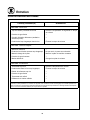
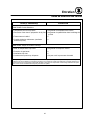
Troubleshooting Guide 18. . . . . . . . . . . . . . . .
Introduction
Description et Spécifications du Four 20. . . .
Éléments du Four 21. . . . . . . . . . . . . . . . . . . . .
Installation
Livraison et Implantation 22. . . . . . . . . . . . . . .
Montage du Four 23. . . . . . . . . . . . . . . . . . . . .
Emballage 23. . . . . . . . . . . . . . . . . . . . . . . . .
Assemblage des Pieds 23. . . . . . . . . . . . . . .
Fixation des Roulettes 23. . . . . . . . . . . . . . .
Montage de la Section Double 24. . . . . . . .
Montage du Déflecteur en Trois
Parties 24. . . . . . . . . . . . . . . . . . . . . . . . . . . . .
Des Plaques en Rokite 24. . . . . . . . . . . . . . .
Joint de Plaque 25. . . . . . . . . . . . . . . . . . . . .
Plaques de Cheminée 25. . . . . . . . . . . . . . .
Mise à Niveau des Fours 25. . . . . . . . . . . . .
Réglages à Faire Lors de
l'Installation Initiale 25. . . . . . . . . . . . . . . . . .
Ventilation 26. . . . . . . . . . . . . . . . . . . . . . . . . . .
Hotte D'évacuation Type Voûte 26. . . . . . .
En Prise Directe 27. . . . . . . . . . . . . . . . . . . . .
Problêmes de la Ventilation 27. . . . . . . . . . .
Branchements de Service - Normes et
Codes 28. . . . . . . . . . . . . . . . . . . . . . . . . . . . . . .
Branchement de Gaz 29. . . . . . . . . . . . . . . . .
Utilisation
Information de Sécurité 32. . . . . . . . . . . . . . . .
Les Commandes du Four 33. . . . . . . . . . . . . .
Consignes Générales à l'Intention des
Utilasateurs 34. . . . . . . . . . . . . . . . . . . . . . . . . .
Entretien
Nettoyage et Entretien Préventif 35. . . . . . . .
Guide de Détection des Pannes 36. . . . . . . .

Introduction
2
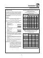
Oven Description and Specifications
Blodgett Deck ovens have set industry wide stanĆ
dards of excellence for baking characteristics,
performance and reliability. They remain unsurĆ
passed for product quality.
Simplicity of design and quality construction
throughout assure years of trouble free service
when the equipment is properly installed and
maintained.
Features include a full angle iron frame, all welded
radius corners and stainless steel fronts and
doors.
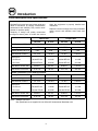
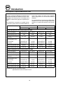
Natural Gas Propane Gas
US Units SI Units US Units SI Units
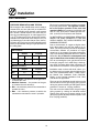
1048ĆB (85,000 BTU) GAS SPECIFICATIONS
Heating Value 1000 BTU/hr 37.3 MJ/m
3
2550 BTU/hr 95.0 MJ/m
3
Specific Gravity (air=1.0) 0.63 0.63 1.53 1.53
Gas Manifold Pressure 3.5" W.C. 0.87 kPa 10" W.C. 2.49 kPa
Oven Input
Per Burner
Per Oven
42,500 BTU/hr
85,000 BTU/Hr
12.4 kW
24.9 kW
42,500 BTU/Hr
85,000 BTU/Hr
12.4 kW
24.9 kW
Main Burner Orifice Size 30 MTD* 3.3 mm 48 MTD* 1.93 mm
Pilot Burner Orifice Size .018" Dia. .46 mm .010" Dia. .25 mm
1048ĆB (120,000 BTU) GAS SPECIFICATIONS
Heating Value 1000 BTU/hr 37.3 MJ/m
3
2550 BTU/hr 95.0 MJ/m
3
Specific Gravity (air=1.0) 0.63 0.63 1.53 1.53
Gas Manifold Pressure 3.5" W.C. 0.87 kPa 10" W.C. 2.49 kPa
Oven Input
Per Burner
Per Oven
60,000 BTU/hr
120,000 BTU/Hr
17.6 kW
35.2 kW
60,000 BTU/Hr
120,000 BTU/Hr
17.6 kW
35.2 kW
Main Burner Orifice Size 23 MTD* 3.9 mm 44 MTD* 2.18 mm
Pilot Burner Orifice Size .018" Dia. .46 mm .010" Dia. .25 mm
NOTE: *Multiple Twist Drill
Gas Specifications are supplied in both US and SI (International Standard) units.

Introduction
3
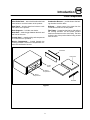
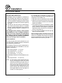
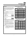
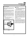
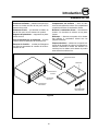
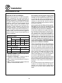
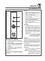
Oven Components
Ultra Rokite Deck - stone deck that absorbs heat
from below to cook the bottom of the product.
Steel Deck - absorbs heat from below to cook
the bottom of the product.
Deck Supports - hold the oven decks.
Deck Seal - seals the gap between the deck and
the front of the oven.
Control Panel - contains wiring and components
to control the oven operation.
Burner Compartment - located beneath the
cooking chamber. The burner compartment conĆ
tains the combustion burners.
Combustion Burners - provide heat to the bakĆ
ing chamber and the decks.
Deflector - diverts some of the heat from the
combustion burners to the flue plates.
Flue Plates - located on the interior side walls of
the cooking chamber. The flue plates conduct
heat from the burners to the oven cavity. The heat
cooks the top of the product before being vented
from the oven.
Oven Decks
Deck Seal
Flue Plates
Burner
Compartment
Control
Panel
Baking
Compartment
Figure 1

Installation
4
Delivery and Location
DELIVERY AND INSPECTION
All Blodgett ovens are shipped in containers to
prevent damage. Upon delivery of your new oven:
D Inspect the shipping container for external damĆ
age. Any evidence of damage should be noted
on the delivery receipt which must be signed by
the driver.
D Uncrate the oven and check for internal damĆ
age. Carriers will accept claims for concealed
damage if notified within fifteen days of delivery
and the shipping container is retained for inĆ
spection.
The Blodgett Oven Company cannot assume
responsibility for loss or damage suffered in
transit. The carrier assumed full responsibility
for delivery in good order when the shipment
was accepted. We are, however, prepared to
assist you if filing a claim is necessary.
OVEN LOCATION
The well planned and proper placement of your
oven will result in long term operator convenience
and satisfactory performance.
The following clearances must be maintained beĆ
tween the oven and any combustible or nonĆcomĆ
bustible construction.
D Oven body right side - 6" (15 cm)
D Oven body left side - 6" (15 cm)
D Oven body back - 6" (15 cm)
D Oven body bottom - 6" (15 cm)
The following clearance must be available for serĆ
vicing.
D Oven body left side - 12" (30.5 cm)
NOTE: On gas models, routine servicing can usuĆ
ally be accomplished within the limited
movement provided by the gas hose reĆ
straint. If the oven needs to be moved furĆ
ther from the wall, the gas must first be
turned off and disconnected from the oven
before removing the restraint. Reconnect
the restraint after the oven has been reĆ
turned to its normal position.
It is essential that an adequate air supply to the
oven be maintained to provide a sufficient flow of
combustion and ventilation air.
D Place the oven in an area that is free of drafts.
D Keep the oven area free and clear of all combusĆ
tibles such as paper, cardboard, and flammable
liquids and solvents.
D Do not place the oven on a curb base or seal to
a wall. This will restrict the flow of air and prevent
proper ventilation. Pilot outages or yellow, floatĆ
ing flames on the main burners are indicative of
a lack of secondary air.
D The oven must be installed with the legs supĆ
plied by the manufacturer.
Before making any utility connections to this oven,
check the rating plate to be sure the oven specifiĆ
cations are compatible with the gas and electrical
services supplied for the oven. The rating plate is
located on the inside of the burner door.

Installation
5
Oven Assembly
PACKAGING
Before beginning assembly and installation of the
oven, check that all necessary components have
been received. In addition to the oven itself, legs,
the proper vent, and/or other accessories may be
required.
Single Sections
1048 with Steel Deck
D Legs, regulator, set of flue plates, draft diverter
and steel deck are shipped in the oven.
D Drafthood (when supplied) is packed separately.
1048 with Ultra Rokite Decks
D Legs, regulator, set of flue plates and draft diĆ
verter are shipped in oven.
D Ultra Rokite decks are packed in a separate carĆ
ton.
D Drafthood (when supplied) is packed separately.
Double Sections
1048 with Steel Deck
D Legs and bolts, regulator, set of flue plates and
steel deck are packed in the lower section.
D Regulator, set of flue plates, draft diverter and
steel deck are packed in the upper section.
D Crown angle leg frame is packed in a separate
carton.
D Drafthood (when supplied) is packed in a sepaĆ
rate carton.
1048 with Ultra Rokite Decks
D Legs and bolts, regulator, set of flue plates are
packed in the lower section.
D Regulator, draft diverter and a set of flue plates
are packed in the upper section.
D Ultra Rokite decks are packed in two separate
cartons.
D Crown angle leg frame is packed in a separate
carton.
D Drafthood (when supplied) is packed in a sepaĆ
rate carton.
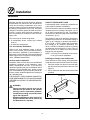
LEG ATTACHMENT
1. Put the oven onto a genie lift with the bottom
of the oven down.
2. Each leg is attached by three bolts to the unĆ
derside of the oven base frame.
CASTER ATTACHMENT
1. Bolt supports to oven with 1/2Ć13 hex head
bolts (casters with brakes should be facing
front of oven.)
2. Carefully place oven onto the casters. (It will
be necessary to have several persons lift oven
off the pallet and set it onto the casters). EnĆ
gage brakes on front casters.
NOTE: A fixed restraint must be provided if castĆ
ers are used in conjunction with a flexible
connector for movable appliances. This
restraint must secure the oven to a nonĆ
movable surface to eliminate stress on the
connector. If the oven is moved, the reĆ
straint must be reconnected after the oven
is returned to it's normal position.

Installation
6
Oven Assembly
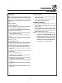
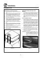
DOUBLE SECTION ASSEMBLY
1. Fasten 12" (305 mm) legs to lower section.
2. Remove the sheet metal flue cover on bottom
of UPPER SECTION FLUE ONLY and save the
two screws.
3. Fasten crown angle leg frame to upper secĆ
tions.
4. Insert double oven flue connector into upper
oven section flue until it is flush with the base
angle. Temporarily hold in place with tape.
5. Install upper section on bottom section.
6. Remove tape and slide flue connector into
position over the collar of the bottom section.
See Figure 2.
7. Fasten flue connector to bottom section with
screws from the flue cover.
8. Install drafthood or draft diverter with screws
provided.
Figure 2
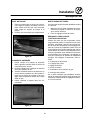
3 PIECE DEFLECTOR ASSEMBLY
1. Deflectors are shipped in place in the oven. No
assembly is required.
2. Remove the shipping clip located in the back
center of each deflector before inserting twoĆ
piece shelf assembly.
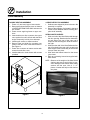
ULTRA ROKITE SHELVES
1. Slide one half of the Ultra Rokite shelf through
the door opening. Rest the shelf on the deflecĆ
tor and slide to the rear of the oven until it
drops into the shelf support. Slide the shelf to
the right.
2. Slide the other half of the Ultra Rokite shelf on
top of first shelf to the rear until it is within the
shelf support. Slide it all the way to the left until
it drops down into place.
3. Slide both shelf halves inward so the center
joint closes.
4. Refer to preĆheating instructions supplied with
Ultra Rokite.
NOTE: Because of the weight of the Ultra Rokite
shelves, take care to avoid injury to yourĆ
self or damage to the shelves when sliding
sections into the oven. Use of 1" x 4"
pieces of lumber will help to slide shelves
into place.
Figure 3

Installation
7
Oven Assembly
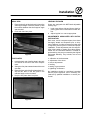
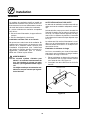
DECK SEAL
1. Place the long lip of the deck seal in front of the
shelf support angle. Place the shorter lip with
the notches between the shelf support angle
and the shelf.
2. Push seal down into place.
Figure 4
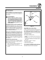
FLUE PLATES
1. Insert the back end of the flue plate in the vertiĆ
cal channel in the rear of the oven compartĆ
ment.
2. Swing the flue plate outward toward the oven
side wall.
3. Raise the front end of the flue plate about 1/2".
slip the two tabs on the flue plate in the
matched angle on the front wall.
4. Drop the flue plate down into place.
Figure 5
LEVELING THE OVEN
Ovens are equipped with NSF listed adjustable
sanitary legs.
1. Level ovens side to side and front to back by
placing spirit level on base frame of lower secĆ
tion.
2. Adjust leg feet in or out as appropriate.
ADJUSTMENTS ASSOCIATED WITH INITIAL
INSTALLATION
Each oven, and its component parts, have been
thoroughly tested and inspected prior to shipĆ
ment. However, it is often necessary to further test
or adjust the oven as part of a normal and proper
installation. These adjustments are the responsiĆ
bility of the installer, or dealer. Since these adjustĆ
ments are not considered defects in material or
workmanship, they are not covered by the Original
Equipment Warranty. They include, but are not
limited to:
D calibration of the thermostat
D adjustment of the doors
D burner adjustments
D leveling
D testing of gas pressure
D tightening of fasteners
No installation should be considered complete
without proper inspection, and if necessary, adĆ
justment by qualified installation or service perĆ
sonnel.

Installation
8
Ventilation
Blodgett gas deck ovens are direct fired. Heat and
flue products from the burners are introduced diĆ
rectly into the baking compartment. As a result,
improper venting can have a detrimental effect on
the baking characteristics of the oven. A properly
designed ventilation system will allow the oven to
function properly, while removing unwanted vaĆ
pors and products of combustion from the operĆ
ating area.
This oven may be vented using either:
D A mechanically driven, canopy type, exhaust
hood, or
D A direct flue arrangement.
U.S. and Canadian installations
Refer to your local ventilation codes. In the abĆ
sence of local codes, refer to the National ventilaĆ
tion code titled, Standard for the Installation of
Equipment for the Removal of Smoke and Grease
Laden Vapors from Commercial Cooking EquipĆ
ment", NFPAĆ96ĆLatest Edition.
General export installations
Installation must conform with Local and National
installation standards. Local installation codes
and/or requirements may vary. If you have any
questions regarding the proper installation and/or
operation of your Blodgett oven, please contact
your local distributor. If you do not have a local disĆ
tributor, please call the Blodgett Oven Company at
0011Ć802Ć860Ć3700.
THE BLODGETT OVEN COMPANY CANNOT ASĆ
SUME RESPONSIBILITY FOR LOSS OR DAMAGE
SUFFERED AS A RESULT OF IMPROPER INSTALĆ
LATION.
WARNING:
Failure to properly vent the oven can be
hazardous to the health of the operator
and may result in operational problems,
unsatisfactory baking and possible damĆ
age to the equipment.
Damage sustained as a direct result of imĆ
proper ventilation will not be covered by
the Manufacturer's warranty.
CANOPY TYPE EXHAUST HOOD
A mechanically driven, canopy type exhaust hood
is the preferred method of ventilation.
The hood should be sized to completely cover the
equipment plus an overhang of at least 6" (15 cm)
on all sides not adjacent to a wall. The distance
from the floor to the lower edge of the hood should
not exceed 7' (2.1m).
The capacity of the hood should be sized approĆ
priately with provisions for an adequate supply of
make up air. Capacity is generally expressed in
ft
3
/min (CFM). 1 CFM of natural gas burned with
just enough air for complete combustion proĆ
duces 11 CFM of combustion products. In virtually
all appliances some excess air is used. This volĆ
ume of excess air is added to the flue products
flowing from the appliance.
NOTE: Consult your local exhaust hood contracĆ
tor for your specific installation.
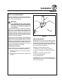
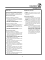
Installing the canopy hood draft diverter
Ovens ordered for hood venting are supplied with
a draft diverter. Install the draft diverter as follows:
1. Place the diverter over the flue connector with
the open area facing the front of the oven. See
Figure 6.
2. Secure both ends with the sheet metal screws
provided.
Front of
Oven
Draft Diverter
Figure 6

Installation
9
Ventilation
DIRECT FLUE ARRANGEMENT
When the installation of a mechanically driven exĆ
haust hood is impractical the oven may be vented
by a direct flue arrangement.
WARNING!!
It is essential that the direct flue be
installed as follows. Incorrect installation
will result in unsatisfactory baking and
oven damage.
The flue must be class B or better with a diameter
of 10" (25.4 cm). The height of the flue should rise
6Ć8 ft (2Ć2.5 m) above the roof of the building or any
proximate structure. Never direct vent the oven
into a hood. The flue should be capped with a UL
Listed type vent cap to isolate the unit from exterĆ
nal environmental conditions.
The direct vent cannot replace air consumed and
vented by the oven. Provisions must be made to
supply the room with sufficient makeĆup air. Total
makeĆup air requirements for each oven section
should be approximately 30 CFM per section. To
increase the supply air entering the room, a venĆ
tilation expert should be consulted.
Installing the draft hood
Ovens ordered for direct venting are supplied with
a draft hood. Install the draft hood as follows:
1. Place the draft hood over the flue connector.
See Figure 7.
2. Secure both ends with the sheet metal screws
provided.
Front of
Oven
Draft Hood
Flue
Figure 7
VENTING PROBLEMS
Blodgett gas deck ovens use the natural principal
of heat rising as the basic method of ventilation. If
the venting of any deck oven is either restricted or
forced in any way the baking characteristics of the
oven will be adversely affected.
Examples of forced venting include:
D installation of a fan in a direct vent pipe
D use of a canopy type hood without the draft diĆ
verter
Examples of restricted venting include:
D use of tees and elbows
D long horizontal runs
Insufficient makeĆup air can cause heated air and
combustibles to remain in the oven shortening the
life of the components.

Installation
10
Utility Connections - Standards and Codes
THE INSTALLATION INSTRUCTIONS CONĆ
TAINED HEREIN ARE FOR THE USE OF QUALIĆ
FIED INSTALLATION AND SERVICE PERSONNEL
ONLY. INSTALLATION OR SERVICE BY OTHER
THAN QUALIFIED PERSONNEL MAY RESULT IN
DAMAGE TO THE OVEN AND/OR INJURY TO
THE OPERATOR.
Qualified installation personnel are individuals, a
firm, a corporation, or a company which either in
person or through a representative are engaged
in, and responsible for:
D the installation or replacement of gas piping
and the connection, installation, repair or servĆ
icing of equipment.
Qualified installation personnel must be experiĆ
enced in such work, familiar with all precautions
required, and have complied with all requirements
of state or local authorities having jurisdiction.
U.S. and Canadian installations
Installation must conform with local codes, or in
the absence of local codes, with the National Fuel
Gas Code, NFPA54/ANSI Z223.1-Latest Edition,
the Natural Gas Installation Code CAN/CGAĆ
B149.1 or the Propane Installation Code, CAN/
CGAĆB149.2 as applicable.
General export installations
Installation must conform with Local and National
installation standards. Local installation codes
and/or requirements may vary. If you have any
questions regarding the proper installation and/or
operation of your Blodgett oven, please contact
your local distributor. If you do not have a local disĆ
tributor, please call the Blodgett Oven Company at
0011Ć802Ć860Ć3700.

Installation
11
Gas Connection
GAS PIPING
A properly sized gas supply system is essential for
maximum oven performance. Piping should be
sized to provide a supply of gas sufficient to meet
the maximum demand of all appliances on the line
without loss of pressure at the equipment.
Example:
NOTE: BTU values in the following example are
for natural gas.
You purchase a 1048ĆBL deck oven to add to your
existing cook line.
1. Add the BTU rating of your current appliances.
Pitco Fryer 120,000 BTU
6 Burner Range 60,000 BTU
Convection Oven 50,000 BTU
Total 230,000 BTU
2. Add the BTU rating of the new oven to the toĆ
tal.
Previous Total 230,000 BTU
1048ĆB 85,000 BTU
New Total 315,000 BTU
3. Measure the distance from the gas meter to
the cook line. This is the pipe length. Let's say
the pipe length is 40' (12.2 m) and the pipe
size is 1" (2.54 cm).
4. Use the appropriate table to determine the toĆ
tal capacity of your current gas piping.
The total capacity for this example is 320,000
BTU. Since the total required gas pressure,
315,000 BTU is less than 320,000 BTU, the
current gas piping will not have to be inĆ
creased.
NOTE: The BTU capacities given in the tables are
for straight pipe lengths only. Any elbows
or other fittings will decrease pipe capaciĆ
ties. Contact your local gas supplier if you
have any questions.
Maximum Capacity of Iron Pipe in Cubic Feet
of Natural Gas Per Hour
(Pressure drop of 0.5 Inch W.C.)
Pipe
Length
Nominal Size, Inches
L
eng
th
(ft)
3/4" 1" 1Ć1/4" 1Ć1/2" 2"
10 360 680 1400 2100 3950
20 250 465 950 1460 2750
30 200 375 770 1180 2200
40 170 320 660 990 1900
50 151 285 580 900 1680
60 138 260 530 810 1520
70 125 240 490 750 1400
80 118 220 460 690 1300
90 110 205 430 650 1220
100 103 195 400 620 1150
From the National Fuel Gas Code Part 10 Table 10Ć2
Maximum Capacity of Pipe in Thousands of
BTU/hr of Undiluted P.P. Gas at 11" W.C.
(Pressure drop of 0.5 Inch W.C.)
Pipe Length
(ft)
Outside Diameter, Inches
pg
(ft)
3/4" 1" 1Ć1/2"
10 608 1146 3525
20 418 788 2423
30 336 632 1946
40 287 541 1665
50 255 480 1476
60 231 435 1337
70 215 404 1241
80 198 372 1144
90 187 351 1079
100 175 330 1014
From the National Fuel Gas Code Part 10 Table 10Ć15

Installation
12
Gas Connection
PRESSURE REGULATION AND TESTING
Each section of the 1048ĆB series oven is rated at
120,000 BTU per hour (35.2 kW) or 85,000 BTU
per hour (24.9 kW). At full demand, each 120,000
BTU section 1048ĆB requires 120 cubic feet per
hour (3.2 m
3
) Natural gas or 47 cubic feet per hour
(1.3 m
3
) Propane gas. Each 85,000 BTU section
1048ĆBL oven requires 85 cubic feet per hour (2.4
m
3
) Natural gas or 33 cubic feet per hour (0.9 m
3
)
Propane gas. Each oven has been adjusted at the
factory to operate with the type of gas specified on
the rating plate.
Inlet Pressure
Natural Propane
Min Max Min Max
W.C. 7.0 10.5 11.0 13.0
kPa 1.43 2.61 2.74 3.23
Manifold Pressure
Natural Propane
W.C. 3.5 10.0
kPa .87 2.49
D Inlet Pressure - the pressure of the gas before
it reaches the oven.
D Manifold Pressure - the pressure of the gas
as it enters the main burner(s).
D Min - the minimum pressure recommended to
operate the oven.
D Max - the maximum pressure at which the
manufacturer warrants the oven's operation.
Each oven is supplied with a regulator to maintain
the proper gas pressure. The regulator is essenĆ
tial to the proper operation of the oven and
must be installed. It is preset to provide the oven
with 3.5" W.C. (0.87 kPa) for natural gas and 10.5"
W.C. (2.50 kPa) for Propane at the manifold.
DO NOT INSTALL AN ADDITIONAL REGULATOR
WHERE THE OVEN CONNECTS TO THE GAS
SUPPLY UNLESS THE SUPPLY EXCEEDS THE
MAXIMUM PRESSURE.
Due to the decrease in oxygen at higher elevaĆ
tions, above 2000', the unit may need to be reĆ
rated. (The orifice size may need to be adjusted to
accomodate different air pressures at higher
elevations.) If not rerated, incomplete combustion
may occur releasing Aldehydes and CO or Carbon
Monoxide. Any of these are unacceptable and
may be hazardous to the health of the operator.
Prior to connecting the oven, gas lines should be
thoroughly purged of all metal filings, shavings,
pipe dope, and other debris. After connection, the
oven should be checked for correct gas pressure.
Installation must conform with local codes, or in
the absence of local codes, with the National Fuel
Gas Code, NFPA54/ANSI Z223.1-Latest Edition,
the Natural Gas Installation Code CAN/CGAĆ
B149.1 or the Propane Installation Code, CAN/
CGAĆB149.2 as applicable.
The oven and its individual shutoff valve must be
disconnected from the gas supply piping system
during any pressure testing of that system at test
pressures in excess of 1/2 psig (3.45kPa).
The oven must be isolated from the gas supply
piping system by closing its individual manual
shutoff valve during any pressure testing of the
gas piping system at test pressures equal or less
than 1/2 psig (3.45kPa).

Installation
13
Gas Connection
GAS HOSE RESTRAINT
If the oven is mounted on casters, a commercial
flexible connector with a minimum of 3/4" (1.9 cm)
inside diameter must be used along with a quick
connect device.
The restraint, supplied with the oven, must be
used to limit the movement of the unit so that no
strain is placed upon the flexible connector. With
the restraint fully stretched the connector should
be easy to install and quick connect.
The restraint (ie: heavy gauge cable) should be
1,000 lb. (453 kg) test load and should be attached
without damaging the building. DO NOT use the
gas piping or electrical conduit for the attachment
of the permanent end of the restraint! Use anchor
bolts in concrete or cement block. On wooden
walls, drive hi test wood lag screws into the studs
of the wall.
1. Mount the supplied bracket to the leg bolt just
below the gas inlet. See Figure 8.
2. The clip on restraining cable can be attached
to the mounting bracket.
Restraint
Cable Bracket
Back of Oven
Double stacked unit shown. Use the same procedure for
single units with 25" (64 cm) legs.
Figure 8
WARNING!!
If the restraint is disconnected for any
reason it must be reconnected when the
oven is returned to its original position.
U.S. and Canadian installations
The connector must comply with the Standard for
Connectors for Movable Gas Appliances, ANSI
Z21.69 or Connectors For Moveable Gas ApĆ
pliances CAN/CGAĆ6.16 and a quick disconnect
device that complies with the Standard for QuickĆ
Disconnect Devices for Use With Gas Fuel, ANSI
Z21.41 or Quick Disconnect For Use With Gas Fuel
CAN 1Ć6.9. Adequate means must be provided to
limit the movement of the appliance without deĆ
pending on the connection and the quick disconĆ
nect device or its associated piping. Adequate
means must be provided to limit the movement of
the appliance without depending on the connecĆ
tion and the quick disconnect device or its associĆ
ated piping.
General export installations
The restraint and quick connect must conform
with Local and National installation standards. LoĆ
cal installation codes and/or requirements may
vary. If you have any questions regarding the propĆ
er installation and/or operation of your Blodgett
oven, please contact your local distributor. If you
do not have a local distributor, please call the
Blodgett Oven Company at 0011Ć802Ć860Ć3700.

Operation
14
Safety Information
THE INFORMATION CONTAINED IN THIS SECĆ
TION IS PROVIDED FOR THE USE OF QUALIFIED
OPERATING PERSONNEL. QUALIFIED OPERATĆ
ING PERSONNEL ARE THOSE WHO HAVE
CAREFULLY READ THE INFORMATION CONĆ
TAINED IN THIS MANUAL, ARE FAMILIAR WITH
THE FUNCTIONS OF THE OVEN AND/OR HAVE
HAD PREVIOUS EXPERIENCE WITH THE OPĆ
ERATION OF THE EQUIPMENT DESCRIBED. ADĆ
HERENCE TO THE PROCEDURES RECOMĆ
MENDED HEREIN WILL ASSURE THE
ACHIEVEMENT OF OPTIMUM PERFORMANCE
AND LONG, TROUBLEĆFREE SERVICE.
SAFETY TIPS
For your safety read before operating
What to do if you smell gas:
D DO NOT try to light any appliance.
D DO NOT touch any electrical switches.
D Use an exterior phone to call your gas supplier
immediately.
D If you cannot reach your gas supplier, call the
fire department.
What to do in the event of a power failure:
D Turn all switches to off.
NOTE: In the event of a shutĆdown of any kind, alĆ
low a five (5) minute shut off period before
attempting to restart the oven.
General safety tips:
D DO NOT use tools to turn off the gas control. If
the gas cannot be turned off manually do not try
to repair it. Call a qualified service technician.
D If the oven needs to be moved for any reason,
the gas must be turned off and disconnected
from the unit before removing the restraint
cable. Reconnect the restraint after the oven
has been returned to its original location.
D DO NOT remove the control cover unless the
oven is unplugged.
Please take the time to read the following operatĆ
ing instructions. They are the key to the successful
operation of your Blodgett deck oven.

Operation
15
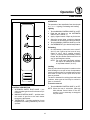
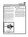
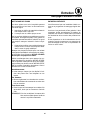
Oven Control
1
2
3
CONTROL DESCRIPTION
1. AUTOMATIC SAFETY PILOT VALVE - proĆ
vides complete gas shutĆoff in the event of piĆ
lot failure.
2. MANUAL CONTROL VALVE - provides manĆ
ual control of gas flow to the main burner
through the thermostat.
3. THERMOSTAT - Provides regulation of oven
temperature at setting selected by the oven
operator.
OPERATION
The operation of the 1048 Series Oven is as simple
as 1, 2, 3. - Lighting, Preheating and Loading.
Lighting
1. Turn the MANUAL CONTROL VALVE (2) to OFF.
2. Push the red button on the AUTOMATIC
SAFETY PILOT VALVE (1).
3. Apply a lighted match or taper to pilot burner.
4. After pilot burner lights, continue to depress
red button for about 30 seconds and release.
5. Turn the MANUAL CONTROL VALVE (2) to ON.
6. Set THERMOSTAT (3) to desired temperature.
Preheating
1. On initial startup, preheat the oven to 600_F
(315_C) over a period of four hours in increĆ
ments of 100_F (55_C) starting at 300_F
(149_C). Check the oven periodically. This will
temper the Ultra Rokite shelves and burn off
any oil and fiberglass residue.
NOTE: The 1048 (with Ultra Rokite shelves)
will require an additional 20 minutes
on a preheat to 600_F (315_C).
Loading
Pizza in pans should be placed in rotation on the
shelf allowing it to recover its loss of temperature
from the previous bake. Do not allow pans to touch
each other or sides of oven. Open doors as selĆ
dom as possible.
The deck is intended for cooking pizza and bread
products, other types of food may be cooked in
pans or containers.
To turn the oven off
1. Turn the MANUAL CONTROL VALVE (1) to OFF.
NOTE: When the oven is shut down, place the
Main Manual Control Valve in the OFF
position. It is not necessary to extinguish
the pilot flame.
La page est en cours de chargement...
La page est en cours de chargement...
La page est en cours de chargement...
La page est en cours de chargement...
La page est en cours de chargement...
La page est en cours de chargement...
La page est en cours de chargement...
La page est en cours de chargement...
La page est en cours de chargement...
La page est en cours de chargement...
La page est en cours de chargement...
La page est en cours de chargement...
La page est en cours de chargement...
La page est en cours de chargement...
La page est en cours de chargement...
La page est en cours de chargement...
La page est en cours de chargement...
La page est en cours de chargement...
La page est en cours de chargement...
La page est en cours de chargement...
La page est en cours de chargement...
La page est en cours de chargement...
-
 1
1
-
 2
2
-
 3
3
-
 4
4
-
 5
5
-
 6
6
-
 7
7
-
 8
8
-
 9
9
-
 10
10
-
 11
11
-
 12
12
-
 13
13
-
 14
14
-
 15
15
-
 16
16
-
 17
17
-
 18
18
-
 19
19
-
 20
20
-
 21
21
-
 22
22
-
 23
23
-
 24
24
-
 25
25
-
 26
26
-
 27
27
-
 28
28
-
 29
29
-
 30
30
-
 31
31
-
 32
32
-
 33
33
-
 34
34
-
 35
35
-
 36
36
-
 37
37
-
 38
38
-
 39
39
-
 40
40
-
 41
41
-
 42
42


dans d''autres langues
- English: Blodgett 1048 User guide
Documents connexes
-
Blodgett 1060 Mode d'emploi
-
-
Blodgett 1060 Series Manuel utilisateur
-
-
-
-
Blodgett XR8-E spécification
-
Blodgett 951 Mode d'emploi
-
-
Blodgett DFG-50 Mode d'emploi