La page est en cours de chargement...

MADIGAN
Español p. 22
Français p. 12
MTVS2353SMG-1 | MTVS2353SOK
REV07-02-13
Save these instructions | Conserver ces instructions | Guarde estas instrucciones
MEDIA CONSOLE
CONSOLE MÉDIA
CONSOLA DE MEDIOS

2
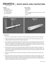
PARTS
A 1 TOP ZZ.2353.A
B 1 SHELF ZZ.2353.B
C 1 BASE ZZ.2353.C
D 1 LEFT TOP SIDE PANEL ZZ.2353.D
E 1 RIGHT TOP SIDE PANEL ZZ.2353.E
F 1 LEFT SIDE PANEL ZZ.2353.F
G 1 RIGHT SIDE PANEL ZZ.2353.G
H 1 LEFT TOP FRONT PANEL ZZ.2353.H
I 1 RIGHT TOP FRONT PANEL ZZ.2353.I
J 1 TOP TRIM ZZ.2353.J
K 1 LEFT FRONT PANEL ZZ.2353.K
L 1 RIGHT FRONT PANEL ZZ.2353.L
M 1 TOP OPENING TRIM ZZ.2353.M
N 1 LEFT OPENING TRIM ZZ.2353.N
O 1 RIGHT OPENING TRIM ZZ.2353.O
P 1 BACK PANEL ZZ.2353.P
HARDWARE
a 37 CAM LOCK
SPARES
INCLUDED
b 37 CAM LOCK DOWEL
c 42 WOOD DOWEL
d 3 LARGE SCREW
e 16 SMALL SCREW
f 2 MOUNTING BRACKET
ANTI-TIP DEVICE
2 SETS
INCLUDED
g 2 LARGE SCREW
h 2 SMALL SCREW
i 1 NYLON STRAP
J 2 ANCHOR
k 1 TOUCH UP PAINT
ASSEMBLY TIPS
Before you begin, locate the instructions and hardware. Take out all the parts and compare them to the
diagrams below. Be sure you have all the parts and can identify them. Two people are required to assemble
this product. Assembly time will take approximately 30-90 minutes.
CARE AND MAINTENANCE
1. Dust your fireplace mantel regularly with a soft non-lint producing cloth or household dusting product.
2. You can clean your fireplace insert with a gentle non-abrasive household cleaner. Make sure to dry
your fireplace immediately with a soft cloth or towel.
A
B
J
D
E
G
H
I
L
K
F
a b
d
e
c
f
g h
i
J
k
M
O
N
P
C

3
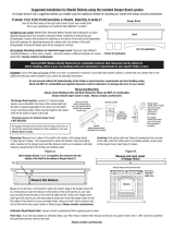
FIREBOX PACKAGE CONTENTS
Q 1 FIREBOX
R 1 REMOTE
S 2 CR2032 BATTERY
T 3 METAL TRIM
U 7 FIREBOX TRIM SCREW
AAA AAA
AAA AAA
ASSEMBLY
Before assembly, use scissors to unwrap the parts from the packaging. DO NOT use a box cutter or
exacto-knife as you may cut into the mantel pieces inside the box and damage the finish. Check for the
hardware bag which is RED and located inside the packaging, taped to the top box. DO NOT discard
any pieces.
1. Locate the base (C). Insert and tighten 6 cam lock dowels (b) into
the base (C). Make sure the threaded side is down so you can inset
and tighten each cam lock dowel (b) into each hole in the base (C).
Locate the top (A) and place it finished side down on a soft clean
surface. Insert and tighten 6 cam lock dowels (b) into the top (A).
Make sure the threaded side is down so you can insert and tighten
each cam lock dowel (b) into each hole in the top (A). Insert 2 wood
dowels (c) into the holes on the underside of the front of the top A.
Line up the holes in the top trim piece J with the wood dowels in the
top A. Push piece J down until flush with the top A. Secure piece J
to top A by inserting 3 long screws (d) into piece J and tightening
until secure.
J
A
Hardware Used
b Cam Lock Dowel x 12
c Wood Dowel x 2
d Large Screw x 3
Hardware Used
c Wood Dowel x 12
Q
S
T
U
2. Locate the left and right top side panels (D & E). Insert 6 wood
dowels (c) into the edges of each panel as shown.
C
D
E
R

4
Hardware Used
b Cam Lock Dowel x 15
4. Locate the top front panel H. Insert 1 cam lock dowel (c) into the
center hole on the back of panel H. Make sure the threaded side is
down so you can insert and tighten each cam lock dowel into the
panels. Insert 2 wood dowels on either end of the top front panel H.
Repeat process for top front panel I.
5. Locate the left and right front panels (K & L). Insert 1 wood dowel
(d) into each the end of each panel K & L. Insert 2 cam lock dowels
into the back of each panel K & L. Insert 2 cam lock dowels into
the outer edge of each panel K & L. Make sure the threaded side is
down so you can insert and tighten each cam lock dowel into each
panel.
3. Insert 6 cam lock dowels (b) into the holes on the top of shelf B.
Make sure the threaded side is down so you can insert and tighten
each cam lock dowel into the panels.
Flip shelf B over and insert 9 cam lock dowels (b) into the holes on
the bottom of shelf B. Make sure the threaded side is down so you
can insert and tighten each cam lock dowel into the panels.
Hardware Used
b Cam Lock Dowel x 2
c Wood Dowel x 4
L
K
H
I
Hardware Used
b Cam Lock Dowel x 8
c Wood Dowel x 4
B
B

5
6. Locate side panels F & G. Insert 6 wood dowels into the edge of
each panel.
7. Line up and insert cam lock dowels and wood dowels on panels
F and K and push together until flush. Insert 2 cam locks into the
holes on panel F. Make sure the arrows on the cam locks are facing
toward panel K. Turn the cam locks to tighten. Do not strip the cam
locks by over tightening.
Repeat process for panels G and L.
F
G
Hardware Used
a Cam Lock x 4
Hardware Used
c Wood Dowel x 12
F
K
G
L
Hardware Used
a Cam Lock x 2
H
D
8. Line up the wood dowels in panel D with the holes in panel H
and the cam lock dowel in panel H with the holes in panel D.
Push together until flush. Insert a cam lock into the center hole at
the bottom of panel D. Make sure the arrows on the cam lock are
facing toward panel H. Turn the cam lock to tighten. Do not strip
the cam lock by over tightening.
Repeat the process for panels E and I.
E
I

6
Hardware Used
a Cam Lock x 6
C
F
G
Hardware Used
a Cam Lock x 6
C
B
9. Line up the wood dowels in the bottom of panels F & K with the
holes in the base C. Also line up the cam lock dowels in the base
C with the holes in the bottom of panels F & K. Push the assembly
of panels F & K down until flush with the base C. Once flush, insert
cam locks at the bottom of panels F & K making sure the arrows on
the cam locks are facing down toward the base C. Turn the cam
locks to tighten. Do not strip the cam locks by over tightening.
Repeat the process for panels G & L.
10. Line up the wood dowels in the top edge of panels F, K, G, & L
with the holes on the bottom of shelf B and the cam lock dowels
in the bottom of shelf B with the holes on the top edge of panels F,
K, G, & L. Push the shelf B down on the mantle assembly until flush.
Insert cam locks into the holes on panels F, K, G, & L. Make sure
the arrows on the cam locks are facing up toward shelf B. Turn the
cam locks to tighten. Do not strip the cam locks by over tightening.
K
L
F
G
K
L

7
Hardware Used
a Cam Lock x 6
B
D
Hardware Used
a Cam Lock x 6
A
11. Line up the wood dowels in panels D & H with the holes on the top
of shelf B and the cam lock dowels on shelf B with the holes in the
bottom edge of panels D & H. Push panels D & H down onto shelf
B until flush. Insert 3 cam locks into the bottom holes of panels D &
H. Make sure the arrows on the cam locks are facing down toward
shelf B. Turn the cam locks to tighten. Do not strip the cam locks by
over tightening.
Repeat process for panels E & I.
12. Note: Top is heavy. It is recommended that 2 people be used at this
point in the assembly.
Line up the wood dowels in the top of the mantel assembly with
the holes in the underside of top A. Also make sure the cam lock
dowels on the underside of top A are lined up with the holes in
the in the top of the mantel assembly. Push top A down until flush.
Insert 6 cam locks into the holes on panels D, H, E, and I. Make
sure the arrows on the cam locks are facing up toward the top A.
Turn the cam locks to tighten. Do not strip the cam locks by over
tightening.
H
I
E
D
H
I
E

8
M
B
N
O
K
L
15. Place panel N, making sure the finished side is facing out, into
the firebox opening and up against panel K. Make sure the wood
dowels in panel N line up with the holes in panel K and the cam
locks dowels in panel K line up with the holes in panel N. Once
panel N is flush with panel K insert 2 cam locks on the back side
of panel N making sure the arrows on the cam locks are facing
toward panel K. Turn the cam locks to tighten. Do not strip the cam
locks by over tightening.
Repeat process for panels O & L.
14. Place panel M, making sure the finished side is facing out, into the
firebox opening and up against panel J on shelf B. Make sure the
wood dowels in panel M line up with the holes in panel J and the
cam lock dowels in panel J line up with the holes in panel M. Once
panel M is flush with panel J insert 3 cam locks on the back side
of panel M making sure the arrows on the cam locks are facing up
toward the shelf B. Turn the cam locks to tighten. Do not strip the
cam locks by over tightening.
13. Locate panels M, N & O. Insert 8 wood dowels into the edge of
each panel.
Hardware Used
a Cam Lock x 3
Hardware Used
a Cam Lock x 4
M
N
O
Hardware Used
c Wood Dowel x 8

9
Hardware Used
U Firebox Trim Screw x 10
16. Locate back panel P. Making sure the finished side is facing in
toward the mantel, line up the holes in panel P with the holes on
the back of the mantel. Secure panel P to the mantel using 16 small
screws (e). Tighten until secure.
P
A
E
Hardware Used
e Small Screw x 16
17. Installing your electric firebox
Refer to the manual included in your electric firebox carton. It will provide
you with the step by step instructions to prepare the electric firebox,
maintenance instructions and the firebox functions prior to installation
in the media console.
The firebox comes with 3 metal brackets and 11 black screws (10
required plus 1 spare). These metal brackets must be attached to all 3
sides of the firebox and 2 sides of the mantel to ensure that your firebox
does not move around as you use it.
Insert your firebox from the rear of the mantel and position between the
two opening trims.
The top trim does not attach to the mantel, just the firebox. If you have any
questions about the firebox please reference the installation instructions
that come with the firebox.
Q
T
U

10
ANTI-TIPPING DEVICE (instructions included with hardware)
1. Attach one of the mounting brackets (f) securely to the back edge
of the furniture. Use the small screws (h).
2. Determine where furniture is to be placed and mark location on
the wall for the other mounting bracket (f) screw holes. You may
need to use 2 anchors (j) if you are attaching to drywall or plaster.
3. Position the bracket over the holes and use the large screws (g) to
securely attach the bracket to wall.
4. Place the furniture so the mounting bracket (f) on the back edge is
in line with the mounting bracket (f) on the wall.
5. Place an end of the nylon restraint strap (i) down through each
bracket (f). Bring both ends together and slide the end of the
nylon strap (i) through the slot in the other end until snug. Pull
down on the end until it snap locks into the slot.
6. Check to make sure the strap (i) is securely laced and locked to
the mounting brackets (f).
Young children may be injured by tipping furniture. The use of a
tipping restraint is highly recommended. This hardware, when
properly installed, could provide protection against the unexpected
tipping of furniture due to improper use.
WARNING: This product is only a deterrent. It is not a substitute for
proper adult supervision.
FIT UP TO 47" PLASMA/LCD/LED TELEVISIONS
MAXIMUM LOAD 55 lb. (25 kg)
MAXIMUM LOAD
30 lb. (13.6kg)
CAUTION: This unit is intended for use only with the products
and maximum weights indicated. Use with other products or
products heavier than the maximum weights indicated may
result in instability causing possible injury.
Note: Flat Panel TVs with base support should be placed
squarely in the center of the stand with no overhang on any side.
Hardware Used
j
Anchor x 2
f
Mounting Bracket x 2
g
Large Screw x 2
h Small Screw x 2
Hardware Used
i Nylon Strap x 1
WALL
WALL
MANTEL

11
WARRANTY
Greenway Home Products is pleased to offer in-home warranty repairs. Please refer to your Firebox Use and Care Guide for warranty
information on your Firebox. Retain receipt as proof of purchase should repair, parts or service be required.
DO NOT RETURN THIS PRODUCT TO THE STORE: Please contact Customer Service at: 1-866-253-0447 Monday to Thursday
from 8:30AM to 5:00PM (EST), Friday from 8:30AM to 4:00PM (EST)
Web: www.greenwayhp.com
Canada: 400 Southgate Dr., Guelph, Ontario, Canada, N1G 4P5
USA: 1270 Flagship Dr., Perrysburg, Ohio, USA, 43551
Limited Warranty Definitions:
Greenway Home Products: (Greenway)Manufacturer.
Mantel: Mantel manufactured by Greenway Home Products.
Purchaser: Purchaser of the Mantel
Distributor: Facility authorized to sell Greenway Home Products.
Warranty Card: Greenway Home Products Limited Warranty Registration Card identifying the Purchaser and product model.
Greenway Limited Warranty:
Greenway warrants to the Purchaser that the Mantel is free from defects in material and workmanship, under normal use and service, for 1
year (1 year limited parts) from the date of purchase.
All warranty repairs must be preauthorized by Greenway Home Products. Greenway will, at its’ option, replace or repair free of charge any
defective part, which the Purchaser shall notify their Distributor or Greenway Home Products within the warranty period. The obligation of
Greenway Home Products under this warranty, is expressly limited to such replacement or repairs.
The provisions of this limited warranty shall not apply to the following:
1. Accidents.
2. Unauthorized repairs or alterations.
3. Normal maintenance.
4. Changes made to other units manufactured after this mantel was manufactured.
5. Incidental damages caused by failure of the mantel such as inconvenience or loss of use.
6. Improper installation.
The provisions of this limited warranty shall not apply to deterioration due to wear and exposure beyond the following limitations:
1. For 180 days from the date of purchase for exterior finished surfaces.
Due to the properties of natural wood, Greenway Home Products makes no warranty against mineraling of wood components.
Greenway Limited Warranty is void unless the following conditions are adhered to:
1. Warranty registration must be completed and returned to a Greenway Home Products.
2. All warranty repairs must be preauthorized by a Greenway repair facility.
3. Greenway reserves the right to inspect defective parts that have been replaced under warranty. Dealer is expected to hold
defective parts for 60 days.
4. Only parts and accessories and other material, available through Greenway Home Products are to be used in the performance
of warranty service.
5. Purchasers are responsible for presenting/notifying their Distributor as soon a problem exists. The warranty repairs should be
completed in a reasonable amount of time from the date of authorization. Not to exceed 30 days past notification.
This limited warranty is expressly in lieu of any other expressed or implied warranty, including any implied warranty or merchantability or
fitness for a particular purpose and of any obligations or liabilities on Greenway Home Products which neither assumes nor
authorizes any other person to assume for it any other liability in connection with the Mantel manufactured by it.
The warranty is null and void if used in commercial or industrial applications.

12
PIÈCES
A 1 DESSUS ZZ.2353.A
B 1 ÉTAGÈRES ZZ.2353.B
C 1 BASE ZZ.2353.C
D 1 PANNEAU LATÉRAL SUPÉRIEUR GAUCHE ZZ.2353.D
E 1 PANNEAU LATÉRAL SUPÉRIEUR DROIT ZZ.2353.E
F 1 PANNEAU GAUCHE EXTÉRIEUR ZZ.2353.F
G 1 PANNEAU DROIT EXTÉRIEUR ZZ.2353.G
H 1 PANNEAU AVANT SUPÉRIEUR GAUCHE ZZ.2353.H
I 1 PANNEAU AVANT SUPÉRIEUR DROIT ZZ.2353.I
J 1 PANNEAU AVANT SUPÉRIEUR ZZ.2353.J
K 1 PANNEAU AVANT GAUCHE ZZ.2353.K
L 1 PANNEAU AVANT DROIT ZZ.2353.L
M 1 PANNEAU SUPÉRIEUR D’OUVERTURE ZZ.2353.M
N 1 PANNEAU D’OUVERTURE GAUCHE ZZ.2353.N
O 1 PANNEAU D’OUVERTURE DROIT ZZ.2353.O
P 1 PANNEAU ARRIÈRE ZZ.2353.P
MATÉRIEL
a 37 VERROUS DE CAME
PIÈCES DE
RECHANGE
INCLUSES
b 37 CHEVILLES DE VERROUILLAGE
c 42 CHEVILLES DE MONTAGE
d 3 GRANDE VIS
e 16 PETITE VIS
f 2 SUPPORT DE MONTAGE
DISPOSITIF ANTI-TIP
2 SETS
INCLUS
g 2 GRANDE VIS
h 2 PETITE VIS
i 1 SANGLE EN NYLON
j
2 ANCRE
k 1 PEINTURE
CONSEILS SUR L’ASSEMBLAGE
Avant de commencer, ayez sous la main les directives d’installation et les articles de quincaillerie. Sortez
toutes les pièces et comparez-les par rapport aux schémas ci-dessous. Assurez vous d’avoir toutes les pièces
et de pouvoir les identifier. L’Assemblage de ce produit nécessite deux personnes. Il vous faudra environ 30-
90 minutes pour faire l’assemblage.
ENTRETIEN ET MAINTENANCE
1. Nettoyez votre manteau de cheminée régulièrement avec un chiffon doux non pelucheux ou avec un
produit ménager pour époussetage.
2. Vous pouvez nettoyer votre foyer avec un nettoyant ménager non abrasif. Assurez-vous de sécher
immédiatement votre foyer avec un chiffon doux ou une serviette.
A
B
J
D
E
G
H
I
L
K
F
a b
d
e
c
f
g h
i
J
k
M
O
N
P
C

13
CONTENU DE LA BOÎTE DE FOYER
Q 1 BOÎTE À COMBUSTION
R 1 TÉLÉCOMMANDE
S 2 PILE CR2032
T 3 SUPPORTS EN MÉTAL
U 7 VIS NOIRES
AAA AAA
AAA AAA
ASSEMBLAGE
Avant de commencer l’assemblage, utilisez des ciseaux pour déballer les pièces de leur emballage.
N’UTILISEZ PAS un couteau pour les boîtes ou un exacto pour ne pas couper le manteau à l’intérieur de la
boîte et pour ne pas endommager la finition. Vérifiez le sac rouge contenant les articles de quincaillerie;
ce sac se trouve à l’intérieur de l’emballage; le sac est fixé à l’aide de ruban adhésif sur la boîte
supérieure. Assurez-vous que vous ne jetez aucune pièce.
1. Repérez la base (C). Insérez et vissez 6 goujons pour verrous à
came (b) dans la base (C). Assurez-vous que le côté fileté fait face
au sol pour pouvoir insérer et serrer chaque goujon (b) dans chacun
des trous de la base (C).
Repérez le haut (A) et placez le côté fini vers le bas sur une surface
lisse et propre. Insérez et vissez 6 goujons pour verrou à came (b)
dans la partie supérieure (A). Assurez-vous que le côté fileté fait
face au sol pour pouvoir insérer et serrer chaque goujon (b) dans
chacun des trous du dessus (A). Insérez 2 goujons de bois (c) dans
les trous en dessous de l’avant du dessus A. Alignez les trous de
la moulure supérieure (pièce J) avec les goujons de bois du dessus
A. Poussez sur la pièce J jusqu’à ce qu’elle soit alignée avec le
dessus A. Attachez la pièce J au dessus A en insérant 3 longues vis
(d) dans la pièce J et serrer à fond.
J
A
Matériel Utilisé
b Chevilles de verrouillage x 12
c Chevilles de montage x 2
d Grande vis x 3
Matériel Utilisé
c Chevilles de montage x 12
Q
S
T
U
2. Repérez les panneaux supérieurs de gauche et de droite (D & E).
Insérez 6 goujons pour verrou à came (c) dans les bords de chaque
panneau comme indiqué.
C
D
E
R

14
4. Repérez le panneau avant supérieur H. Insérez 1 goujon pour
verrou à came (c) dans le trou central à l’arrière du panneau H.
Assurez-vous que le côté fileté fait face au sol pour pouvoir insérer
et serrer chaque goujon dans les panneaux. Insérez 2 goujons de
bois à chaque extrémité du panneau avant supérieure H.
Répétez la procédure pour le panneau avant supérieur I.
5. Repérez les panneaux avant gauche et droite (K & L). Insérez 1
goujon de bois (d) dans chaque extrémité des panneaux K & L.
Insérez 2 goujons pour verrou à came à l’arrière de chacun des
panneaux K & L. Insérez 2 goujons pour verrou à came dans les
extrémités extérieures de chacun des panneaux K & L. Assurez-
vous que le côté fileté fait face au sol pour pouvoir insérez et serrer
chaque goujon dans les panneaux.
3. Insérez 6 goujons pour verrou à came (b) dans les trous sur le dessus
de la tablette B. Assurez-vous que le côté fileté fait face au sol pour
pouvoir insérez et serrer chaque goujon dans les panneaux.
Retournez la tablette B et insérez 9 goujons pour verrou à came (b)
dans les trous au-dessous de la tablette B. Assurez-vous que le côté
fileté fait face au sol pour pouvoir insérez et serrer chaque goujon
dans les panneaux.
B
L
K
B
H
I
Matériel Utilisé
b Chevilles de verrouillage x 15
Matériel Utilisé
b Chevilles de verrouillage x 2
c Chevilles de montage x 4
Matériel Utilisé
b Chevilles de verrouillage x 8
c Chevilles de montage x 4

15
6. Repérez les panneaux latéraux F & G. Insérez 6 goujons pour
verrou à came sur les extrémités de chacun des panneaux.
7. Alignez et insérez les goujons pour verrou à came et les goujons
de bois sur les panneaux F et K et serrez-les jusqu’à ce qu’ils soient
alignés. Insérez 2 goujons pour verrou à came sur le panneau F.
Assurez-vous que les flèches sur les verrous à came pointent vers le
panneau K. Tournez les verrous à came pour le serrer. N’arrachez
pas les verrous à came en les serrant trop.
Répétez l’opération pour les panneaux G et L.
F
G
Matériel Utilisé
a Verrous de came x 4
F
K
G
L
Matériel Utilisé
c Chevilles de montage x 12
Matériel Utilisé
a Verrous de came x 2
H
D
8. Alignez les goujons de bois dans le panneau D avec les trous du
panneau H et alignez les goujons pour verrou à came du panneau
H avec les trous dans le panneau D. Serrez-les jusqu’à ce qu’ils
soient alignés.
Insérez un verrou à came dans le trou central dans le bas du
panneau D. Assurez-vous que les flèches sur le verrou à came
pointent vers le panneau H. Tournez le verrou à came pour le
serrer. N’arrachez pas les verrous à came en les serrant trop.
Répétez le processus pour les panneaux E et I.
E
I

16
C
F
G
Matériel Utilisé
a Verrous de came x 6
C
B
9. Alignez les goujons de bois dans le bas des panneaux F & K avec
les trous dans la base C. Alignez aussi les goujons pour verrou à
came dans la base C avec les trous au bas des panneaux F & K.
Appuyez sur l’assemblage des panneaux F & K jusqu’à ce qu’elle
soit alignée à la base C. Une fois alignés, insérez des verrous
à came au bas des panneaux F & K en vous s’assurant que les
flèches sur les verrous à came sont orientées vers le bas vers la
base C. Tournez le verrou à came pour le serrer. N’arrachez pas
les verrous à came en les serrant trop.
Répétez le processus pour les panneaux G & L.
10. Alignez les goujons de bois dans l’extrémité supérieure des
panneaux F, K, G, & L avec les trous en dessous de la tablette B et
alignez les goujons pour verrou à came au-dessous de la tablette
B avec les trous dans l’extrémité supérieure de panneaux F, K, G,
& L. Appuyez sur la tablette B jusqu’à ce qu’elle soit alignée à
l’assemblage du manteau. Insérez les verrous à came dans les trous
sur les panneaux F, K, G, & L. Assurez-vous que les flèches sur les
verrous à came soient orientées vers le haut, vers la tablette B.
Tournez le verrou à came pour le serrer. N’arrachez pas les verrous
en les serrant trop.
Matériel Utilisé
a Verrous de came x 6
K
L
F
G
K
L

17
B
D
Matériel Utilisé
a Verrous de came x 6
A
11. Alignez les goujons de bois dans les panneaux D & H avec les
trous sur le dessus de la tablette B et alignez les goujons pour
verrou à came sur la tablette B avec les trous dans l’extrémité
inférieure des panneaux D & H. Appuyez sur les panneaux D &
H jusqu’à ce qu’ils soient alignés avec la tablette B. Insérez 3
verrous à came dans les trous inférieurs des panneaux D & H.
Assurez-vous que les flèches sur les verrous à came sont orientées
vers le bas, vers la tablette B. Tournez le verrou à came pour le
serrer. N’arrachez pas les verrous à came en les serrant trop.
Répétez l’opération pour les panneaux E & I.
12. Remarque : le dessus est lourd. À cette étape, nous recommandons
que l’assemblage soit fait par deux personnes.
Alignez les goujons de bois dans la partie supérieure de
l’assemblage du manteau de la cheminée avec les trous dans la
partie inférieure du dessus A. Assurez-vous également que les
goujons pour verrou à came sur la partie inférieure du dessus A
sont alignés avec les trous dans la partie supérieure de l’assemblage
du manteau. Appuyez sur le dessus A jusqu’à ce qu’il soit aligné.
Insérez 6 verrous à came dans les trous sur les panneaux D, H, E
et I. Assurez-vous que les flèches sur les verrous à came sont
orientées vers le dessus A. Tournez le verrou à came pour le serrer.
N’arrachez pas les verrous à came en les serrant trop.
Matériel Utilisé
a Verrous de came x 6
H
I
E
D
H
I
E

18
M
B
N
O
K
L
15. En vous assurant que le côté fini soit tourné vers l’extérieure,
installez le panneau N dans l’ouverture du foyer et contre le
panneau K. Assurez-vous que les goujons de bois dans le panneau
N soient vis-à-vis les trous dans le panneau K et que les goujons
pour verrou à came du panneau K soient vis-à-vis les trous dans
le panneau N. Une fois le panneau N aligné au panneau K,
insérez 2 verrous à came derrière le panneau N en vous assurant
que les flèches sur les verrous à came soient orientées vers le
panneau K. Tournez le verrou à came pour le serrer. N’arrachez
pas les verrous à came en les serrant trop.
Répétez l’opération pour les panneaux O & L.
14. En vous assurant que le côté fini soit tourné vers l’extérieure,
installez le panneau M dans l’ouverture du foyer et contre le
panneau J sur la tablette B. Assurez-vous que les goujons de bois
sur le panneau M soient vis-à-vis les trous dans le panneau J et que
les goujons pour verrou à came dans le panneau J soient vis-à-vis
les trous dans le panneau M. Une fois le panneau M aligné au
panneau J, insérez 3 verrous à came derrière le panneau M en
vous assurant que les flèches sur les verrous à came soient orientées
vers le haut, vers la tablette B. Tournez le verrou à came pour le
serrer. N’arrachez pas les verrous à came en les serrant trop.
13. Repérez les panneaux M, N & O. Insérez 8 goujons pour verrou
à came sur les extrémités de chacun des panneaux.
Matériel Utilisé
a Verrous de came x 3
Matériel Utilisé
a Verrous de came x 4
M
N
O
Matériel Utilisé
c Chevilles de montage x 8

19
Matériel Utilisé
U Vis noires x 10
16. Repérez le panneau arrière P. En vous assurant que le côté fini soit
tourné vers l’intérieure du foyer, alignez les trous dans le panneau
P avec ceux derrière le foyer. Attachez le panneau P au foyer en
utilisant 16 petites vis (e). Serrez à fond.
P
A
E
Matériel Utilisé
e Petit vis x 16
17. Installation du foyer électrique
Consultez le manuel fourni avec la boîte à combustion électrique. Il
vous fournira les instructions étape par étape pour préparer la boîte à
combustion, les instructions pour l’entretien et les fonctions de la boîte à
combustion avant l’installation dans la console média.
Le foyer inclus 3 supports en métal et 11 vis noires (10 requises plus
1 en surplus). Ces supports en métal doivent être fixés aux 3 côtés du
foyer et aux 2 côtés du manteau de cheminée pour s’assurer que votre
foyer ne se déplace pas lorsque vous l’utiliser.
Insérez votre foyer électrique par l’arrière du mantel et placez-le entre
les 2 jambes du mantel.
La moulure supérieure n’est pas fixée au manteau de cheminée, seulement
au foyer. Si vous avez des questions au sujet du foyer, veuillez consulter
les directives d’installation incluses avec le foyer.
Q
T
U

20
DISPOSITIF ANTI-BASCULEMENT (instructions incluses avec le matériel)
1. Fixez l’un des supports de montage (f) en toute sécurité sur le
bord arrière du meuble. Utilisez les vis plus courtes (h).
2. Déterminer où le meuble va être situé et marquer l’emplacement
sur le mur pour les supports de fixation (f). Vous pouvez avoir
besoin d’utiliser 2 chevilles (j) si vous attachés au mur ou le plâtre.
3. Positionner le support dans les trous et utiliser les vis plus longues
(g) pour fixer solidement le support (f) au mur.
4. Place le meuble pour que le support (f) à l’arrière soit en ligne
avec le support (f) sur le mur.
5. Placez une retenue en nylon (i) à travers chaque support (f).
Ramenez les deux extrémités ensemble et faites glisser le bout
dans la fente de l’autre extrémité jusqu’à ce qu’ils soient ensemble.
Tirez sur l’extrémité jusqu’à ce qu’il fermoirs dans la fente.
6. Assurez-vous que les retenues (i) sont bien lacées et verrouillé
pour les supports (f).
Les jeunes enfants peuvent être blessés par basculement de meubles.
L’utilisation d’un dispositif de retenue de basculement est fortement
recommandée. Ce matériel, lorsqu’il est correctement installé, pourrait
fournir une protection contre le basculement inattendu de meubles
par une utilisation inadéquate.
AVERTISSEMENT: Ce produit est uniquement un moyen de
dissuasion. Ce n’est pas un substitut de surveillance des adultes.
SUPPORT DES TÉLÉVISEURS PLASMA/LCD DE 47PO
CHARGEMENT MAXIMALE 55 lb. (25 kg)
CHARGEMENT MAXIMALE
30 lb. (13.6kg)
ATTENTION: cette unité est uniquement compatible avec les
produits spécifiés et ne peut supporter que la charge maximale
indiquée. Le fait d’utiliser cette unité avec d’autres produits ou
avec des produits dont le poids excède la charge maximale
indiquée peut entraîner de l’instabilité et causer des blessures.
Note: les téléviseurs à écran plat d’une base de soutien doivent
être placés complètement au centre du support sans qu’aucune
partie de la base dépasse.
Matériel Utilisé
j
Ancre x 2
f Support de montage x 2
g Grand vis x 2
h Petit vis x 2
Matériel Utilisé
i Sangle en Nylon x 1
MUR
MUR
MANTEAU
/