Delta 26-2251 Le manuel du propriétaire
- Catégorie
- Scies à onglet
- Taper
- Le manuel du propriétaire
Ce manuel convient également à

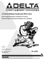
12-inch Sliding Compound Miter Saw
Scie à onglets composée coulissante 12 pouces
26-2251
Instruction Manual
Manual d’utilisation
Manual de instrucciones
Français (26)
Español (51)
To reduce the risk of serious injury, thoroughly read and comply with all warnings and instructions in this manual and on product
KEEP THIS MANUAL NEAR YOUR PRODUCT FOR EASY REFERENCE AND TO INSTRUCT OTHERS
Sierra de inglete compuesta deslizante de 12 pulgadas
www.DeltaMachinery.com

2 3
TABLE OF CONTENTS
IMPORTANT SAFETY INSTRUCTIONS
CAREFULLY READ AND FOLLOW ALL WARNINGS AND INSTRUCTIONS ON YOUR PRODUCT
AND IN THIS MANUAL. SAVE THIS MANUAL. MAKE SURE ALL USERS ARE FAMILIAR WITH ITS
WARNINGS AND INSTRUCTIONS WHEN USING THE TOOL. Improper operation, maintenance or modication of
tools or equipment could result in serious injury and/or property damage.
NOTE: The manual cover illustrates the current production model. All other illustrations contained in the manual are representative
only and may not be exact depictions of the actual labeling or accessories included. They are intended for illustrative purposes only.
Important Safety Instructions .................................. 3
Safety Logos .................................................................. 3
General Power Tool Safety Warnings ...................... 4
Safety Instructions For Miter Saws .......................... 5
Proposition 65 Warning .............................................. 5
Power Connections ..................................................... .6
Double Insulation ......................................................... .6
Electrical Connection ..................................................... 7
Polarized Plugs .............................................................. 7
Extension Cords ............................................................ 7
Features ......................................................................... 7
Product Specications.................................................... 7
Know Your Compound Miter Saw .................................... 9
Unpacking ...................................................................... 9
Removing Contents From Packing .................................. 9
Packaged Contents List ................................................ 10
Mounting And Transportation ................................. 10
Preparations For Transportation.................................... 10
Mounting Saw To Stable Surface .................................. 11
Assembly ...................................................................... 11
Tools Needed .............................................................. 11
Work Clamp ................................................................ 11
Dust Bag .................................................................... 12
Install/Remove/Replace The Blade ............................... 13
Operation ..................................................................... 14
Cutting Warped Material .............................................. 14
Clamping Wide Workpieces .......................................... 15
Supporting Long Workpieces ........................................ 15
Power Switch Lock ...................................................... 15
Non-Sliding Cuts ......................................................... 16
For Miter Cuts ............................................................. 16
For Bevel Cuts ............................................................ 17
For Compound Miter Cuts ............................................ 17
Slide Cuts ................................................................... 18
Tips For Cutting Crown Molding.................................... 18
Auxiliary Fence ........................................................... 19
Increase Cut Capacity .................................................. 20
Adjustments ................................................................ 21
Align The Blade To Table ............................................. 21
Align The Blade To Fence ............................................. 21
Depth Stop ................................................................. 22
Fence Extension .......................................................... 22
Bevel Lock Tension ..................................................... 22
Slide Resistance .......................................................... 23
Miter Lock Adjustment ................................................. 23
Throat Plate................................................................ 23
Maintenance ................................................................ 24
Keep Machine Clean .................................................... 24
General Maintenance ................................................... 24
Brush Replacement ..................................................... 24
Lubrication ................................................................. 24
Trouble Shooting ........................................................ 24
Failure To Start ........................................................... 24
Accessories .................................................................. 25
Parts, Services Or Warranty Assistance ................ 25
Replacement Parts ...................................................... 25
Free warning Label Replacement .................................. 25
Service and Repairs ..................................................... 25
French ........................................................................... 26
Spanish ......................................................................... 51

3
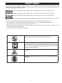
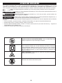
This manual contains information that is important for you to know and understand. This information relates to protecting YOUR
SAFETY and PREVENTING EQUIPMENT PROBLEMS. To help you recognize this information, we use the symbols below. Please read
the manual and pay attention to these sections.
Additional information regarding the safe and proper operation of this tool is available from the following sources:
• Power Tool Institute, 1300 Sumner Avenue, Cleveland, OH 44115-2851 or on-line at www.powertoolinstitute.com
• National Safety Council, 1121 Spring Lake Drive, Itasca, IL 60143-3201
• American National Standards Institute, 25 West 43rd Street, 4 oor, New York, NY 10036 www.ansi.org - ANSI 01.1 Safety
Requirements for Woodworking Machines
• U.S. Department of Labor regulations www.osha.gov
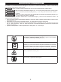
Indicates an imminently hazardous situation which, if not avoided, will result in death or serious injury.
Indicates a potentially hazardous situation which, if not avoided, could result in death or serious injury.
Indicates a potentially hazardous situation which, if not avoided, may result in minor or moderate injury.
Used without the safety alert symbol indicates potentially hazardous situation which, if not avoided, may result in
property damage.
SAFETY LOGOS
Wet Conditions Alert. Do not expose power tools to rain or wet conditions.
Water entering a power tool will increase the risk of electric shock.
Double Insulation.This machine is double insulated. Double insulation is a
concept in safety in electric power tools, which eliminates the need for the usual
three-wire grounded power cord. All exposed metal parts are isolated from the
internal metal motor components with protecting insulation. Double insulated
tools do not need to be grounded.
Pinch Point. Failure to keep your hands out of the pinch points will result in
serious injury.
No Hands. Failure to keep your hands out of the no hand zone will result in
serious injury.

4 5
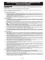
GENERAL POWER TOOL SAFETY WARNINGS
The term “power tool” in the warnings refers to your mains-operated (corded) power tool or BATTERY-operated (cordless) power
tool.
1. Work area safety
a. Keep work area clean and well lit. Cluttered or dark areas invite accidents
b. Do not operate power tools in explosive atmospheres, such as in the presence of ammable liquids,
gases or dust. Power tools create sparks which may ignite the dust or fumes.
c. Keep children and bystanders away while operating a power tool. Distractions can cause you to lose control.
2. Electrical safety
a. Power tool plugs must match the outlet. Never modify the plug in any way. Do not use any adapter with
earthed (grounded) power tools. Unmodied plugs and matching outlets will reduce risk of electric shock
b. Avoid body contact with earthed or grounded surfaces, such as pipes, radiators, ranges and
refrigerators. There is an increased risk of electric shock if your body is earthed or grounded.
c. Do not expose power tools to rain or wet conditions. Water entering a power tool will increase the risk of
electric shock.
d. Do not abuse the cord. Never use the cord for carrying, pulling or unplugging the power tool. Keep cord
away from heat oil, sharp edges or moving parts. Damaged or entangled cords increase the risk of electric
shock.
e. When operating a power tool outdoors, use an extension cord suitable for outdoor use. Use of a cord
suitable for outdoor use reduces the risk of electric shock.
f. If operating a power tool in a damp location is unavoidable, use a ground fault circuit interrupter (GFCI)
protected supply. Use of an GFCI reduces the risk of electric shock.
3. Personal safety
a. Stay alert, watch what you are doing and use common sense when operating a power tool. Do not use
a power tool while you are tired or under the inuence of drugs, alcohol or medication. A moment of
inattention while operating power tools may result in serious personal injury.
b. Use personal protective equipment. Always wear eye protection. Protective equipment such as dust mask,
non-skid safety shoes, hard hat, or hearing protection used for appropriate conditions will reduce personal injuries.
c. Prevent unintentional starting. Ensure the switch is in the o-position before connection to power
source, picking up, or carrying the tool. Carrying power tools with your nger on the switch or energising power
tools that have the switch on invites accidents.
d. Remove any adjusting key or wrench before turning the power tool on. A wrench or a key left attached to a
rotating part of the power tool may result in personal injury.
e. Do not overreach. Keep proper footing and balance at all times. This enables better control of the power tool
in unexpected situations
f. Dress properly. Do not wear loose clothing or jewelery. Keep your hair, clothing and gloves away from
moving parts. Loose clothes, jewelery or long hair can be caught in moving parts.
g. If devices are provided for the connection of dust extraction and collection facilities, ensure these are
connected and properly used. Use of dust collection can reduce dust-related hazards.
h. Do not let familiarity gained from frequent use of tools allow you to become complacent and ignore tool
safety principles. A careless action can cause severe injury within a fraction of a second.
4. Power tool use and care
a. Do not force the power tool. Use the correct power tool for you application. The correct power tool will do
the job better and safer at the rate for which it was designed.
b. Do not use the power tool if the switch does not turn it on and o. Any power tool that cannot be controlled
with the switch is dangerous and must be repaired.
c. Disconnect the plug from the power source before making any adjustments, changing accessories, or
storing power tools. Such preventive safety measures reduce the risk of starting the power tool accidentally.
d. Store idle power tools out of the reach of children and do not allow persons unfamiliar with the power
tool or these instructions to operate the power tool. Power tools are dangerous in the hands of untrained users.
e. Maintain power tools and accessories. Check for misalignment or binding of moving parts , breakage of
parts and any other condition that may aect the power tool’s operation. If damaged, have the power
tool repaired before use. Many accidents are caused by poorly maintained power tools.
Read all safety warnings, instructions, illustrations and specications provided with this power tool.
Failure to follow all instructions listed below may result in electric shock, re and/or serious injury.
Save all warnings and instructions for future reference.

5
SAFETY INSTRUCTIONS FOR MITER SAWS
f. Keep cutting tools sharp and clean. Properly maintained cutting tools with sharp cutting edges are less likely to
bind and are easier to control.
g. Use the power tool, accessories and tools bits etc. in accordance with these instructions, taking into
account the working conditions and the work to be performed. Use of the power tool for operations dierent
from those intended could result in a hazardous situation.
h. Keep handles and grasping surfaces dry, clean and free from oil and grease. Slippery handles and grasping
surfaces do not allow for safe handling and control of the tool in unexpected situations.
5. Service
a. Have your power tool serviced by a qualied repair person using only identical replacement parts. This
will ensure that the safety of the power tool is maintained.
a. Miter saws are intended to cut wood or wood-like products, they cannot be used with abrasive cut-o
wheels for cutting ferrous material such as bars, rods, studs, etc. Abrasive dust causes moving parts such as
the lower guard to jam. Sparks from abrasive cutting will burn the lower guard, the kerf insert and other plastic parts.
b. Use clamps to support the workpiece whenever possible. If supporting the workplace by hand, you must
always keep your hand at least 100mm from either side of the saw blade. Do not use this saw to cut
pieces that are too small to be securely clamped or held by hand. If your hand is placed too close to the saw
blade, there is an increased risk of injury from blade contact.
c. The workpiece must be stationary and clamped or held against both the fence and the table. Do not feed
the workpiece into the blade or cut “freehand” in any way. Unrestrained or moving workpieces could be thrown
at high speeds, causing injury.
d. Push the saw through the workpiece. Do not pull the saw through the workpiece. to make a cut, raise
the saw head and pull it out over the workpiece without cutting, start the motor, press the saw head
down and push the saw through the workpiece. Cutting on the pull stroke is likely to cause the saw blade to
climb on top of the workpiece and violently throw the blade assembly towards the operator.
e. Never cross your hand over the intended line of cutting either in front or behind the saw blade.
Supporting the workpiece “cross handed” i.e. holding the workpiece to the right of the saw blade with your left hand or
vice versa is very dangerous.
f. Do not reach behind the fence with either hand closer than 100mm from either side of the saw blade, to
remove wood scraps, or for any other reason while the blade is spinning. The proximity of the spinning saw
blade to your hand may not be obvious and you may be seriously injured.
g. Inspect your workpiece before cutting. If the workpiece is bowed or warped,clamp it with the outside
bowed face toward the fence. Always make certain that there is no gap between the workpiece, fence
and table along the line of the cut. Bent or warped workpieces can twist or shift and may cause binding on the
spinning saw blade while cutting. There should be no nails or foreign objects in the workpiece.
h. Do not use the saw until the table is clear of all tools, wood scraps, etc., except for the workpiece. Small
debris or loose pieces of wood or other objects that contact the revolving blade can be thrown with high speed.
i. Cut only one workpiece at a time. Stacked multiple workpieces cannot be adequately clamped or braced and may
bind on the blade or shift during cutting.
j. Ensure the miter saw is mounted or placed on a level, rm work surface before use. A level and rm work
surface reduces the risk of the miter saw becoming unstable.
k. Plan your work. Every time you change the bevel or miter angle setting, make sure the adjustable fence
is set correctly to support the workpiece and will not interface with the blade or the guarding system.
Without turning the tool “ON” and with no workpiece on the table, move the saw blade through a complete simulated
cut to assure there will be no interference or danger of cutting the fence.
l. Provide adequate support such as table extensions, saw horses, etc. for a workpiece that is wider or
longer than the table top. Workpieces longer or wider than the miter saw table can if not securely supported. If the cut-o
piece or workpiece tips, it can lift the lower guard or be thrown by the spinning blade.
m. Do not use another person as a substitute for a table extension or as additional support. Unstable support
for the workpiece can cause the blade to bind or the workpiece to shift during the cutting operation pulling you and
the helper into the spinning blade.
n. The cut-o piece must not be jammed or pressed by any means against the spinning saw blade. If
conned, i.e. using length stops, the cut-o piece could get wedged the blade and thrown violently.
o. Always use a clamp or a xture designed to properly support round material such as rods or tubing. Rods
have a tendency to roll while being cut, causing the blade to “bite” and pull the work with your hand into the blade.
p. Let the blade reach full speed before contacting the workpiece. This will reduce the risk of the workpiece
being thrown
q. If the workpiece or blade becomes jammed,turn the miter saw o. Wait for all moving parts to stop
and disconnect the plug from the power source and/or remove the battery pack. Then work to free the
jammed material. Continued sawing with a jammed workpiece could cause loss of control or damage ti the miter
saw.

6 7
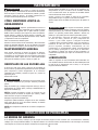
PROPOSITION 65 WARNING:
POWER CONNECTIONS
SAVE THESE INSTRUCTIONS.
Refer to them often and use them to instruct others.
If tool is loaned to someone, also loan them these instructions.
A separate electrical circuit should be used for your machines. This circuit should not be less than #12 wire. Before connecting
the machine to the power line make sure the switch(s) is in the “OFF” position and be sure that the electric current is of the same
characteristics as indicated on the machine. All line connections should make good contact. Running on low voltage will damage the
machine.
This machine is double insulated. Double insulation is a concept in safety in electric power tools, which eliminates the need for
the usual three-wire grounded power cord. All exposed metal parts are isolated from the internal metal motor components with
protecting insulation. Double insulated tools do not need to be grounded.
NOTE: Servicing of a tool with double insulation requires extreme care and knowledge of the system and should be performed by
a qualified service technician. For service, we suggest you return the tool to the nearest authorized service center for repair. Always
use identical replacement parts when servicing.
Your machine is wired for 120 volts, 60 HZ alternating current. Before connecting the machine to the power source, make sure the
switch is in the “OFF” position.
DOUBLE INSULATION
DO NOT EXPOSE THE MACHINE TO RAIN OR OPERATE THE MACHINE IN DAMP LOCATIONS.
r. After nishing the cut, release switch, hold the saw down and wait for the blade to stop before removing
the cut-o piece. Reaching with your hand near the coasting blade is dangerous.
s. Hold the handle, rmly when making an incomplete cut or when releasing the switch before the saw
head is completely in the position. The breaking action of the saw may cause the saw to be suddenly pulled
downward, causing a risk of injury.
t. Saw Head lock pin is for storage and transport only. This saw should never be locked in the down position while
making cuts.
u. Do not operate saw without guards in place.
Some dust created by power sanding, sawing, grinding, drilling, and other construction activities contains
chemicals known to the state of California to cause cancer, birth defects or other reproductive harm. Some examples of these
chemicals are:
• Lead from lead-based paints
• Crystalline silica from bricks and cement and other masonry products
• Arsenic and chromium from chemically-treated lumber
Your risk from these exposures varies, depending on how often you do this type of work. To reduce your exposure to these
chemicals: work in a well-ventilated area and work with approved safety equipment, such as dust masks that are specifically
designed to filter out microscopic particles.
The double insulated system is designed to protect the user from shock resulting from a break in the tool’s
internal insulation. However, it is important to observe normal safety precautions to avoid electrical shock

7
POWER CONNECTIONS
FEATURES
This tool has a precision-built electric motor. It should be connected to a POWER SUPPLY THAT IS 120 VOLTS, 60 HZ, AC ONLY
(NORMAL HOUSEHOLD CURRENT). Do not operate this tool on direct current (DC). A substantial voltage drop will cause a loss of
power and the motor will overheat. If the tool does not operate when plugged into an outlet, double-check the power supply.
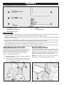
To reduce the risk of electric shock, this equipment has a polarized plug (one blade is wider than the other). This plug will fit in a
polarized outlet only one way. If the plug does not fully fit in the outlet reverse the plug. If it still does not fit, contact a qualified
electrician to install the proper outlet. Do not change the plug in any way.
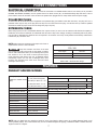
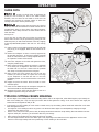
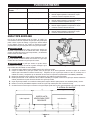
When using a power tool at a considerable distance from a power source, be sure to use an extension cord that has the capacity to
handle the current the tool will draw. An undersized cord will cause a drop in line voltage, resulting in overheating and loss of power.
Use the chart to determine the minimum wire size required in an extension cord. Only round jacketed cords listed by Underwriter’s
Laboratories (UL) should be used.
NOTE: Before using any extension cord, inspect it for loose or
exposed wires and cut or worn insulation.
** Ampere rating (on total data label)
12A- 16A
Cord Length Wire Size
25’ 14 AWG
50’ 12 AWG
** Used on 12 gauge - 20 amp circuit
NOTE: AWG = American Wire Gauge
ELECTRICAL CONNECTION
PRODUCT SPECIFICATIONS
POLARIZED PLUGS
EXTENSION CORDS
Keep the extension cord clear of the work
area. Position the cord so that it will not get caught on lumber,
tools or other obstructions while you are working with a power
tool. Failure to do so can result in serious personal injury.
Check extension cords before each use. If damaged replace
immediately. Never use tool with a damaged cord, since
touching the damaged area could cause electrical shock
resulting in serious injury.
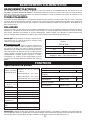
Cutting Capacity
(Maximum nominal lumber
sizes)
0° Miter/0° Bevel: 4” x 14”
(2 x18”) Extended Capacity
45° Miter/ 0° Bevel: 4” x 10”
0° Miter/45° Bevel: 2” x 14”
45° Miter/45° Bevel: 2” x 10”
Baseboard (Vertical) 6.5”
Crown (Vertically Nested) 7.5”
Net Weight 57 lbs
Input 120 V~, 60hz, 15 Amps
Blade Arbor Hole 1”
Blade Diameter 12”
No Load Speed 4,000 r/min (RPM)
Blade Max Speed Rating 5,500 r/min (RPM)
Number of Teeth 60
Blade Thickness 0.07” (1.8 mm)
Blade Kerf 0.1” (2.6mm)
NOTE: Only use blades that are marked for speeds of 4,000 r/min (RPM) or higher. Never use a smaller diameter blade. It will
not be guarded properly. Use crosscut blades only. Do not use blades designed for ripping, combination blades or blades with hook
angles in excess of 7 degrees.
BLADE DESCRIPTIONS
APPLICATION DIAMETER TEETH
Construction Saw Blades (thin kerf with anti-stick rim)
General Purpose 12”(305mm) 40
Fine Crosscuts 12”(305mm) 60
Woodworking Saw Blades (provide smooth, clean cuts)
Fine crosscuts 12”(305mm) 80

9
19
26
25
24
23
22
21
20
18
17
27
28
x2
x2
x2
13
12
1
2
4
3
5
11
10
9
8
7
6
15
16
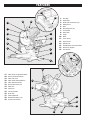
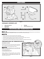
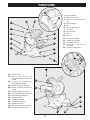
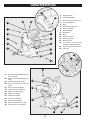
1. Dust Bag
2. Depth Stop
3. Bevel Scale and Pointer (x2)
4. Sliding Fence
5. Base
6. Mounting Holes (x4)
7. Throat Plate
8. Work Table
9. Clamp
10. Blade
11. Lower Guard
12. Upper Guard
13. Spindle Lock
14. On/O Switch and Lockout Hole
15. Back Fence Support
16. Torx Wrench
17. Miter Detent Lock/Unlock Button
18. Bevel Lock/Unlock Handle
19. Miter Lock Knob
20. Miter Detent Override Button
21. Miter Scale and Pointer
22. Bevel Detent Latch (x2)
23. Slide Lock
24. Head Lock
25. Carrying Handle
26. Brush Cap
27. Glide Adjustment
28. Baseboard Position Lock
29. E-Brake (Not Shown)
x4
FEATURESFEATURES
14
Figure 1
Figure 2

9
UNPACKING
KNOW YOUR COMPOUND MITER SAW
1. Dust Collection Bag: The dust bag collects and
contains the saw dust during the cutting operations.
2. Depth Stop: The depth stop plate can be used to
make a non-through cut. The depth stop screw allows
the depth of cut to be adjusted.
3. Bevel Scale and Pointer: These indicate the
current blade bevel position and are adjustable; This
allows for ne calibration of the blade alignment.
4. Adjustable Fence: The fence supports the
workpiece when making all cuts. The extension is
adjustable.
5. Base: Supports the tool and features mounting holes.
6. Mounting Holes (x4): Enables you to securely
mount the tool to a stable surface.
7. Throat Plate (Kerf Plate): The kerf plate supports
the workpiece from underneath, on both sides of the
blade, to minimize workpiece tear out
8. Work Table: The die-cast aluminum work table
provides a level and sturdy work surface.
9. Clamp: The vertical work clamp helps to position and
secure the workpiece to the work table. This provides
for safer operation and more accurate cuts.
10. Blade: A 12 inch blade is included with the compound
miter saw.
11. Lower Guard: The lower blade guard is made of
shock-resistant, see-through plastic that provides
protection from the blade.
12. Upper Guard: Cast aluminum protects user from
blade.
13. Spindle Lock: Engage the spindle lock when
changing the blade in order to hold the blade into
position while you loosen the blade bolt.
14. Power Switch and Power Lockout: This
saw is activated by an easy to use, hand operated,
power switch. When not in use the saw should be
disconnected from the power supply and locked using a
padlock inserted through the lockout hole located on the
power switch.
15. Back Fence Support: These provide workpiece
support and additional cut capacity when the sliding
fence is removed.
16. Torx Wrench: This wrench features two Torx head
sizes and should be used when removing, installing, or
changing the blade.
17. Miter Detent Lock/Unlock Button: This button
allows you to release the miter arm from the positive
stops and freely rotate the miter arm.
18. Bevel Lock/Unlock Handle: This handle locks
the blade bevel angle securely into place. Always lock
before making any cuts.
19. Miter Lock Knob: This knob locks the blade miter
angle securely into place. Always lock before making
any cuts.
20. Miter Detent Override Button: This button holds
the miter detent into the unlocked position which allows
free movement of the miter arm without holding the
miter detent lock/unlock button.
21. Miter Scale and Pointer: These indicate the
current blade miter position and are adjustable; This
allows for ne calibration of the blade alignment.
22. Bevel Latch (x2): This latch engages/disengages
the bevel detent pin which allows the bevel angle to be
locked into one of the detent positions.
23. Slide Lock: This allows the saw head to be locked
into the fully retracted position, for transportation.
24. Head Lock: This allows the saw head to be locked
into the full down position, for transportation.
25. Carrying Handle: Use this to transport your saw.
Make sure the Slide and Head lock are engaged before
transporting.
26. Brush Cap: This provides access to your saw’s
motor’s carbon brushes, in the event they need to be
inspected or replaced.
27. Glide Adjustment: This adjust the friction for the
front to back, saw head siding movement.
28. Crown Position Lock: When cutting crown molding
it may be useful to use this sliding stop feature to
position the saw head at a desirable location for optimal
crown cuts.
29. E-Brake (Not Shown): This brake will slow
your blade down quickly when the power switch is
disengaged (release hand from power switch).
FEATURESFEATURES
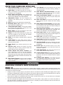
REMOVING CONTENTS FROM PACKAGING
Check shipping carton and machine for damage before unpacking. Carefully remove packaging materials, parts
and machine from shipping carton. Always check for and remove protective shipping materials around motor and moving parts. Lay
out all parts on a clean work surface.
• Compare the items to inventory figures, verify that all items are accounted for before discarding the shipping carton. Report
any missing or damaged parts, please call our Customer Care Center at 800-223-7278. Prior to tool assembly and use, read this
manual to familiarize yourself with proper assembly, maintenance and safety procedures.
• If any parts are missing, do not attempt to plug in the power cord and turn the power on. The saw should only be energized
after all parts have been located and correctly assembled.
• This saw is packaged and shipped with saw head secured in the down position, using a plastic tie. To remove the plastic tie:
push saw head down, cut plastic tie. See “Saw Head Lock Pin” in “Preparing Your Saw for Transport” section of this manual for
instructions on how to use the saw head lock pin.

10 11
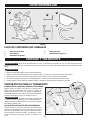
PACKAGED CONTENTS LIST
A. Delta Cruzer 26-2251
B. Blade Wrench
C. Work Clamp
D. Dust Bag
E. Support Extensions x 2 pcs
Figure 3
B
D
E
UNPACKING
Before moving/transporting your saw it is important to make sure all of the following steps have been followed to
ensure a safe condition for transportation. Failure to do so can result in serious personal injury.
• Always turn the power o and unplug saw before transporting.
• Secure power cord to avoid any snags or hang ups during transportation.
• Always lift using the strength of your legs to lift saw; never use your back muscles to lift saw.
• Do not use power On/O switch handle or power cord to lift your saw.
• Always place the saw onto a stable and level surface with clearance for handling and maneuvering.
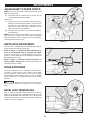
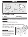
Always lock saw head in the down position before transporting
saw. To engage saw head lock pin (A): Push saw head to the
down position then push-in lock pin shown in Fig 4.
Saw Head lock pin is for storage and
transport only. This saw should never be locked in the down
position while making cuts.
A
B
Always engage the slide prevention lock (B) before
transporting this saw. To engage slide prevention lock: Push
saw head to the fully retracted position then swing the lock
link down as shown in Fig. 4.
Figure 4
MOUNTING AND TRANSPORTATION
SAW HEAD LOCK PIN
SLIDE PREVENTION LOCK
PREPARATIONS FOR TRANSPORTATION
A
C

11
MOUNTING AND TRANSPORTATION
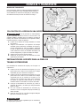
CARRY HANDLE
MOUNTING SAW TO STABLE SURFACE
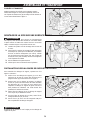
For transportation use the included carry handle (A) as shown
in Fig. 5 You may also lift using the cast-in handle cut-outs (B)
on both sides of the saw base as shown in Fig. 5
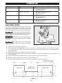
To ensure safe and accurate operation, this
saw should be mounted to a stable and level surface such as a
workbench. To mount the tool to a stable surface, refer to
Figure 6 and do the following:
1. Locate the four mounting holes in the base of the saw
C.
2. Secure the tool to the mounting surface using 3/8”
diameter machine bolts, lock washers, and hex nuts
(not included). Make sure the bolts are long enough to
accommodate the saw base, lock washers, hex nuts,
and the thickness of the workbench.
3. Tighten all four bolts securely.
4. Check to make sure that the saw is secure before
operation.
Figure 5
Figure 6
C C
B
A
Figure 7
D
E
F
G
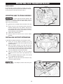
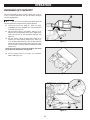
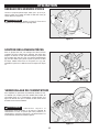
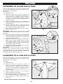
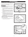
INSTALLING SUPPORT EXTENSIONS
To assemble the support extensions, refer to Figure 7 below:
1. Insert one of the support extensions (F) to the
underside of the base at the cast-in handle cut-outs (B)
shown in Figure 5.
2. Make sure support extension (F) is ush with the base
and inserted into the rounded slots of the cut-outs (B).
The rivets (G) are used to ensure the support extension
does not slide out of the base during use. Ensure these
rivets are positioned on the inside of the base.
3. Place the extension clamp (E) onto the support
extension and the screw that is pre-attached to the
base.
4. Once the extension clamp (E) is in place, screw the M8
hex nut provided (D) onto the screw.
5. Tighten the nut (D) with an M8 hex wrench to fully
secure the support extension.
Do not attempt to lift the miter saw by the
support extensions.

12 13
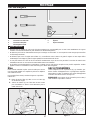
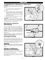
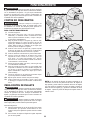
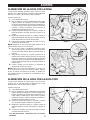
WORK CLAMP
The vertical work clamp secures the workpiece to the table to
provide more stability and keeps the workpiece from creeping
toward the saw blade.
To install the vertical work clamp, see Figure 9 and do the
following:
1. Place the clamp shaft (A) in either hole (B) on the miter
base.
2. Rotate the knob (C) on the clamp clockwise to move it
in or counter clockwise to move it out as needed.
• Do not attempt to modify this tool or create accessories not recommended for use with this tool. Any such alteration or
modication is misuse and could result in a hazardous condition.
• Do not connect to power supply until assembly is complete. Failure to comply could result in accidental starting.
• Do not start the miter saw without checking for interference between the blade and the miter fence. Damage could result to the
blade if it strikes the miter fence during operation of the saw.
• The saw can tip over if the saw head is released suddenly and the saw is not secured to a work surface. ALWAYS secure this saw
to a stable work surface before any use.
• If any parts are damaged or missing do not operate this tool until the parts are replaced. Please call Customer Care Center at
800-223-7278, for instructions.
Figure 9
A
B
C
D
A. T20 Torx Driver
B. Flat Head Drive
C. 5mm Hex Wrench
D. Square
E. Combination Square
Figure 8
E
TOOLS NEEDED
B
ASSEMBLY
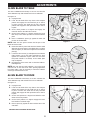
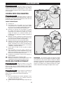
DUST BAG
The Tool includes a dust collection bag (D) that attaches over
the exhaust port on the upper blade guard. Slide the plastic
collar onto the dust exhaust port on the back of the saw head.
See Figure 10
NOTE: To remove the dust bag for emptying, simply reverse
the above procedure.
Figure 10
D
A
C

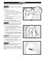
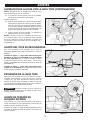
13
If inner blade washer has been removed,
replace it before placing blade on spindle. Failure to do so
could cause an accident since blade will not tighten properly.
7. Press the spindle lock button (E). See figure 13.
8. Carefully t saw blade inside the blade guard and guide
it onto the spindle, ensuring the teeth of the blade are
facing down at the front of the saw.
9. Align the double “D” ats on the blade washer (F) with
the ats on the spindle and t the washer onto the
spindle.
10. Lock the spindle by depressing the spindle lock button.
Screw on the blade bolt (D), remembering to thread it
counter clockwise. Tighten blade bolt securely using the
provided blade wrench.
Always install the blade with the blade teeth
and the arrow on the side of the blade pointing down at the
front of the saw. The direction of the blade rotation is also
stamped with an arrow on the upper blade guard.
11. Replace the blade bolt cover and tighten blade bolt
cover screw securely. Lower blade guard.
12. Raise and lower the saw arm to ensure that the arm
and blade guard move freely.
Make sure the spindle lock button is not
engaged before reconnecting saw to power source. Never
engage spindle lock button when blade is rotating.
NOTE: Some illustrations in this manual indicate only portions
of the saw. This is done in order to more clearly show key
areas and components of the saw. Never operate the saw
without all guards securely in place and in good operating
condition.
ASSEMBLY
Figure xx
Figure 13
Figure 12
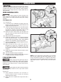
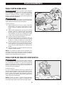
INSTALL/REMOVE/REPLACE BLADE
A 12-inch blade is the maximum blade
capacity of the saw. Larger blades will come in contact with
the blade guards.
Refer to Figure 11.
1. Make sure the saw is unplugged.
2. Raise the saw arm to the full upright position.
3. Rotate the lower blade guard (A) up. Slightly loosen the
blade bolt cover screw (B) until you can move the blade
bolt cover (C) up to expose the blade bolt (D).
Refer to Figure 12.
4. If replacing the blade, carefully rotate the old blade until
the spindle locks in place.
5. Using the supplied blade wrench, remove the blade bolt
(D) by turning it clockwise.
NOTE: The blade bolt has left-hand threads.
6. Remove only the outer blade washer (F) and the blade
(G), leaving the inner blade washer on the spindle.
Figure 11
A
B
G
F
E
C
D

14 15
OPERATION
Figure 14
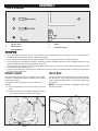
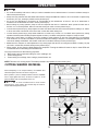
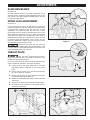
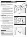
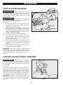
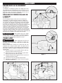
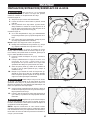
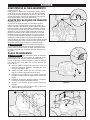
CUTTING WARPED MATERIAL
When attempting to cut warped material, the CONVEX face
should be against the fence as shown in Figure 14.
Never position a piece of warped material with the CONCAVE
face or edge against the fence, as shown in Figure 15. It will
pinch the blade near the completion of the cut.
To avoid a kickback and to avoid serious
personal injury, never position the concave edge of bowed or
warped material against the fence.
Figure 15
• Do not allow familiarity with tools to make you careless. Remember that a careless fraction of a second is sucient enough to
inict serious personal injury.
• Always wear eye protection with side shields and marked to comply with ANSI Z87.1 Failure to do so could result in objects being
thrown into your eyes, resulting in possible serious personal injury.
• Do not use any attachments or accessories not recommended by the manufacturer of this tool. The use of attachments or
accessories not recommended can result in serious personal injury.
• Before starting any cutting operation, clamp or bolt the compound miter saw to a workbench. Never operate the miter saw on
the oor or in a crouched position. Failure to heed this warning can result in serious personal injury.
• To avoid serious personal injury, always tighten the miter lock handle and bevel lock knob securely before making a cut. Failure
to do so could result in movement of the control arm or miter table while making a cut.
• To avoid serious personal injury, keep hands outside the no hands zone, at least 3 in. from blade. Never perform any cutting
operation freehand (without holding workpiece against the fence). The blade could grab the workpiece if it slips or twists.
• When using a work clamp or C-clamp to secure the workpiece, clamp workpiece on one side of the blade only. The workpiece
must remain free on one side of the blade to prevent the blade from binding in workpiece. The workpiece binding the blade will
cause motor stalling and kickback. This situation could cause an accident resulting in serious personal injury.
• NEVER move the workpiece or make adjustment to any cutting angle while the saw is running and the blade is rotating. Any slip
can result in contact with the blade causing serious personal injury.
• When cutting, do not force the blade against the workpiece. Forcing the blade will cause a drop in motor RPM and
increase the risk of overheating the saw blade tips.
You may use this tool for the following purposes:
• Bevel cutting and compound cutting for crown moldings, etc.
• Cross cutting wood
• Cross cutting for moldings, door casings, picture frames, etc.
NOTE: This saw is for cutting wood. The blade provided is acceptable for wood cutting only.

15
A
B
C
Figure 17
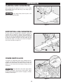
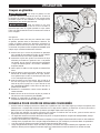
CLAMPING WIDE WORKPIECES
SUPPORTING LONG WORKPIECES
OPERATION
Figure 16
When cutting wide work pieces, such as 2 in. X 12 in., clamp
the workpiece to the work table using a work clamp (A) as
shown in Figure 16.
Keep clamps away from the path of the
blade and blade guard assembly.
In most cases the included table extensions (workpiece
supports) will be sufficient to support longer workpieces. If
these are not long enough, the workpiece should be supported
further out from the saw. Additional support (B) may be used
to make the workpiece lay flat on the saw table. Use the
included work clamp or a C-clamp (C) to secure the workpiece
to the miter saw table. See Figure 17.
Figure 18
POWER SWITCH LOCK
To prevent any unauthorized person from operating this saw,
a padlock (not included) should be installed into the lock hole
located on the power switch, as shown in Figure 18. Be sure
padlock is fully closed and locked before leaving this saw
unattended.
Always disconnect the power supply before
installing or removing a lock onto the power switch. Failure
to do so could cause the power switch to engage by accident,
resulting in serious injury.

16 17
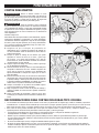
NON-SLIDING CUTS
Before turning the saw power ON, check to
make sure saw head and blade will not make contact with the
provided work clamp or fence during the cutting operation.
Position the work clamp and fence to avoid contact with the
miter saw head.
FOR CROSS CUTS
1. See Figure 19
2. To use this saw as a traditional, non-sliding, miter saw:
slide the saw head into the fully retracted position and
engage the slide prevention lock
3. Loosen the miter lock knob (A), use your thumb to push
in the miter detent lock button (B), and set the miter
arm angle to 0 degrees. Use the miter scale (C) and
indicator (D) to locate the 0 degree miter position.
4. Release the miter detent button (B) and tighten the
miter lock knob (A). Check that saw head is securely
locked into position.
5. Raise the saw head to its UP position.
6. Position the workpiece so that it is securely supported
by the saw table and fence. If the board is warped,
read and follow the instructions under “Cutting Warped
Material” in the “Operation” section of this manual.
7. Secure the workpiece to the table and against the fence,
using the provided clamp.
8. Before turning the power switch ON, perform a
simulated cut to check your cut alignment. Also check
to make sure the blade will not come into contact with
the provided work clamp or anything other than the
workpiece.
9. Engage the power ON switch. Allow the blade to reach
maximum speed.
10. Lower the saw blade through the workpiece.
11. Disengage the power switch and allow blade to come to
a complete stop before raising the saw head.
Figure 19
OPERATION
FOR MITER CUTS
Figure 20
B
LOCK
UNLOCK
F
G
LOCK
UNLOCK
Always engage the slide prevention lock
before making any non-sliding cuts. Failure to engage this lock
could result in saw head movement during the cutting
operation.
Before turning the saw power ON, check to
make sure saw head and blade will not make contact with the
provided work clamp or fence during the cutting operation.
Position the work clamp and fence to avoid contact with the
miter saw head.
Always tighten the miter lock knob (E) before
any cutting operation. Failure to do so may result in serious
personal injury.
See Figure 20
1. Follow Operation instructions “For Cross-Cuts” in
previous manual section. Include the following
adjustments before cutting.
2. Rotate miter arm to required miter angle other than 0
degrees.
E
A
C
D
NOTE: If your required miter angle position is not provided
with one of the positive stop miter detent positions; you can
use the miter detent override (G). To engage the miter detent
override, push in the miter detent button (F) and push in the
miter detent override. Tighten the miter lock knob before
cutting.

17
FOR BEVEL CUTS
OPERATION
LOCK
LOCK
UNLOCK
UNLOCK
Figure 22
Figure 21
Before turning the saw power ON, check to
make sure saw head and blade will not make contact with the
provided work clamp or fence during the cutting operation.
Position the work clamp and fence to avoid contact with the
miter saw head.
Always lock the bevel lock handle before
any cutting operation. Failure to do so may result in serious
personal injury.
See Figure 21
1. Follow Operation instructions “For Cross-Cuts” in
previous manual section. Include the following
adjustments before cutting.
2. Loosen fence lock knob (A) on left and right side, and
slide adjustable fence (B) to allow proper spacing for
bevel cuts. Once proper spacing is set, tighten fence
lock knob
3. Lift the bevel lock handle (C)
4. While rmly supporting the saw head with one hand,
push back the bevel latch lever (D) and swing the saw
head left or right to the required bevel angle.
5. If you are using one of the bevel detent positions, check
to make sure the bevel latch lever and bevel detent
locks into the positive stop plate.
6. Push down the bevel lock handle to lock bevel position.
NOTE: If your required bevel angle position is not provided
with one of the positive stop bevel detent position; you can
lock the bevel position at any location using the bevel lock
handle (C).
FOR COMPOUND MITER CUTS
Before turning the saw power ON, check to
make sure saw head and blade will not make contact with the
provided work clamp or fence during the cutting operation.
Position the work clamp and fence to avoid contact with the
miter saw head.
See Figure 22
A compound miter cut uses a combination of a miter angle
adjustment and bevel angle adjustment. Use the instructions
above “For Miter Cuts” and “For Bevel Cuts” to set your
bevel and miter angle before performing the “For Cross-cuts”
operation instructions above.
NOTE: The miter angle and bevel angle are dependent upon
each other. If you adjust one of these it will change the other.
Always check both angles after making any adjustments.
A
B
D
C

18 19
1
2
OPERATION
Figure 23
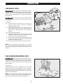
SLIDE CUTS
A slide cut should never be performed by
pulling the saw toward you. Due to the blade rotation
direction, this can cause the saw blade to climb over the
workpiece and towards the operator. Failure to follow this
warning could result in serious personal injury.
Before turning the saw power ON, check to
make sure saw head and blade will not make contact with the
provided work clamp or fence during the cutting operation.
Position the work clamp and fence to avoid contact with the
miter saw head.
See Figure 23
To use this saw to make slide cuts follow the instructions
below. Slide cuts must only be performed by pushing the saw
blade away from you and toward the back of the saw, stopping
at the fully RETRACTED position after each cut. See warning
above.
A
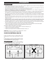
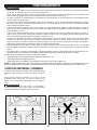
• The two edges of the molding that contact the ceiling and the wall are at angles that, when added together, equal exactly 90°.
Most crown molding has a top rear angle (the section that ts at against the ceiling) of 52° and a bottom rear angle (the
section that ts at against the wall) of 38°.
• To accurately cut crown molding for a 90° inside or outside corner, lay the molding with its broad back surface at on the miter
table and against the fence.
• The angles for crown moldings must be very precise. The bevel and miter angles are interdependent; changing one angle
changes the other angle as well.
• Since it is very easy for the work piece to shift, all settings should rst be tested on scrap molding. Also most walls do not have
angles of exactly 90°; therefore, you will need to ne-tune your settings.
• When cutting crown molding the bevel angle should be set at 33.85°.
• The miter angle should be set at 31.62° either right or left, depending on the desired cut for the application. See the chart
below for correct angle settings and correct positioning of crown molding on the work table.
TIPS FOR CUTTING CROWN MOLDING
1. Check to make sure the slide prevention lock (B) and head
lock pin (A) is not engaged. Raise the saw head to its UP
position.
2. Position the workpiece so that it is securely supported by
the saw table and fence. If the board is warped, read and
follow the instructions under “Cutting Warped Material” in
the “Operation” section of this manual.
3. Secure the workpiece to the table and against the fence,
using the provided clamp.
4. Before turning the power switch ON, perform a simulated
cut to check your cut alignment. Also check to make sure
the blade will not come into contact with the provided
work clamp or anything other than the workpiece.
5. Before turning the power switch ON, pull the saw arm
towards you until the blade is beyond the front edge
of your workpiece or until the saw arm is in the fully
EXTENDED position. The saw head should be in the full UP
position.
6. Engage the power ON switch. Allow the blade to reach
maximum speed.
7. Lower the saw blade through the workpiece and push the
saw head towards the fully RETRACTED position.
8. Disengage the power switch and allow blade to come to a
complete stop before raising the saw head.
Figure 24
B

19
OPERATION
Figure 25
Figure 26
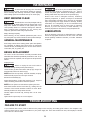
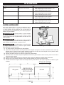
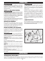
AUXILIARY FENCE
For cutting certain workpieces, you may require a larger fence
surface area to accommodate the workpiece. The auxiliary
fence should be made using 3/4” thick wood. Use the holes
which are pre-drilled in the fence to attach an auxiliary fence.
Never use auxiliary fence which interferes or
makes contact with saw head. Always check for clearance
between auxiliary fence and saw head before making cuts.
To make slide cuts using an auxiliary fence, a
notch must be cut out in the auxiliary fence prior to attaching
to saw fence.
The auxiliary fence can only be used with the
0 degree bevel angle. Remove the auxiliary fence before
making a bevel cut.
1. See gure 26 for auxiliary fence dimensions.
2. Place auxiliary fence wood against miter saw fence. See gure 25. The maximum height for this wood must not exceed
6.5”. Check to make sure auxiliary fence does make contact with saw head, check with saw head in the full DOWN and fully
RETRACTED position.
3. Mark the hole locations on the backside of the auxiliary fence board.
4. Drill the marked hole locations all the way through the auxiliary fence. Countersink the drilled holes on the front side of your
auxiliary fence board.
5. Fasten the auxiliary fence using at head screws. Secure from behind using at washers and nuts.
6. Make a full depth cut through the auxiliary fence, to create the blade slot.
7. The notch shown in gure 26 must be cut out in order to make slide cuts using the auxiliary fence.
Bevel Angle Setting Type of Cut Steps
33.85° Left side, inside corner 1. Top edge of molding against fence
2. Miter table set right 31.62°
3. Save left end of cut
33.85° Right side, inside corner 1. Bottom edge of molding against fence
2. Miter table set left 31.62°
3. Save left end of cut
33.85° Left side, outside corner 1. Bottom edge of molding against fence
2. Miter table set left 31.62°
3. Save right end of cut
33.85° Right side, outside corner 1. Top edge of molding against fence
2. Miter table set right 31.62°
3. Save right end of cut

20 21
C
Figure 27
Figure 29
B
A
OPERATION
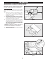
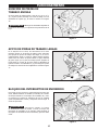
INCREASE CUT CAPACITY
This saw is designed to allow for large capacity cuts up to (2”
x 18”). In order to make these cuts you will need to configure
your saw appropriately.
Do not use an auxiliary table board which will
not fully support the workpiece during cutting operation.
1. Loosen the fence lock knob (A). Slide the upper
(adjustable) fence (B) completely out of its track and set
to the side. See Figure 27.
2. Flip the support tabs (C) into position. Tabs (C) are on
both the left and right sides of the lower (xed) fence.
These will function as your workpiece backstop. See
Figure 29.
3. You will need to add an auxiliary table board (D) to
support your large capacity workpiece (E). Place a 2”
x 14” auxiliary table board (D) onto the saw table and
against the lower (xed) section of the saw fence. Make
sure the board is securely positioned against the lower
(xed) fence.
NOTE: Use wood screws to secure the auxillary table board
(D) to the lower (xed) fence. See Figure 28.
4. Use the support tabs (C) to secure your workpiece
before making any cuts
LOOSEN
TIGHTEN
C
E
D
Figure 28
La page est en cours de chargement...
La page est en cours de chargement...
La page est en cours de chargement...
La page est en cours de chargement...
La page est en cours de chargement...
La page est en cours de chargement...
La page est en cours de chargement...
La page est en cours de chargement...
La page est en cours de chargement...
La page est en cours de chargement...
La page est en cours de chargement...
La page est en cours de chargement...
La page est en cours de chargement...
La page est en cours de chargement...
La page est en cours de chargement...
La page est en cours de chargement...
La page est en cours de chargement...
La page est en cours de chargement...
La page est en cours de chargement...
La page est en cours de chargement...
La page est en cours de chargement...
La page est en cours de chargement...
La page est en cours de chargement...
La page est en cours de chargement...
La page est en cours de chargement...
La page est en cours de chargement...
La page est en cours de chargement...
La page est en cours de chargement...
La page est en cours de chargement...
La page est en cours de chargement...
La page est en cours de chargement...
La page est en cours de chargement...
La page est en cours de chargement...
La page est en cours de chargement...
La page est en cours de chargement...
La page est en cours de chargement...
La page est en cours de chargement...
La page est en cours de chargement...
La page est en cours de chargement...
La page est en cours de chargement...
La page est en cours de chargement...
La page est en cours de chargement...
La page est en cours de chargement...
La page est en cours de chargement...
La page est en cours de chargement...
La page est en cours de chargement...
La page est en cours de chargement...
La page est en cours de chargement...
La page est en cours de chargement...
La page est en cours de chargement...
La page est en cours de chargement...
La page est en cours de chargement...
La page est en cours de chargement...
La page est en cours de chargement...
La page est en cours de chargement...
La page est en cours de chargement...
-
 1
1
-
 2
2
-
 3
3
-
 4
4
-
 5
5
-
 6
6
-
 7
7
-
 8
8
-
 9
9
-
 10
10
-
 11
11
-
 12
12
-
 13
13
-
 14
14
-
 15
15
-
 16
16
-
 17
17
-
 18
18
-
 19
19
-
 20
20
-
 21
21
-
 22
22
-
 23
23
-
 24
24
-
 25
25
-
 26
26
-
 27
27
-
 28
28
-
 29
29
-
 30
30
-
 31
31
-
 32
32
-
 33
33
-
 34
34
-
 35
35
-
 36
36
-
 37
37
-
 38
38
-
 39
39
-
 40
40
-
 41
41
-
 42
42
-
 43
43
-
 44
44
-
 45
45
-
 46
46
-
 47
47
-
 48
48
-
 49
49
-
 50
50
-
 51
51
-
 52
52
-
 53
53
-
 54
54
-
 55
55
-
 56
56
-
 57
57
-
 58
58
-
 59
59
-
 60
60
-
 61
61
-
 62
62
-
 63
63
-
 64
64
-
 65
65
-
 66
66
-
 67
67
-
 68
68
-
 69
69
-
 70
70
-
 71
71
-
 72
72
-
 73
73
-
 74
74
-
 75
75
-
 76
76


Delta 26-2251 Le manuel du propriétaire
- Catégorie
- Scies à onglet
- Taper
- Le manuel du propriétaire
- Ce manuel convient également à
dans d''autres langues
- English: Delta 26-2251 Owner's manual
- español: Delta 26-2251 El manual del propietario