ALARM COM ADC-V724 1080p Outdoor WiFi Camera Guide d'installation
- Taper
- Guide d'installation

1080p Outdoor
Wi-Fi Camera with
Two-Way Audio
Installation Guide
ADCV724


1
Pre-installation checklist
• ADC-V724 camera (included)
• AC power adapter (included)
• Wi-Fi (2.4 or 5 GHz) connection to broadband Internet
(Cable, DSL, or Fiber Optic) Internet
• A computer, tablet, or smartphone with Wi-Fi is required if the
router does not have the Wi-Fi Protected Setup (WPS) feature.
There are two options for connecting the V724 to the Wi-Fi
network: Access Point (AP) mode or Wi-Fi Protected Setup
(WPS) mode. Use WPS mode if you have easy access to the
customer’s router and the router has the WPS feature enabled.
Note that some Internet Service Providers disable the
WPS feature on customer routers. AP mode is the most
reliable method for installing this device.

2
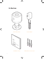
In the box
ADC-V724 camera Power adapter
Installation Guide Wall anchors & screws (x3)

3
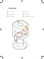
Overview
❶ Status LED
❷ SD Card Door
❸ SD Card Slot
❹ Speaker
❺ Microphone
❻ WPS/Reset button
❹
❻
❷
❺
❶
❸

4
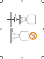
Rubber Plug
A rubber plug has been included with your ADC-V724
at the base of the mount. This rubber plug should only
be used if you are mounting directly over a hole in the
wall. The rubber plug will provide a seal to prevent water
from entering the hole in the wall behind the camera.
In all other installations, please remove the rubber plug.
Removing the rubber plug will allow you to route the power
cable through the mouse hole without bending or breaking
the cable.

5

6
Installation
AP Mode (recommended)
To ensure sufficient Wi-Fi signal, complete these steps with
the camera near its final location but prior to mounting.
1. Connect the camera’s AC power adapter and plug it into
a non-switched outlet.
2. The camera’s LED will begin to blink white. If the LED is not
white after two minutes, hold down the WPS/Reset button
and release when the LED begins to blink white (about 6 seconds).
3. On an Internet-enabled device, connect to the Wi-Fi network
ADC-V724 (XX:XX:XX) where XX:XX:XX is the last six characters
of the ADC-V724’s MAC address, which is located on the camera
or on the packaging.
4. On the same device, open a web browser and enter http://
v724install in the URL field. Follow the on-screen instructions
to add the ADC-V724 to the Wi-Fi network. The LED will briefly
turn red before blinking green. The LED will be solid green when
the connection is complete.
5. Add the device to the account by either selecting the account in
MobileTech or by using a web browser and entering the following
URL: www.alarm.com/addcamera (you will need the customer
user name and password).
6. Select the camera from the video device list or enter its MAC
address to begin adding the camera. The MAC address is
located on the camera or on the packaging.
7. Follow the on-screen instructions to finish adding the camera.

7
You can now power down the camera and install it in its final
location using the included hardware. You may configure camera
settings from the Customer Website.
WPS Mode (alternate)
To ensure sufficient Wi-Fi signal, complete these steps with
the camera near its final location but prior to mounting.
1. Connect the camera’s AC power adapter and plug it into
a non-switched outlet.
2. After the startup process is complete (the camera’s LED will
be blinking white), hold down the WPS/Reset button and
release when the LED begins to blink blue (about 3 seconds).
3. Activate WPS mode on the router. The camera will begin to
connect to the Wi-Fi network. The LED will be solid green
when the connection is complete.
4. Add the device to the account by either selecting the account in
MobileTech or by using a web browser and entering the following
URL: www.alarm.com/addcamera (you will need the customer
user name and password).
5. Select the camera from the video device list or enter its MAC
address to begin adding the camera. The MAC address is
located on the camera or on the packaging.
6. Follow the on-screen instructions to finish adding the camera.
You can now power down the camera and install it in its final
location using the included hardware. You may configure camera
settings from the Customer Website.

8
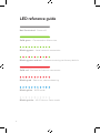
LED reference guide
Not illuminated - Power off
Solid green - Connected to Alarm.com
Blinking green - Local network connection
Blinking green and red - Camera resetting to factory default
Solid red - No local or Internet connection
Blinking red - Power on, camera booting
Blinking blue - WPS mode
Blinking white - Wi-Fi Access Point mode

Troubleshooting
1. If you have issues connecting the camera to the account,
power cycle the camera and try again.
2. If issues persist, reset the camera to factory defaults.
Press and hold the WPS/Reset button until the LED is flashing
green and red (about 15 seconds), then release the button.
The camera will reboot to factory default.
If the camera was previously installed to an Alarm.com account,
it will need to be deleted before it can be installed again.
Prolonged exposure to sunlight in extreme conditions may
impact the camera’s performance. The optimal installation
location is in a shaded area such as under an eave.
Questions?
Visit: answers.alarm.com or contact your service provider
9

1010
Notices
Federal Communication Commission
interference statement
This equipment has been tested and found to comply with the limits for a
Class B digital device, pursuant to part 15 of the FCC Rules. These limits are designed to
provide reasonable protection against harmful interference in a residential installation.
This equipment generates, uses and can radiate radio frequency energy and, if not
installed and used in accordance with the instructions, may cause harmful interference to
radio communications. However, there is no guarantee that interference will not occur in a
particular installation. If this equipment does cause harmful interference to radio or
television reception, which can be determined by turning the equipment off and on, the
user is encouraged to try to correct the interference by one or more of the following
measures:
• Reorient or relocate the receiving antenna.
• Increase the separation between the equipment and receiver.
• Connect the equipment into an outlet on a circuit different from that to
which the receiver is connected.
• Consult the dealer or an experienced radio/TV technician for help. Changes or
modifications not expressly approved by the party responsible for compliance could void
the user’s authority to operate this equipment.

FCC Caution
Any changes or modifications not expressly approved by the party responsible
for compliance could void the user’s authority to operate this equipment.
This device complies with Part 15 of the FCC Rules. Operation is subject to the
following two conditions:
1. This device may not cause harmful interference, and
2. This device must accept any interference received, including interference that
may cause undesired operation.
This device and its antenna(s) must not be co-located or operating in conjunction
with any other antenna or transmitter.
For product available in the USA/Canada market, only channel 1~11 can be operated.
Selection of other channels is not possible.
FCC Radiation Exposure Statement:
This equipment complies with FCC radiation exposure limits set forth for an uncontrolled
environment. This equipment should be installed and operated with minimum distance
20cm between the radiator & your body.
ISED Caution
This device contains licence-exempt transmitters(s)/receiver(s) that comply with
Innovation, Science and Economic Development Canada’s licence-exempt RSS(s).
Operation is subject to the following two conditions:
1. This device may not cause interference.
2. This device must accept any interference, including interference that may
cause undesired operation of the device.
L’émetteur/récepteur exempt de licence contenu dans le présent appareil est
conforme aux CNR d’Innovation, Sciences et Développement économique Canada
applicables aux appareils radio exempts de licence. L’exploitation est autorisée
aux deux conditions suivantes:
1. L’appareil ne doit pas produire de brouillage;
2. L’appareil doit accepter tout brouillage radioélectrique subi, même si le brouillage
est susceptible d’en compromettre le fonctionnement.
11

This radio transmitter [IC: 9111A-V724] has been approved by Innovation, Science and
Economic Development Canada to operate with the antenna types listed below, with
the maximum permissible gain indicated. Antenna types not included in this list that
have a gain greater than the maximum gain indicated for any type listed are strictly
prohibited for use with this device.
Le présent émetteur radio [IC: 9111A-V724] a été approuvé par Innovation, Sciences et
Développement économique Canada pour fonctionner avec les types d’antenne énumérés
ci dessous et ayant un gain admissible maximal. Les types d’antenne non inclus dans cette
liste, et dont le gain est supérieur au gain maximal indiqué pour tout type figurant sur la
liste, sont strictement interdits pour l’exploitation de l’émetteur.
The device for operation in the band 5150-5250 MHz is only for indoor use to reduce the
potential for harmful interference to co-channel mobile satellite systems.
Les dispositifs fonctionnant dans la bande 5150-5250 MHz sont réservés uniquement
pour une utilisation à l’intérieur afin de réduire les risques de brouillage préjudiciable
aux systèmes de satellites mobiles utilisant les mêmes canaux.
12
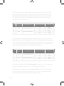
No. Antenna
Type Model Number Antenna Gain(dBi) Remark
1FPCB RFFPA301205IMLB401 3.94 2.4GHz
5.3 5GHz
2FPCB RFFPA301213IMLB401 3.78 2.4GHz
4.28 5GHz
No. Antenna
Type Model Number Antenna Gain(dBi) Remark
1FPCB RFFPA301205IMLB401 3.94 2.4GHz
5.3 5GHz
2FPCB RFFPA301213IMLB401 3.78 2.4GHz
4.28 5GHz

IMPORTANT NOTE:
IC Radiation Exposure Statement:
This equipment complies with IC RSS-102 radiation exposure limits set forth for an
uncontrolled environment. This equipment should be installed and operated with
minimum distance 20cm between the radiator & your body.
Cet équipement est conforme aux limites d’exposition aux rayonnements IC établies
pour un environnement non contrôlé. Cet équipement doit être installé et utilisé avec
un minimum de 20cm de distance entre la source de rayonnement et votre corps.
The transmitter module may not be co-located with any other transmitter or antenna.
Le module émetteur peut ne pas être coïmplanté avec un autre émetteur ou antenne.
CAN ICES-3 (B)/NMB-3(B)
The Country Code Selection feature is disabled for products marketed in the US/Canada.
For product available in the USA/Canada market, only channel 1~11 can be operated.
Selection of other channels is not possible.
Pour les produits disponibles aux États-Unis / Canada du marché, seul le canal 1 à 11
peuvent être exploités. Sélection d’autres canaux n’est pas possible.
13

8281 Greensboro Drive
Suite 100
Tysons, VA 22102 © 2021 Alarm.com. All rights reserved.
210310 | Made in China.
-
 1
1
-
 2
2
-
 3
3
-
 4
4
-
 5
5
-
 6
6
-
 7
7
-
 8
8
-
 9
9
-
 10
10
-
 11
11
-
 12
12
-
 13
13
-
 14
14
-
 15
15
-
 16
16


ALARM COM ADC-V724 1080p Outdoor WiFi Camera Guide d'installation
- Taper
- Guide d'installation
dans d''autres langues
Autres documents
-
Scosche BTFM3B Manuel utilisateur
-
Haike AF001 Manuel utilisateur
-
Denso UR40-H-ERU Manuel utilisateur
-
HID iClass SE Le manuel du propriétaire
-
Furbo Mini Dog Camera Mode d'emploi
-
ADT RC845 Guide d'installation
-
Comtrend Corporation WAP-5903 Manuel utilisateur
-
Synology WRX560 Router Manuel utilisateur
-
Brickcom OB-300N Series Hardware User Manual
-
 SkyBell Trim II Pro Mode d'emploi
