Burkert Type 2000 Guide de démarrage rapide
- Taper
- Guide de démarrage rapide

Quickstart
English Deutsch Français
Type 2000
2/2-Way Angle Seat Valve
2/2-Wege Schrägsitzventil
Vanne à siège incliné 2/2 voies

We reserve the right to make technical changes without notice.
Technische Änderungen vorbehalten.
Sous réserve de modifications techniques.
© Bürkert Werke GmbH & Co. KG, 201 - 2017
Operating Instructions 1706/0_EU-EN_008 / Original DE

3
Quickstart
1 QUICKSTART
..................................................................................................3
2 SYMBOLS
.........................................................................................................3
3 INTENDED USE .............................................................................................4
4 BASIC SAFETY INSTRUCTIONS ..........................................................4
5 CONTACT ADDRESSES ...........................................................................5
6 TECHNICAL DATA ........................................................................................5
7 ASSEMBLY
.......................................................................................................7
8 START-UP
.........................................................................................................9
9 DISASSEMBLY
............................................................................................10
10 TRANSPORTATION, STORAGE, DISPOSAL ................................10
If you have any questions, contact your Bürkert sales office.
2 SYMBOLS
Warning to prevent death or serious injuries:
DANGER!
Warns of an immediate danger!
WARNING!
Warns of a potentially dangerous situation!
Warning to prevent moderate or minor injuries:
CAUTION!
Warns of a possible danger!
NOTE!
Warns of damage to property!
Important tips and recommendations.
Refers to information in these operating instructions or in
other documentation.
▶ designates instructions for risk prevention.
→ designates a procedure which you must carry out.
1 QUICKSTART
The quickstart comprises important information.
▶ Carefully read the quickstart and observe any safety information.
▶ The quickstart must be available to every user.
▶ The liability and warranty for Type 2000 do not apply if the quick-
start instructions are not observed.
The quickstart illustrates the installation and commissioning of the
equipment by way of example. A detailed description of the equipment
can be found in the operating instructions for Type 2000 on the Internet
at: www.burkert.com
english
Type 2000

4
Intended use
3 INTENDED USE
Incorrect use of the Type 2000 can be dangerous to people,
nearby equipment and the environment.
Angle seat valve Type 2000 is designed to control the flow-rate of
liquid and gaseous media.
▶ In the potentially explosion-risk area the type 2000 may be used
only according to the specification on the separate Ex type
label. For use observe the additional information enclosed with
the device together with safety instructions for the explosion-risk
area.
▶ Devices without a separate Ex type label may not be used in a
potentially explosive area.
▶ Observe the permitted application conditions for using the
equipment.
▶ Operate only when in perfect condition and pay attention to cor-
rect storage, transportation, installation and operation.
▶ Only supply fluids into the media connections that are specified
in section “6 Technical data”.
▶ Do not make any internal or external changes to Type 2000.
▶ Only trained technicians may perform installation and mainte-
nance work.
▶ After an interruption in the power supply, ensure that the pro-
cess is restarted in a controlled manner.
▶ Do not use in vibration-prone areas.
▶ Do not apply a mechanical load to the device.
▶ Observe the general regulations of technology.
3.2 Restrictions
If exporting the system/device, observe any existing restrictions.
4 BASIC SAFETY INSTRUCTIONS
These safety instructions do not make allowance for any
• contingencies and events which may arise during the installation,
operation and maintenance of the devices.
• local safety regulations – the operator is responsible for observing
these regulations, also with reference to the installation personnel.
Danger – high pressure!
▶ Turn off the pressure and vent the lines before loosening lines
or valves.
Risk of electric shock!
▶ Before reaching into the device or the equipment, switch off the
power supply and secure to prevent reactivation!
▶ Observe applicable accident prevention and safety regulations
for electrical equipment!
Risk of burns!
The surface of the equipment can become hot during long-term
operation.
▶ Do not touch Type 2000 with bare hands.
To prevent injuries/damage:
▶ Secure system/equipment from unintentional activation.
english
Type 2000

5
Contact addresses
5 CONTACT ADDRESSES
Germany
Bürkert Fluid Control Systems
Sales Center
Christian-Bürkert-Str. 13-17
74653 Ingelfingen
Germany
Tel. + 49 (0) 7940 - 10 91 111
Fax + 49 (0) 7940 - 10 91 448
Email: [email protected]
International
Contact addresses can be found on the Internet at: www.burkert.com
6 TECHNICAL DATA
6.1 Conformity
The Type 2000 is compliant with the EC Directives according to the
EC Declaration of Conformity.
6.2 Standards
Refer to the EC type approval test certificate and/or the EC Decla-
ration of conformity for the applicable standards verifying conformity
with the EC directives.
6.3 General technical data
Control medium: neutral gases, air
Flow media: water, alcohols, oils, fuels, hydraulic liquid,
saline solutions, lyes, organic solvents, steam
Materials and connections: see data sheet
Installation position: defined by the user, preferably with actuator
facing up
6.4 Control function
A
P
A
Closed by spring force in rest position
B
P
A
Opened by spring force in rest position
I
P
A
Actuating function via reciprocal pressurization
english
Type 2000

6
Technical data
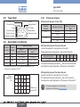
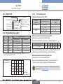
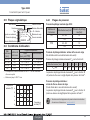
6.5 Type label
Flow 1 2
2000 A 50,0 NBR RG
Made in Germany
00182076
W1X LU
G 2 P
med 16 bar
Pilot 1,6 - 10 bar
R
"R": ModelType
Control pressure
Control function
Identification number
Direction of flow Orifice
Sealing material
Body material
Nominal pressure
Connection type
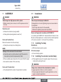
6.6 Application conditions
Actuator
size [mm]
Actuator
material
Temperature rang
Medium
(with PTFE seal)
Ambient temper-
ature
1)
40 – 63 PA -10 to see below -10 to see below
80 – 125 PA -10 to +180°C -10 to +60°C
40 – 80 PPS -10 to +180°C +5 to +140°C
125 PPS -10 to +180°C +5 to +90°C
2)
1)
Including the pilot valve, the max. ambient temperature is +55°C.
2) Briefly up to a maximum of 140°C.
Medium tem-
perature [°C]
Ambient
temperature
[°C]
100 120 140 160 180 200
70
60
50
40
30
20
∅ 63
∅ 50
∅ 40
6.6.1 Pressure ranges
Maximum pilot pressure of Type 2000:
Actuator
material
Actuator size [mm]
Max. pilot pressure
[bar]
PA 40 - 80 10
125 7
PPS 40 - 80 10
125 7
Minimum pilot pressure: flow below the seat
(medium flow against the closing direction of the valve)
Required minimum pilot pressure P
min
with control function A:
Actuator size [mm] 40 50 63 80 100 125
P
min
[bar]
4.0 3.9 4.5 5.0 4.4 3.2
The required minimum pilot pressure P
min
with control function B and I
(flow below the seat) is dependent on the pressure of the medium
3)
.
Minimum pilot pressure: flow above the seat
(medium flow with the closing direction of the valve)
The required minimum pilot pressure P
min
with control function A
(flow above the seat) is dependent on the pressure of the medium
3)
.
3) The pressure diagrams are in the operating
instructions on the Internet: www.burkert.com
english
Type 2000

7
Assembly
7 ASSEMBLY
DANGER!
Risk of injury from high pressure in the system.
▶ Before loosening lines or valves, turn off the pressure and vent
the lines.
Preparatory work
→ Observe flow direction (see type label).
→ Clean pipelines (sealing material, swarf, etc.).
Devices with welded body
Remove the actuator from the valve body:
→ Clamp the valve body into a holding fixture.
NOTE!
Damage to the seat seal or the seat contour!
→ Open the valve for control functions A and I: Pressurize the
lower pilot air port with compressed air (5 bar).
→ Place a suitable open-end wrench on the wrench flat of the nipple.
→ Unscrew the actuator off the valve body.
Devices with threaded body:
→ Only disassemble the actuator if required by the customer.
7.1 Installation
WARNING!
Risk of injury from improper installation!
Damaged parts or incorrect tightening torques can cause leaks on
the equipment.
▶ Use an open-end wrench for the assembly.
▶ Observe the tightening torque (see torque table).
Devices with approval in accordance with DIN EN 161
In accordance with DIN EN 161 "Automatic Shut-off Valves for Gas
Burners and Gas Appliances", a strainer must be installed upstream
of the valve to prevent a 1 mm test pin from penetrating.
7.1.1 Installing the body
Welded body:
→ Weld valve body in pipeline system.
Other body designs:
→ Connect body to pipeline.
7.1.2 Installing the actuator (welded body)
→ Check graphite seal and, if required, replace. Fully remove any
residue when replacing the seal.
WARNING!
Danger due to lubricants that contaminate the medium!
In oxygen applications there is a risk of an explosion!
▶ Only use approved lubricants for specific applications, such as
oxygen or analytical applications.
english
Type 2000

8
Assembly
→ Lubricate the nipple thread before reinstalling the actuator
(e.g. with Klüberpaste UH1 96-402 produced by Klüber).
Graphite seal
NOTE!
Damage to the seat seal or the seat contour!
→ Open the valve for control functions A and I: Pressurize the
lower pilot air port with compressed air (5 bar).
→ Observe the tightening torque when screwing the actuator into
the valve body (see table).
Orifice (DN) 15 20 25 32-40 50-65
Tightening torque ± 3 [Nm]
45 50 60 65 70
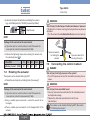
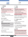
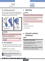
7.2 Rotating the actuator
The actuator can be rotated infinitely by 360°.
→ Clamp the valve body into a holding fixture (if necessary).
NOTE!
Damage to the seat seal or the seat contour!
→ Open the valve for control functions A and I: Pressurize the
lower pilot air port with compressed air (5 bar).
→ Using a suitable open-end wrench, counter the wrench flat on
the nipple.
→ Place a suitable open-end wrench on the hexagonal bolt of the
actuator.
WARNING!
Risk of injury from discharge of medium and release of pressure!
If the direction of rotation is wrong, the body interface may become
detached.
▶ Turn the actuator in a clockwise direction (as seen from above).
Open-end wrench for
securing the nipple
Open-end wrench
for rotating the
actuator
7.3 Connecting the control medium
DANGER!
Risk of injury from high pressure in the system!
▶ Turn off the pressure and vent the lines before loosening lines or
valves.
WARNING!
Risk of injury from unsuitable hoses!
▶ Use only hoses which are authorized for the indicated pressure
and temperature range.
▶ Observe the data sheet specifications from the hose
manufacturers.
The actuator can be rotated infinitely by 360°. See section
“7.2 Rotating the actuator”.
english
Type 2000

9
Start-Up
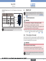
Control air hose: Use size 1/4" or 1/8" (actuator ø 40 mm) control
air hoses.
Control
function
Pilot air port
Top
Bottom
Pilot air
port
Top Bottom
A
B
I
Closes Opens
the valve
Aggressive environment: discharge free pilot air ports via a
hose into a neutral atmosphere.
8 START-UP
▶ Observe the type label specifications and information on
pressure and temperature values in section “6 Technical
data”.
8.1 Control pressure
WARNING!
For control function I – Danger if control pressure fails!
If the pressure fails, no defined position is reached.
▶ For a controlled restart, initially pressurize the equipment with
control pressure and then connect the medium.
→ Set the control pressure according to the type label specifica-
tions (section “6”) and flow direction (section “8.2” and “8.3”).
8.2 Flow above the seat
Control function A, CFA: closes by spring force with the medium flow.
The medium pressure supports the closure and seal of the valve seat.
The valve is opened by the control pressure.
WARNING!
Risk of injury due to water hammer!
A closing shock can cause lines and the equipment to burst.
▶ Only use valves with the flow above the seat for gaseous media.
To ensure complete opening, the minimum control pressure
must be used!
english
Type 2000

10
Disassembly
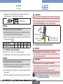
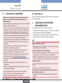
8.3 Flow below the seat
Control function A, CFA: closes by spring force against the medium flow.
Control function B, CFB: closes with the control pressure against the
medium flow. The medium pressure supports the opening of the valve.
CFA/CFI
CFB/CFI
Flow below the seat (closing
against the medium)
Flow above the seat (closing
with the medium)
CFA
WARNING!
Seat leaks caused by the minimum control pressure being too
low (on CFB and CFI) or the medium pressure being too high!
▶ Observe the minimum control pressure and medium pressure
(see “6.6.1 Pressure ranges”).
8.4 Maintenance work
→ Complete a visual inspection of the equipment once a year. Shorter
maintenance intervals may be recommended depending on the
operating conditions.
Wear parts: seals and swivel plate.
→ In the event of a leak, replace the relevant wear part.
The maintenance and repair instructions are available on the
Internet: www.burkert.com
9 DISASSEMBLY
DANGER!
Risk of injury from discharge of medium and pressure!
It is dangerous to remove a device which is under pressure due to
the sudden release of pressure or discharge of medium.
▶ Before removing a device, switch off the pressure and vent the lines.
Procedure:
→ Loosen pneumatic connection.
→ Remove device.
10 TRANSPORTATION, STORAGE,
DISPOSAL
NOTE!
Transport and storage damage!
▶ Protect the device against moisture and dirt in shock-resistant
packaging during transportation and storage.
▶ Permitted storage temperature: -20 – +65°C.
Damage to the environment caused by device components
contaminated with media.
▶ Ensure the device and packaging are disposed of in an environ-
mentally sound manner!
english
Type 2000

11
Disassembly
english
Type 2000

12
Der Quickstart
1 DER QUICKSTART ....................................................................................12
2 DARSTELLUNGSMITTEL
.......................................................................12
3 BESTIMMUNGSGEMÄSSER GEBRAUCH ................................... 13
4 GRUNDLEGENDE SICHERHEITSHINWEISE ..............................13
5 KONTAKTADRESSEN
..............................................................................14
6 TECHNISCHE DATEN ............................................................................. 14
7 MONTAGE
.....................................................................................................16
8 INBETRIEBNAHME
................................................................................... 18
9 DEMONTAGE
............................................................................................... 19
10 TRANSPORT, LAGERUNG, ENTSORGUNG .................................19
Bei Fragen Ihre Bürkert-Vertriebsniederlassung kontaktieren.
2 DARSTELLUNGSMITTEL
Warnung vor tödlichen oder schweren Verletzungen:
GEFAHR!
Warnt vor einer unmittelbaren Gefahr!
WARNUNG!
Warnt vor einer möglicherweise gefährlichen Situation!
Warnung vor mittelschweren oder leichten Verletzungen:
VORSICHT!
Warnt vor einer möglichen Gefährdung!
HINWEIS!
Warnt vor Sachschäden!
Wichtige Tipps und Empfehlungen.
Verweist auf Informationen in dieser Bedienungsanleitung
oder in anderen Dokumentationen.
▶ markiert eine Anweisung zur Gefahrenvermeidung.
→ markiert einen Arbeitsschritt, den Sie ausführen müssen.
1 DER QUICKSTART
Der Quickstart enthält wichtige Informationen.
▶ Quickstart sorgfältig lesen und Hinweise zur Sicherheit beachten.
▶ Quickstart muss jedem Benutzer zur Verfügung stehen.
▶ Die Haftung und Gewährleistung für Typ 2000 entfällt, wenn die
Anweisungen des Quickstarts nicht beachtet werden.
Der Quickstart erläutert beispielhaft die Montage und Inbetriebnahme
des Geräts. Die ausführliche Beschreibung des Geräts finden Sie
in der Bedienungsanleitung für den Typ 2000 im Internet unter:
www.buerkert.de
Typ 2000
deutsch

13
Bestimmungsgemäßer Gebrauch
3 BESTIMMUNGSGEMÄSSER
GEBRAUCH
Bei nicht bestimmungsgemäßem Einsatz des Typs 2000
können Gefahren für Personen, Anlagen in der Umgebung
und die Umwelt entstehen.
Das Schrägsitzventil Typ 2000 ist für die Steuerung des Durchflusses
von flüssigen und gasförmigen Medien konzipiert.
▶ Im explosionsgefährdeten Bereich darf Typ 2000 nur entspre-
chend der Spezifikation auf dem separaten Ex-Typschild einge-
setzt werden. Für den Einsatz muss die dem Gerät beiliegende
Zusatzinformation mit Sicherheitshinweisen für den Ex-Bereich
beachtet werden.
▶ Geräte ohne separates Ex-Typschild dürfen nicht im explosions-
gefährdeten Bereich eingesetzt werden.
▶ Für den Einsatz die zulässigen Einsatzbedingungen beachten.
▶ Nur in einwandfreiem Zustand betreiben und auf sachgerechte
Lagerung, Transport, Installation und Bedienung achten.
▶ In Medienanschlüsse nur Medien einspeisen, die im Kapitel „6
Technische Daten“ aufgeführt sind.
▶ An Typ 2000 keine inneren oder äußeren Veränderungen
vornehmen.
▶ Nur geschultes Fachpersonal darf Installations- und Instandhal-
tungsarbeiten ausführen.
▶ Nach Unterbrechung der elektrischen Versorgung für einen
kontrollierten Wiederanlauf des Prozesses sorgen.
▶ Nicht in schwingungsgefährdeten Bereichen verwenden.
▶ Gerät nicht mechanisch belasten.
▶ Die allgemeinen Regeln der Technik einhalten.
3.1 Beschränkungen
Beachten Sie bei der Ausfuhr des Geräts gegebenenfalls bestehende
Beschränkungen.
4 GRUNDLEGENDE
SICHERHEITSHINWEISE
Diese Sicherheitshinweise berücksichtigen keine
• Zufälligkeiten und Ereignisse, die bei Montage, Betrieb und
Wartung der Geräte auftreten können.
• ortsbezogenen Sicherheitsbestimmungen, für deren Einhaltung,
auch in Bezug auf das Montagepersonal, der Betreiber verant-
wortlich ist.
Gefahr durch hohen Druck!
▶ Vor dem Lösen von Leitungen oder Ventilen den Druck abschal-
ten und Leitungen entlüften.
Gefahr durch elektrische Spannung!
▶ Vor Eingriffen in das Gerät oder die Anlage Spannung abschal-
ten und vor Wiedereinschalten sichern!
▶ Die geltenden Unfallverhütungs- und Sicherheitsbestimmungen
für elektrische Geräte beachten!
Verbrennungsgefahr!
Bei Dauerbetrieb kann eine heiße Geräteoberfläche entstehen.
▶ Typ 2000 nicht mit bloßen Händen berühren.
Zum Schutz vor Verletzungen/Sachschäden beachten:
▶ Anlage/Gerät vor unbeabsichtigtem Betätigen sichern.
Typ 2000
deutsch

14
Technische Daten
5 KONTAKTADRESSEN
Deutschland
Bürkert Fluid Control Systems
Sales Center
Christian-Bürkert-Str. 13-17
D-74653 Ingelfingen
Tel. + 49 (0) 7940 - 10 91 111
Fax + 49 (0) 7940 - 10 91 448
E-mail: [email protected]
International
Die Kontaktadressen finden Sie im Internet unter: www.burkert.com
6 TECHNISCHE DATEN
6.1 Konformität
Der Typ 2000 ist konform zu den EG-Richtlinien entsprechend der
EG-Konformitätserklärung.
6.2 Normen
Die angewandten Normen, mit denen die Konformität mit den EG-
Richtlinien nachgewiesen wird, sind in der EG-Konformitätserklärung
nachzulesen.
6.3 Allgemeine Technische Daten
Steuermedium: Neutrale Gase, Luft
Durchflussmedien: Wasser, Alkohole, Öle, Treibstoffe, Hydraulik-
flüssigkeit, Salzlösungen, Laugen, organische
Lösungsmittel, Dampf
Werkstoffe und Anschlüsse: siehe Datenblatt
Einbaulage: beliebig, vorzugsweise Antrieb nach oben
6.4 Steuerfunktion (SF)
A
P
A
In Ruhestellung durch Federkraft geschlossen
B
P
A
In Ruhestellung durch Federkraft geöffnet
I
P
A
Stellfunktion über wechselseitige
Druckbeaufschlagung
Typ 2000
deutsch

15
Technische Daten
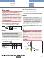
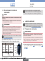
6.5 Typschild
Flow 1 2
2000 A 50,0 NBR RG
Made in Germany
00182076
W1X LU
G 2 P
med 16 bar
Pilot 1,6 - 10 bar
R
„R“ : VarianteTyp
Steuerdruck
Steuerfunktion
Identnummer
Durchflussrichtung Nennweite
Dichtungsmaterial
Gehäusematerial
Nenndruck
Anschlussart
6.6 Einsatzbedingungen
Antriebs-
größe [mm]
Antriebs-
werkstoff
Temperaturbereich
Medium (bei
PTFE-Dichtung)
Umgebung
1)
40 - 63 PA -10 ... siehe unten -10 ... siehe unten
80 - 125 PA -10 ... +180 °C -10 ... +60 °C
40 - 80 PPS -10 ... +180 °C +5 ... +140 °C
125 PPS -10 ... +180 °C +5 ... +90 °C
2)
1)
Mit Vorsteuerventil beträgt die max. Umgebungstemperatur + 55 °C.
2) Kurzzeitig bis maximal 140 °C.
Mediums-
temperatur [°C]
Umgebungs-
temperatur [°C]
100 120 140 160 180 200
70
60
50
40
30
20
∅ 63
∅ 50
∅ 40
6.6.1 Druckbereiche
Maximaler Steuerdruck Typ 2000:
Antriebs-
werkstoff
Antriebsgröße [mm]
Max. Steuerdruck
[bar]
PA 40 - 80 10
125 7
PPS 40 - 80 10
125 7
Mindeststeuerdrücke: Anströmung unter Sitz
(Mediumsstrom gegen Ventilschließrichtung)
Erforderlicher Mindeststeuerdruck P
min
bei Steuerfunktion A:
Antriebsgröße [mm] 40 50 63 80 100 125
P
min
[bar]
4,0 3,9 4,5 5,0 4,4 3,2
Der erforderliche Mindeststeuerdruck P
min
bei Steuerfunktion B und I
(Anströmung unter Sitz) ist abhängig vom Mediumsdruck
3)
.
Mindeststeuerdrücke: Anströmung über Sitz
(Mediumsstrom mit Ventilschließrichtung)
Der erforderliche Mindeststeuerdruck P
min
bei Steuerfunktion A
(Anströmung über Sitz) ist abhängig vom Mediumsdruck
3)
.
3) Die Druckdiagramme finden Sie in der Bedienungsanleitung im
Internet unter: www.buerkert.de
Typ 2000
deutsch

16
Montage
7 MONTAGE
GEFAHR!
Verletzungsgefahr durch hohen Druck in der Anlage.
▶ Vor dem Lösen von Leitungen oder Ventilen den Druck abschal-
ten und Leitungen entleeren.
Vorbereitende Arbeiten:
→ Durchflussrichtung beachten (siehe Typschild).
→ Rohrleitungen von Verunreinigungen säubern (Dichtungsmaterial,
Metallspäne etc.).
Geräte mit Schweißgehäuse:
Antrieb vom Ventilgehäuse demontieren:
→ Ventilgehäuse in eine Haltevorrichtung einspannen.
HINWEIS!
Beschädigung Sitzdichtung bzw. Sitzkontur!
→ Bei Steuerfunktion A und I Ventil öffnen: Unteren Steuerluftan-
schluss mit Druckluft (5 bar) beaufschlagen.
→ An der Schlüsselfläche des Nippels mit passendem Gabelschlüssel
ansetzen.
→ Antrieb vom Ventilgehäuse abschrauben.
Geräte mit Muffengehäuse:
→ Antrieb nur bei kundenspezifischem Erfordernis demontieren.
7.1 Einbau
WARNUNG!
Verletzungsgefahr bei unsachgemäßem Einbau!
Beschädigte Teile oder falsche Anziehdrehmomente können
Undichtheiten am Gerät verursachen.
▶ Zur Montage einen Gabelschlüssel verwenden.
▶ Anziehdrehmomente beachten (siehe Tabelle Drehmomente).
Geräte mit Zulassung nach DIN EN 161
Nach DIN EN 161 „Automatische Absperrventile für Gasbrenner und
Gasgeräte“ muss dem Ventil ein Schmutzfänger vorgeschaltet werden,
der das Eindringen eines 1-mm-Prüfdorns verhindert.
7.1.1 Gehäuse montieren
Schweißgehäuse:
→ Ventilgehäuse in Rohrleitungssystem einschweißen.
Andere Gehäuseausführungen:
→ Gehäuse mit Rohrleitung verbinden.
7.1.2 Antrieb montieren (Schweißgehäuse)
→ Graphitdichtung prüfen und bei Bedarf erneuern. Reste beim
Dichtungstausch vollständig entfernen.
WARNUNG!
Gefahr durch Schmierstoffe, die das Medium verunreinigen!
Bei Sauerstoffanwendungen besteht dadurch Explosionsgefahr!
▶ Bei spezifischen Anwendungen wie z. B. Sauerstoff- oder Analy-
seanwendungen nur zugelassene Schmierstoffe verwenden.
Typ 2000
deutsch

17
Montage
→ Nippelgewinde vor Wiedereinbau des Antriebs einfetten (z. B.
mit Klüberpaste UH1 96-402 der Firma Klüber).
Graphitdichtung
HINWEIS!
Beschädigung Sitzdichtung bzw. Sitzkontur!
→ Bei Steuerfunktion A und I Ventil öffnen: Unteren Steuerluftan-
schluss mit Druckluft (5 bar) beaufschlagen.
→ Antrieb in das Ventilgehäuse einschrauben, dabei Drehmomente
beachten (siehe Tabelle).
Nennweite (DN) 15 20 25 32-40 50-65
Drehmoment ± 3 [Nm]
45 50 60 65 70
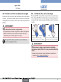
7.2 Drehen des Antriebs
Der Antrieb kann um 360 ° stufenlos gedreht werden.
→ Ventilgehäuse in eine Haltevorrichtung einspannen (wenn nötig).
HINWEIS!
Beschädigung Sitzdichtung bzw. Sitzkontur!
→ Bei Steuerfunktion A und I Ventil öffnen: Unteren Steuerluftan-
schluss mit Druckluft (5 bar) beaufschlagen.
→ An Schlüsselfläche des Nippels mit passendem Gabelschlüssel
gegenhalten.
→ Passenden Gabelschlüssel am Sechskant des Antriebs ansetzen.
WARNUNG!
Verletzungsgefahr durch Mediumsaustritt und Druckentladung!
Bei falscher Drehrichtung kann sich die Gehäuseschnittstelle lösen.
▶ Antrieb im Uhrzeigersinn (von oben gesehen) drehen.
Gabelschlüssel zum
Fixieren des Nippels
Gabelschlüssel
zum
Verdrehen des
Antriebs
7.3 Anschluss Steuermedium
GEFAHR!
Verletzungsgefahr durch hohen Druck in der Anlage!
▶ Vor dem Lösen von Leitungen oder Ventilen den Druck abschal-
ten und Leitungen entlüften.
WARNUNG!
Verletzungsgefahr durch ungeeignete Schläuche!
▶ Nur Schläuche verwenden, die für den angegebenen Druck- und
Temperaturbereich zugelassen sind.
▶ Datenblattangaben der Schlauchhersteller beachten.
Der Antrieb kann um 360 ° stufenlos gedreht werden. Siehe
Kapitel „7.2 Drehen des Antriebs“.
Typ 2000
deutsch

18
Inbetriebnahme
Steuerluftschlauch: Steuerluftschläuche der Größen 1/4“ bzw.
1/8“ (Antrieb ø 40 mm) verwenden.
Steuerfunktion Steuerluftanschluss
oben
unten
Steuerluft-
anschluss
oben unten
A
B
I
schließt öffnet
das Ventil
Aggressive Umgebung: freie Steuerluftanschlüsse über einen
Schlauch in neutrale Atmosphäre ableiten.
8 INBETRIEBNAHME
▶ Typschildangaben und die Hinweise zu Druck- und Tempe-
raturwerten in Kapitel „6 Technische Daten“ beachten.
8.1 Steuerdruck
WARNUNG!
Bei Steuerfunktion I - Gefahr bei Steuerdruckausfall!
Bei Druckausfall wird keine definierte Position erreicht.
▶ Für einen kontrollierten Wiederanlauf das Gerät zunächst mit
Steuerdruck beaufschlagen, danach erst das Medium aufschalten.
→ Steuerdruck entsprechend Typschildangaben (Kapitel „6“) und
Anströmung (Kapitel „8.2“ und „8.3“) einstellen.
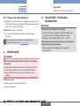
8.2 Anströmung über Sitz
Steuerfunktion A, SFA: schließt mit Federkraft mit dem Mediumsstrom. Der
Mediumsdruck unterstützt das Schließen und Abdichten des Ventilsitzes.
Das Öffnen des Ventils erfolgt durch den Steuerdruck.
WARNUNG!
Verletzungsgefahr durch Schließschlag!
Ein Schließschlag kann zum Bersten von Leitungen und Gerät führen.
▶ Ventile mit Anströmung über Sitz nur für gasförmige Medien und
Dampf einsetzen.
Um ein vollständiges Öffnen zu gewährleisten, muss der
Mindeststeuerdruck eingesetzt werden!
Typ 2000
deutsch

19
Inbetriebnahme
8.3 Anströmung unter Sitz
Steuerfunktion A, SFA: schließt mit Federkraft gegen Mediumsstrom.
Steuerfunktion B, SFB: schließt mit Steuerdruck gegen Mediumsstrom.
Der Mediumsdruck unterstützt das Öffnen des Ventils.
SFA/SFI
SFB/SFI
Anströmung unter Sitz
(gegen Medium schließend)
Anströmung über Sitz
(mit Medium schließend)
SFA
WARNUNG!
Sitzundichtheit bei zu geringem Mindeststeuerdruck (bei SFB
und SFI) oder zu hohem Mediumsdruck!
▶ Mindeststeuerdruck und Mediumsdruck beachten (siehe „6.6.1
Druckbereiche“.
8.4 Wartungsarbeiten
→ Sichtkontrolle einmal pro Jahr am Gerät durchführen. Je nach Ein-
satzbedingungen werden kürzere Wartungsintervalle empfohlen.
Verschleißteile: Dichtungen und Pendelteller.
→ Bei Undichtheiten das jeweilige Verschleißteil austauschen.
Die Wartungs- und Reparaturanleitung befindet sich im
Internet: www.buerkert.de
9 DEMONTAGE
GEFAHR!
Verletzungsgefahr durch Mediumsaustritt und Druckentladung!
Der Ausbau eines Geräts, das unter Druck steht, ist wegen plötzlicher
Druckentladung oder Mediumsaustritt gefährlich.
▶ Vor dem Ausbau den Druck abschalten und Leitungen entlüften.
Vorgehensweise:
→ Pneumatischen Anschluss lösen.
→ Gerät demontieren.
10 TRANSPORT, LAGERUNG,
ENTSORGUNG
HINWEIS!
Transportschäden und Lagerschäden!
▶ Gerät vor Nässe und Schmutz geschützt in einer stoßfesten
Verpackung transportieren und lagern.
▶ Zulässige Lagertemperatur: -20 … +65 °C.
Umweltschäden durch von Medien kontaminierte Geräteteile.
▶ Gerät und Verpackung umweltgerecht entsorgen!
Typ 2000
deutsch

20
Ce Quickstart
1
CE QUICKSTART .......................................................................................20
2 SYMBOLES
...................................................................................................20
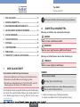
3 UTILISATION CONFORME ...................................................................21
4 CONSIGNES DE SÉCURITÉ FONDAMENTALES......................21
5 ADRESSES
...................................................................................................22
6 CARACTÉRISTIQUES TECHNIQUES .............................................22
7 MONTAGE
.....................................................................................................24
8 MISE EN SERVICE ....................................................................................26
9 DÉMONTAGE
............................................................................................... 28
10 TRANSPORT, STOCKAGE, ÉLIMINATION .................................... 28
Pour toute question, veuillez vous adresser à votre filiale de
distribution Bürkert.
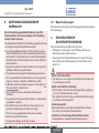
2 SYMBOLES
Mise en garde contre des blessures graves ou mortelles :
DANGER !
Met en garde contre un danger imminent.
AVERTISSEMENT !
Met en garde contre une situation éventuellement dangereuse.
Mise en garde contre des blessures moyennes ou légères :
ATTENTION !
Met en garde contre un risque éventuel.
REMARQUE !
Met en garde contre des dommages matériels.
Conseils et recommandations importants.
Renvoie à des informations dans ces instructions de service
ou dans d’autres documentations.
▶ identifie une consigne pour éviter un danger.
→ Identifie une opération que vous devez effectuer.
1 CE QUICKSTART
Ce quickstart contient des informations importantes.
▶ Lire attentivement ce quickstart et tenir compte des consignes de
sécurité.
▶ Ce quickstart doit être mis à disposition de chaque utilisateur.
▶ La responsabilité et la garantie légale concernant le type 2000 sont
exclues en cas de non-respect des instructions contenues dans ce
quickstart.
Ce quickstart explique à titre d'exemple le montage et la mise en
service de l'appareil. Vous trouverez la description détaillée de l'ap-
pareil dans les instructions de service du type 2000. Vous trouverez
le manuel utilisateur sur internet sous : www.buerkert.fr
Type 2000
français
La page est en cours de chargement...
La page est en cours de chargement...
La page est en cours de chargement...
La page est en cours de chargement...
La page est en cours de chargement...
La page est en cours de chargement...
La page est en cours de chargement...
La page est en cours de chargement...
La page est en cours de chargement...
La page est en cours de chargement...
La page est en cours de chargement...
-
 1
1
-
 2
2
-
 3
3
-
 4
4
-
 5
5
-
 6
6
-
 7
7
-
 8
8
-
 9
9
-
 10
10
-
 11
11
-
 12
12
-
 13
13
-
 14
14
-
 15
15
-
 16
16
-
 17
17
-
 18
18
-
 19
19
-
 20
20
-
 21
21
-
 22
22
-
 23
23
-
 24
24
-
 25
25
-
 26
26
-
 27
27
-
 28
28
-
 29
29
-
 30
30
-
 31
31


Burkert Type 2000 Guide de démarrage rapide
- Taper
- Guide de démarrage rapide
dans d''autres langues
- English: Burkert Type 2000 Quick start guide
- Deutsch: Burkert Type 2000 Schnellstartanleitung