
Quickstart
Type 8025 / 8035
Flowmeter
English

We reserve the right to make technical changes without notice.
Technische Änderungen vorbehalten.
Subject to technical changes.
© Bürkert SAS, 2013
Quickstart 1312/0_EU-ML 00565666 ORIGINAL_FR
1. ABOUT THE QUICKSTART.........................................................................3
2. INTENDED USE ................................................................................................4
3. BASIC SAFETY INFORMATION ...............................................................4
4. GENERAL INFORMATION ...........................................................................6
5. DESCRIPTION OF THE NAME PLATE ..................................................6
6. TECHNICAL DATA ...........................................................................................7
7. INSTALLATION ...............................................................................................13
8. WIRING ...............................................................................................................20
9. INSTALLATION AND COMMISSIONING ...........................................49
10. MAINTENANCE AND TROUBLESHOOTING ................................ 55
11. PACKAGING, TRANSPORT ...................................................................55
13. DISPOSAL OF THE PRODUCT ........................................................... 56

3
About the Quickstart
Type 8025/8035 /
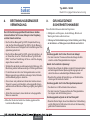
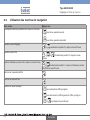
ATTENTION
Warns against a possible risk.
• Failure to observe this warning can result in substantial or minor
injuries.
NOTE
Warns against material damage.
• Failure to observe this warning may result in damage to the
device or system.
indicates additional information, advice or important
recommendations.
refers to information contained in this manual or in other
documents.
→ Indicates a procedure to be carried out.
1.2. Definition of the word "device"
The word "device" used within this manual always refers to the flow-
meter type 8025 or 8035.
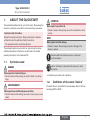
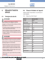
1. ABOUT THE QUICKSTART
The quickstart describes the life cycle of the device. Please keep this
manual in a safe place, accessible to all users and any new owners.
Important safety information.
Respect the safety instructions. Study in particular the chapters
entitled Intended Use and Basic Safety Instructions.
• The quickstart must be read and understood.
The quickstart explains how to install, set, and start-up the device.
A detailed description of the device can be found in the related
operating instructions on the delivered CD.
1.1. Symbols used
DANGER
Warns against an imminent danger.
• Failure to observe this warning can result in death or in serious
injury.
AVERTISSEMENT
Warns against a potentially dangerous situation.
• Failure to observe this warning can result in serious injury or even
death.
English

4
Intended use
Type 8025/8035 /
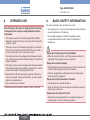
2. INTENDED USE
Use of the device that does not comply with the instructions
could present risks to people, nearby installations and the
environment.
• The compact version of the flowmeter type 8025 or 8035 is
designed to measure the flow rate of a liquid and to totalise the
volume of a liquid.
• The remote version of the flowmeter type 8025 is a transmitter
that must be connected to a 8020 or 8030 flow sensor with a
coil or a pulse output, only in "Low Power" version.
• This device must be protected against electromagnetic interfer-
ence, ultraviolet rays and, when installed outdoors, the effects of
climatic conditions.
• This device must be used in compliance with the characteristics
and commissioning and use conditions specified in the contrac-
tual documents and in the operating instructions.
• Requirements for the safe and proper operation of the device
are proper transport, storage and installation, as well as careful
operation and maintenance.
• Only use the device as intended.
→ Observe any existing restraints when the device is exported.
3. BASIC SAFETY INFORMATION
This safety information does not take into account:
• any contingencies or occurences that may arise during installation,
use and maintenance of the devices.
• the local safety regulations for which the operating company
is responsible including the staff in charge of installation and
maintenance.
Danger due to high pressure in the installation.
• Stop the circulation of fluid, cut off the pressure and drain the
pipe before loosening the process connections.
Danger due to electrical voltage.
• Shut down the electrical power source of all the conductors and
isolate it before carrying out work on the system.
• Observe all applicable accident protection and safety regula-
tions for electrical equipment.
Danger due to high temperatures of the fluid.
• Use safety gloves to handle the device.
• Stop the circulation of fluid and drain the pipe before loosening
the process connections.
Danger due to the nature of the fluid.
• Respect the prevailing regulations on accident prevention and
safety relating to the use of hazardous products.
English

5
Basic safety information
Type 8025/8035 /
Various dangerous situations
To avoid injury take care:
• not to use the device for the measurement of gas flow rates.
• not to use the device in explosive atmospheres.
• not to use the device in an environment incompatible with the
materials it is made of.
• not to subject the device to mechanical loads (e.g. by placing
objects on top of it or by using it as a step).
• not to make any external or internal modifications to the device.
• to prevent any unintentional power supply switch-on.
• to ensure that installation and maintenance work are
carried out by qualified, authorised personnel in possession of
the appropriate tools.
• to guarantee a defined or controlled restarting of the process,
after a power supply interruption.
• to use the device only if in perfect working order and in compli-
ance with the instructions provided in the operating instructions.
• to observe the general technical rules when installing and using
the device.
NOTE
The device may be damaged by the fluid in contact with.
• Systematically check the chemical compatibility of the compo-
nent materials of the device and the fluids likely to come into
contact with it (for example: alcohols, strong or concentrated
acids, aldehydes, alkaline compounds, esters, aliphatic com-
pounds, ketones, halogenated aromatics or hydrocarbons,
oxidants and chlorinated agents).
NOTE
Elements / Components sensitive to electrostatic discharges
• This device contains electronic components sensitive to electro-
static discharges. They may be damaged if they are touched by
an electrostatically charged person or object. In the worst case
scenario, these components are instantly destroyed or go out of
order as soon as they are activated.
• To minimise or even avoid all damage due to an electrostatic
discharge, take all the precautions described in the EN 61340-
5-1 and 5-2 norms.
• Also ensure that you do not touch any of the live electrical
components.
English

6
General information
Type 8025/8035 /
4. GENERAL INFORMATION
4.1. Manufacturer's address and
international contacts
To contact the manufacturer of the device, use following address:
Bürkert SAS
Rue du Giessen
BP 21
F-67220 TRIEMBACH-AU-VAL
You may also contact your local Bürkert sales office.
The addresses of our international sales offices are available on the
internet at: www.burkert.com
4.2. Warranty conditions
The condition governing the legal warranty is the conforming use of
the device type 8025/8035 in observance of the operating condi-
tions specified in this manual.
4.3. Information on the Internet
You can find the operating instructions and technical data sheets
regarding the type 8025 or the type 8035 or at: www.burkert.com.
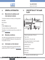
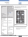
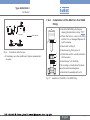
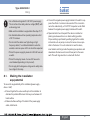
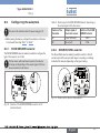
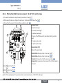
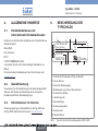
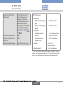
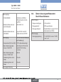
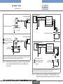
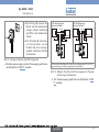
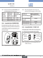
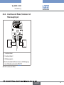
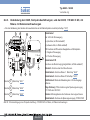
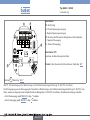
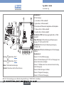
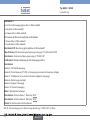
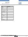
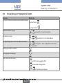
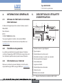
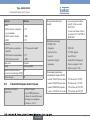
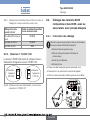
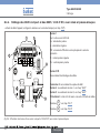
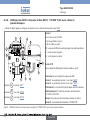
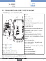
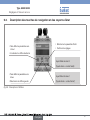
5. DESCRIPTION OF THE NAME
PLATE
FLOW SE35/8035 HALL SUPPLY: 12-36V ... 70 mA
Output: 1x4-20mA IP65
2xRel: 30V and 42V peak or 60V ... max.
S/N 11 026
00552726
W44MG
Made in France
12
67910
4
8
3
5
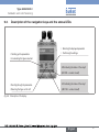
1. Measured quantity and type of the device
2. Type of sensor
3. Characteristics of the current output
4. Power supply and maximum of current consumption
5. Protection class of the device
6. Manufacturing code
7. Conformity logo
8. Specification of the relay outputs
9. Serial number
10. Order code
Fig. 1: Name plate of the 8025 / 8035 flowmeter
English

7
Technical data
Type 8025/8035 /
6. TECHNICAL DATA
The following technical data are relevant for a 8025 compact or a
8035 and for the remote 8025 connected to a Bürkert flow sensor
8020 / 8030 in a "Low Power" version only.
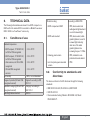
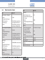
6.1. Conditions of use
Ambient temperature
• 8025 compact, 115/230 V AC,
not UR or CSA recognized
• 8035 compact, 115/230 V AC,
not UR or CSA recognized
• other versions, not UR or CSA
recognized
• UR and CSA recognized
versions
• -10 to 50 °C
• -10 to 50 °C
• -10 to 60 °C
• -10 to 40 °C
Air humidity < 80%, non condensated
Degree of pollution (UR and CSA
recognized versions)
Degree 2 according to EN
61010-1
Installation category (UR and CSA
recognized versions)
Category I according to
UL61010-1
Max. height above sea level 2000 m
Protection rating
• 8025 compact and 8035
• 8025 wall-mounted
• Housing, panel version
• non front parts, panel-mounted
version
According to EN 60529
• IP65, device wired and
cable glands tightened and
cover lid screwed tight.
• IP65, device wired, cable
glands tightened, cover lid
screwed tight and entry
item nuts of the cable
glands tightened at a
screwing torque of 1.5 Nm.
• IP65, installation com-
pleted and closed cabinet
• IP20
6.2. Conformity to standards and
directives
The device conforms to the EC directives through the following
standards:
• EMC: EN 61000-6-2, EN 61000-6-3, EN 550022
• LVD: EN 61010-1
• Environnemental testing: Vibration: EN 60068-2-6, Shock:
EN 60068-2-27.
English

8
Technical data
Type 8025/8035 /
Pressure: article 3§3 of the Pressure Directive 97/23/CE. Acc. to
the Pressure Directive 97/23/CE: the device can only be used in the
following cases (depending on the max. pressure, the DN of the pipe
and the fluid):
Type of fluid Conditions
8025 8035
1)
Fluid group 1, par.
1.3.a
DN25 only DN ≤ 25 only
Fluid group 2 par. 1.3.a
DN ≤ 32
or DN > 32 and
PNxDN ≤ 1000
DN ≤ 32
or DN > 32 and
PNxDN ≤ 1000
Fluid group 1 par. 1.3.b
DN ≤ 25
or DN > 25 and
PNxDN ≤ 2000
PNxDN ≤ 2000
Fluid group 2 par. 1.3.b DN ≤ 400 DN ≤ 200
1)
For the type 8035: S030 sensor-fitting, DN6 to DN65, in PP, PVC,
PVDF, brass or stainless steel.
The UL recognized devices with variable key PU01 comply with the fol-
lowing standards:
• UL 61010-1
• CAN/CSA-C22.2 n° 61010-1
6.3. General data
Pipe diameter
• 8025 flowmeter
• 8025 transmitter (remote
versions)
• 8035 flowmeter
• DN20 (except for the DN
specified p.15) to DN400
• DN06 to DN400
• DN06 to DN65
Type of fitting • S020, for a compact 8025
• S030, for a 8035
Type of fluid • liquid
• viscosity: max. 300 cSt
• rate of solid particles: max.
1%
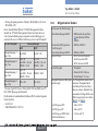
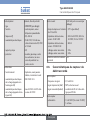
Fluid temperature (compact ver-
sions)
• with fitting in PVC
• with fitting in PP
• with fitting in PVDF, stainless
steel or brass
The fluid temperature may be
restricted by the fluid pressure,
the material the flow sensor is
made of and the material the
S020 or S030 fitting used is
made of. See "Fig. 2" and "Fig.
3".
• 0 to +50 °C
• 0 to +80 °C
• -15 to +80 °C
English

9
Technical data
Type 8025/8035 /
Fluid pressure (compact ver-
sions)
• 8025 compact
• 8035 with S030 fitting in
plastic
• 8035 with S030 fitting in metal
The fluid pressure may be
restricted by the fluid tem-
perature, the material the flow
sensor is made of (only for the
compact 8025) and the material
the fitting used is made of. See
"Fig. 2" and "Fig. 3".
• PN10
• PN10
• PN16 (PN40 on request)
Flow rate measurement
• Measurement range
- Sensor with pulse output
(Hall)
- Sensor with a sinus output
(coil)
• Accuracy
- with a teach-in procedure
- with the K factor of the
fitting used
• Linearity
1)
• Repeatability
1)
- 0.3 m/s to 10 m/s
- 0.5 m/s to 10 m/s
- 1 % of the measured value
(at the value of the teach-in
flow rate)
- 2,5 % of the measured
value
• ±0,5 % of the full scale
• ±0,4 % of the measured value
1)
Determined in the following reference conditions: medium = water, water
and ambient temperatures 20 °C, min. upstream and downstream distances
respected, appropriate pipe dimensions
10
9
8
7
6
5
4
3
2
1
0
-15 0 +20 +40 +60
PVDF
PVDF (PN10)
PVC (PN10)
PP (PN10)
PVC + PP
11
P (bar)
T (°C)
+80
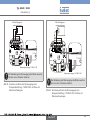
A
Metal
A: range of use
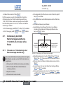
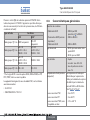
Fig. 2: Fluid temperature /pressure dependency curves for the
8025 compact version, depending on the material the
S020 fitting is made of
English

10
Technical data
Type 8025/8035 /
10
9
8
7
6
5
4
3
2
1
0
-30
-10 +10 +30 +50 +70 +90 +110
PVDF (PN10)
PVC (PN10)
PP (PN10)
PVC + PP
PVDF
16
15
14
13
12
11
A
P (bar)
T °C
A
Metal
A: range of use
Fig. 3: Fluid temperature /pressure dependency curves for the
8035 compact version, depending on the material the
S030 fitting is made of
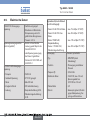
6.4. Mechanical data
Part Material
Sensor holder - Paddle-wheel
• 8025, compact versions
• 8025, remote versions
• 8035
• PVDF
• Refer to the operating instruc-
tions of the remote sensor
• Refer to the operating instruc-
tions of the S030 sensor-fitting
Axis and bearings of the
paddle-wheel
• 8025, compact versions
• 8025, remote versions
• 8035
• Ceramics
• Refer to the operating instruc-
tions of the remote sensor
• Refer to the operating instruc-
tions of the S030 sensor-fitting
Seals
• 8025, compact versions
• 8025, remote versions
• FKM (EPDM delivered with the
device)
• Refer to the operating instruc-
tions of the remote sensor
Nut
• 8025, compact versions • PC
English

11
Technical data
Type 8025/8035 /
Part Material
Housing
• 8025, compact or remote
versions
• 8025, wall-mounted versions
• 8035
• PC
• ABS
• PC
Cover
• 8025 compact versions or
8035
• 8025 panel versions
• 8025, wall-mounted versions
• PC (Cover with lid)
• PC
• ABS
Front foil Polyester
Screws (4) Stainless steel
Male fixed connector and
female connector (type 2508)
PA
Cable glands PA
6.5. Electrical data
Power supply 12-36 V DC • filtered and regulated
• SELV circuit (safety extra low
voltage), with a safe energy
level
• oscillation rate: ±10 %
Power supply (not supplied) • limited power source
according to § 9.3 of
EN 61010-1 standard
• or class 2 source according
to UL 1310/1585 and
EN 60950-1 standards
Power supply 115/230 V AC
• frequency
• supplied voltage
• current
• integrated protection
• power
• 50/60 Hz
• 27 V DC, regulated
• max. 250 mA
• 250 mA time-delay fuse
• Compact version: 6 VA
• Wall-mounted version 3 VA
Current consumption (without the
consumption of the 4-20 mA output)
• 12-36 V DC version with relays
• 12-36 V DC version without
relays
• 115/230 V AC compact version
• 115/230 V AC wall-mounted
version
• 70 mA max. (at 12 V DC)
• 25 mA max. (at 12 V DC)
• 125 mA max. (at 27 V DC)
• 250 mA max. (at 27 V DC)
English

12
Technical data
Type 8025/8035 /
Pulse output
• type
• function
• frequency (f)
• electrical data
• duty cycle
• protection
polarized, potential-free
• NPN/PNP (wiring dependant)
• pulse output, adjustable pulse
value
• 2,5-400 Hz
• 5-36 V DC, 100 mA max.,
voltage drop 2,5 V DC at
100 mA
• 0,5
• galvanically isolated, and
protected against over-
voltages, polarity reversals
and short-circuits
Relay outputs
• operating
• electrical data of the load (non
UL recognized devices)
• electrical data of the load (UL
recognized devices)
• hysteresis, adjustable
thresholds, normally open
• 230 V AC / 3 A
• 30 V AC max. and 42 V peak
or 60 V DC max.
Current output
• response time (10% to 90%)
• max. loop impedance,
12-36 V DC version
• max. loop impedance,
115/230 V AC version
• wiring, version without relays
• wiring, version with relays
4-20 mA, sinking or sourcing
mode (through wiring)
• 5,75 s (default)
• 900W at 30 V DC, 600W at
24 V DC, 50 W at 12 V DC
• 800 W
• 2-wire
• 3-wire
Protection against polarity
reversals
yes
6.6. Specifications of the connected
flow sensor
Sensor input
• signal frequency
• pulse signal (Hall)
• sinus signal (coil)
• 2,5 to 400 Hz
• NPN, open collector
• typical sensitivity of 35 mV peak-
peak, at 252 Hz
Sensor output
• power supply • 10-34 V DC (V+ subtract 2
V DC), 1 mA max.
English

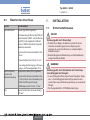
13
Installation
Type 8025/8035 /
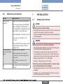
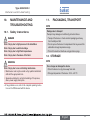
7. INSTALLATION
7.1. Safety instructions
DANGER
Risk of injury due to electrical voltage.
• Shut down the electrical power source of all the conductors and
isolate it before carrying out work on the system.
• Observe all applicable accident protection and safety regulations for
electrical equipment.
WARNING
Risk of injury due to non-conforming installation.
• The electrical and fluid installation can only be carried out by quali-
fied and skilled staff with the appropriate tools.
• Install appropriate safety devices (correctly rated fuse and/
or circuit-breaker); for the versions with 115/230 V AC power
supply, insert a protection device between phase and neutral.
• Respect standard NF C 15-100 / IEC 60364.
• Observe mounting instructions of the fitting.
Risk of injury due to unintentional switch on of power supply
or uncontrolled restarting of the installation.
• Take appropriate measures to avoid unintentional activation of the
installation.
• Guarantee a set or controlled restarting of the process subse-
quent to any intervention on the device.
6.7. Electrical connection
Version Wiring features
With male fixed
connector
Female connector (type 2508 supplied)
For the female connector type 2508 with
order code 438811 and the female con-
nector type 2509 (not supplied) with order
code 162673, use a shielded cable.
• external diameter of the cable: 5 to 8 mm
• cross section of the wires: 0.2 to
1.5 mm
2
• max. length of the power supply, current
output and pulse output connection
cables: 50 m
With terminal strip,
with or without cable
glands
Shielded cable (not supplied):
• external diameter of the cable: 6 to
12 mm (4 to 6 mm when using a mul-
tiway seal)
• cross section of the wires: 0.2 to
1.5 mm
2
All Cross section of the local earthing wire:
0.75 mm
2
English

14
Installation
Type 8025/8035 /
WARNING
Risk of injury if the fluid pressure/ temperature dependency
is not respected.
• Take account of fluid temperature-pressure dependancy
according to the nature of the materials the fitting is made of
(see the technical data and the operating instructions of the
fitting used).
• Comply with the Pressure Directive 97/23/EC.
Protect this device against electromagnetic inter-
ference, ultraviolet rays and, when installed outdoors,
the effects of the climatic conditions.
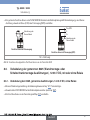
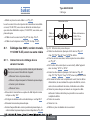
7.2. Installation of a compact version
7.2.1. Instructions for installing a compact
version onto the pipe
The 8025 flowmeter has to be inserted into an S020 fitting mounted
on a pipe.
The 8035 flowmeter has to be installed on the pipe using the S030
sensor-fitting.
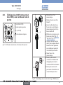
→ Choose an S020 or S030 fitting appropriate to the velocity of
the fluid inside the pipe: refer to the graphs below:
English

15
Installation
Type 8025/8035 /
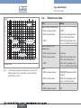
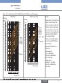
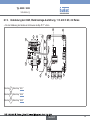
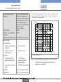
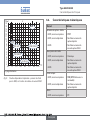
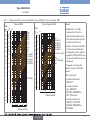
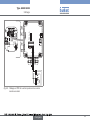
Table 1: Flow rate/ fluid velocity/ DN of S020 fitting and of S030 sensor-fitting diagram
S020 fitting
0.10.3 0.51 35 10
0.01
0.02
0.05
0.1
0.2
0.5
1
2
5
10
20
50
100
200
m
3
/h
0.2
0.5
1
2
5
10
20
50
100
200
500
1000
2000
3000
l/min
0.3
0.51 35 10
30
m/s
fps
US gpm
0.05
0.1
0.2
0.5
1
2
5
10
20
50
100
200
500
1000
DN 65
DN 50 (DN65)*
DN 40 (DN50)*
DN 32 (DN40)*
DN 25 (DN32)*
DN 20 (DN25)*
500
1000
2000
2000
5000
10000
5000
20000
5000
10000
20000
30000
50000
100000
DN 400
DN 350
DN 300
DN 250
DN 200
DN 150
DN 125
DN 100
DN 80
Flow rate
Flow velocity
Example
1)
S030 sensor-fitting
0.10.3 0.51 35 10
0.01
0.02
0.05
0.1
0.2
0.5
1
2
5
10
20
50
100
200
m
3
/h
l/min
0.30.5 13510
30
m/s
fps
gpm
0.05
0.1
0.2
0.5
1
2
5
10
20
50
100
200
500
1000
DN65
DN50 (DN65)*
DN40 (DN50)*
DN32 (DN40)*
DN25 (DN32)*
DN20 (DN25)*
DN15 (DN15 / DN20)*
DN08
DN06
0.2
0.5
1
2
5
10
20
50
100
200
500
1000
2000
3000
Example
Flow rate
Flow velocity
Example:
• Specification: if the nominal flow
rate is 10 m
3
/h, the ideal flow
velocity is between 2 and 3 m/s.
• Solution: intersection between
flow rate and flow velocity in the
graph gives the appropriate pipe
diameter, DN40 (or DN50 for
the asterisked fittings).
1)
The device cannot be installed
onto the following DN20 fittings:
* For the fittings:
• with external threads acc. to
SMS 1145.
• with weld ends
acc. to SMS 3008,
BS 4825 / ASME BPE or
DIN 11850 Rg2.
• Clamp acc. to
SMS 3017 / ISO 2852,
BS 4825 / ASME BPE or
DIN 32676.
English

16
Installation
Type 8025/8035 /
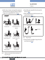
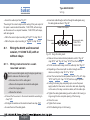
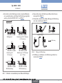
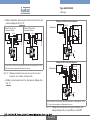
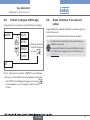
→ Install the device on the pipe in such a way that the upstream and
downstream distances are respected according to the design of
the pipes, refer to standard EN ISO 5167-1 and "Fig. 4":
flow direction
50 x DN 5 x DN
40 x DN 5 x DN
25 x DN 5 x DN 20 x DN 5 x DN
18 x DN 5 x DN 15 x DN 5 x DN
With control valve Pipe with 2 elbows at 90° in 3
dimensions
Pipe with 2 elbows at 90° Pipe with 1 elbow at 90° or 1
T-piece
With pipe expansion With pipe reduction
Fig. 4: Upstream and downstream distances depending on the
design of the pipes
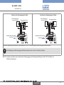
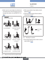
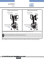
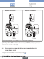
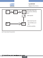
→ Ensure that the pipe is always filled in the section around the
device (see "Fig. 5").
→ When mounting vertically ensure that the flow direction is in an
upward direction (see "Fig. 5").
Horizontal mounting
Correct Incorrect
Vertical mounting
Correct Incorrect
flow direction
Fig. 5: Filling of the pipe
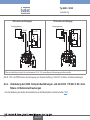
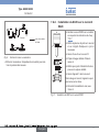
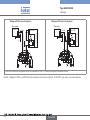
→ Prevent the formation of air bubbles in the pipe in the section
around the device (see "Fig. 6").
English

17
Installation
Type 8025/8035 /
Correct
flow direction
Incorrect
Correct Incorrect
Fig. 6: Air bubbles within the pipe
→ If necessary, use a flow conditioner to improve measurement
accuracy.
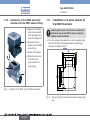
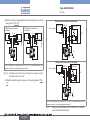
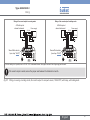
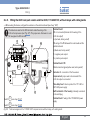
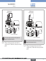
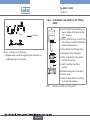
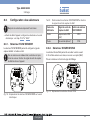
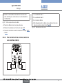
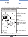
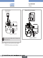
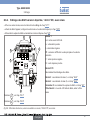
7.2.2. Installation of the 8025 on the S020
fitting
2
1
3
4
5
6
→ Install the S020 fitting into the pipe
obeying the instructions in chap. "7.2.1"
→ Check that there is a seal on the fitting
and that it is not damaged. Replace the
seal if necessary.
→ Insert nut 3 on fitting 5.
→ Insert snap ring 2 into groove 4.
→ Check that seal 6 is correctly inserted on
the flow sensor.
→ Insert device 1 into the fitting.
If the mounting is correctly done the device
cannot be turned around anymore.
→ Hand lock the assembly with nut 3.
Fig. 7: Installation of the 8025 on the S020 fitting
English

18
Installation
Type 8025/8035 /
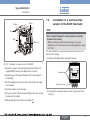
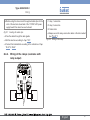
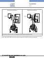
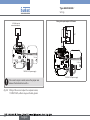
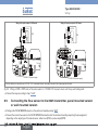
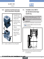
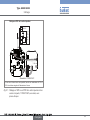
7.2.3. Installation of the SE35 electronic
module onto the S030 sensor-fitting
1
2
3
→ Respect the installation
instructions contained
in the operating instruc-
tions of the fitting used.
→ Insert the electronic
module 2 into the S030
sensor-fitting.
→ Fix with a 30° rotation.
→ Tighten the side screw
3 to lock the elec-
tronic module to the
sensor-fitting.
Fig. 8: Installation of the SE35 onto the S030 sensor-fitting
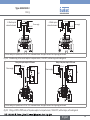
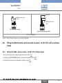
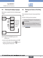
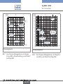
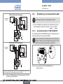
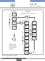
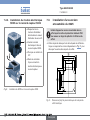
7.3. Installation of a panel version of
the 8025 flowmeter
Install the panel version of the device in a cabinet with
a protection class at least IP54 to ensure a degree of
pollution 2 inside the cabinet.
→ To cut the opening in the cabinet door, use the supplied cutting
plan of the frontage of the electrical cabinet, respecting the
dimensions indicated in "Fig. 9".
95
80
76
50
95
80
76
50
Fig. 9: Dimensions [mm] of the electrical cabinet frontage cutting
plan
English

19
Installation
Type 8025/8035 /
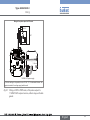
Seal
Nut
Washer
Screw
Cable clip
Fig. 10: Installation of a panel version of the 8025
→ Insert the 4 screws in the housing (from the front). Use the 4
supplied M4*25 screws if the cabinet door is too thick.
→ Insert the seal on the external threads of the 4 screws (rear of
the housing).
→ Put the assembly on the cutout, electronics turned to the inside
of the cabinet.
→ Put the 4 washers on the 4 screws.
→ Put a nut on each of the 4 screws and tighten the nuts to secure
the device to the cabinet.
→ Wire according to the instructions in chapter "8".
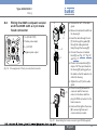
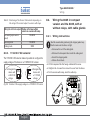
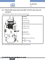
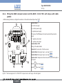
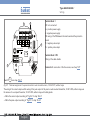
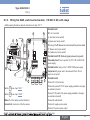
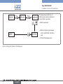
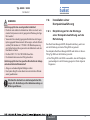
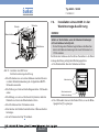
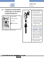
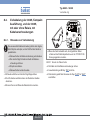
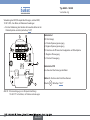
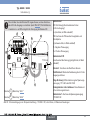
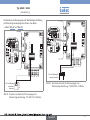
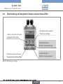
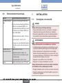
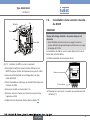
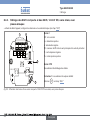
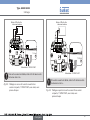
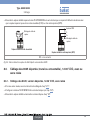
7.4. Installation of a wall-mounted
version of the 8025 flowmeter
NOTE
Risk of material damage if the cable glands are not tightly
screwed on the housing
• Before installing the wall-mounted housing on its support,
tighten the nuts of the entry item of the cables glands at a torque
of 1.5 Nm.
The flow transmitter in a wall-mounted version has 4 holes in the
bottom of the housing.
→ Remove the blanking strips covering the screws.
Blanking strips
ENTER
0....9
FLOW
Nut of the entry item
→ Loosen the 4 screws and open the cover to get access to the
holes [1].
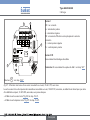
English

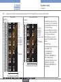
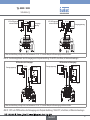
20
Wiring
Type 8025/8035 /
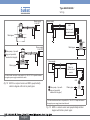
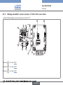
1
1
1
1
230V
LN
230V
T 250 mA
56789 10
LN
230V
NPN SENSOR
1 PULSE INPUT
2 -
3 +
4 NC
SUPPLY
1234PE
3A/230VAC
REL1
REL2
FLOW SENSOR
FLOW SENSOR
COILNPN
CURRENT
SOURCE SINK
COIL SENSOR
1
2
3 NC
4 NC
L+
L-
PE
P-
P+
NC
L+
L-
PE
P-
P+
Iout
PULSE
OUTPUT
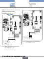
Without
With
Relays
Supply
12..36Vdc
106 mm
106 mm
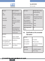
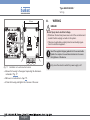
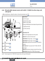
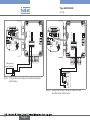
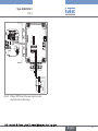
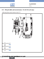
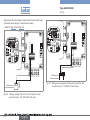
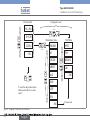
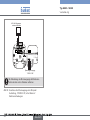
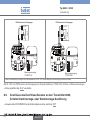
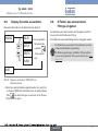
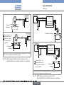
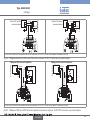
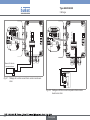
Fig. 11: Installation of a wall-mounted version
→ Secure the housing to the support respecting the dimensions
indicated in "Fig. 11".
→ Wire acc. to instructions in chap. "8".
→ Close the housing and tighten the 4 screws of the cover.
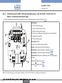
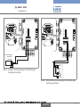
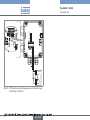
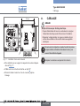
8. WIRING
DANGER
Risk of injury due to electrical voltage.
• Shut down the electrical power source of all the conductors and
isolate it before carrying out work on the system.
• Observe all applicable accident protection and safety regula-
tions for electrical equipment.
Insert the supplied stopper gaskets into the unused cable
glands of a compact or a wall-mounted version to ensure
the tightness of the device.
Only move the selectors when the power supply is off.
English
La page est en cours de chargement...
La page est en cours de chargement...
La page est en cours de chargement...
La page est en cours de chargement...
La page est en cours de chargement...
La page est en cours de chargement...
La page est en cours de chargement...
La page est en cours de chargement...
La page est en cours de chargement...
La page est en cours de chargement...
La page est en cours de chargement...
La page est en cours de chargement...
La page est en cours de chargement...
La page est en cours de chargement...
La page est en cours de chargement...
La page est en cours de chargement...
La page est en cours de chargement...
La page est en cours de chargement...
La page est en cours de chargement...
La page est en cours de chargement...
La page est en cours de chargement...
La page est en cours de chargement...
La page est en cours de chargement...
La page est en cours de chargement...
La page est en cours de chargement...
La page est en cours de chargement...
La page est en cours de chargement...
La page est en cours de chargement...
La page est en cours de chargement...
La page est en cours de chargement...
La page est en cours de chargement...
La page est en cours de chargement...
La page est en cours de chargement...
La page est en cours de chargement...
La page est en cours de chargement...
La page est en cours de chargement...
La page est en cours de chargement...
La page est en cours de chargement...
La page est en cours de chargement...
La page est en cours de chargement...
La page est en cours de chargement...
La page est en cours de chargement...
La page est en cours de chargement...
La page est en cours de chargement...
La page est en cours de chargement...
La page est en cours de chargement...
La page est en cours de chargement...
La page est en cours de chargement...
La page est en cours de chargement...
La page est en cours de chargement...
La page est en cours de chargement...
La page est en cours de chargement...
La page est en cours de chargement...
La page est en cours de chargement...
La page est en cours de chargement...
La page est en cours de chargement...
La page est en cours de chargement...
La page est en cours de chargement...
La page est en cours de chargement...
La page est en cours de chargement...
La page est en cours de chargement...
La page est en cours de chargement...
La page est en cours de chargement...
La page est en cours de chargement...
La page est en cours de chargement...
La page est en cours de chargement...
La page est en cours de chargement...
La page est en cours de chargement...
La page est en cours de chargement...
La page est en cours de chargement...
La page est en cours de chargement...
La page est en cours de chargement...
La page est en cours de chargement...
La page est en cours de chargement...
La page est en cours de chargement...
La page est en cours de chargement...
La page est en cours de chargement...
La page est en cours de chargement...
La page est en cours de chargement...
La page est en cours de chargement...
La page est en cours de chargement...
La page est en cours de chargement...
La page est en cours de chargement...
La page est en cours de chargement...
La page est en cours de chargement...
La page est en cours de chargement...
La page est en cours de chargement...
La page est en cours de chargement...
La page est en cours de chargement...
La page est en cours de chargement...
La page est en cours de chargement...
La page est en cours de chargement...
La page est en cours de chargement...
La page est en cours de chargement...
La page est en cours de chargement...
La page est en cours de chargement...
La page est en cours de chargement...
La page est en cours de chargement...
La page est en cours de chargement...
La page est en cours de chargement...
La page est en cours de chargement...
La page est en cours de chargement...
La page est en cours de chargement...
La page est en cours de chargement...
La page est en cours de chargement...
La page est en cours de chargement...
La page est en cours de chargement...
La page est en cours de chargement...
La page est en cours de chargement...
La page est en cours de chargement...
La page est en cours de chargement...
La page est en cours de chargement...
La page est en cours de chargement...
La page est en cours de chargement...
La page est en cours de chargement...
La page est en cours de chargement...
La page est en cours de chargement...
La page est en cours de chargement...
La page est en cours de chargement...
La page est en cours de chargement...
La page est en cours de chargement...
La page est en cours de chargement...
La page est en cours de chargement...
La page est en cours de chargement...
La page est en cours de chargement...
La page est en cours de chargement...
La page est en cours de chargement...
La page est en cours de chargement...
La page est en cours de chargement...
La page est en cours de chargement...
La page est en cours de chargement...
La page est en cours de chargement...
La page est en cours de chargement...
La page est en cours de chargement...
La page est en cours de chargement...
La page est en cours de chargement...
La page est en cours de chargement...
La page est en cours de chargement...
La page est en cours de chargement...
La page est en cours de chargement...
La page est en cours de chargement...
La page est en cours de chargement...
La page est en cours de chargement...
La page est en cours de chargement...
La page est en cours de chargement...
La page est en cours de chargement...
La page est en cours de chargement...
La page est en cours de chargement...
La page est en cours de chargement...
La page est en cours de chargement...
La page est en cours de chargement...
La page est en cours de chargement...
La page est en cours de chargement...
La page est en cours de chargement...
-
 1
1
-
 2
2
-
 3
3
-
 4
4
-
 5
5
-
 6
6
-
 7
7
-
 8
8
-
 9
9
-
 10
10
-
 11
11
-
 12
12
-
 13
13
-
 14
14
-
 15
15
-
 16
16
-
 17
17
-
 18
18
-
 19
19
-
 20
20
-
 21
21
-
 22
22
-
 23
23
-
 24
24
-
 25
25
-
 26
26
-
 27
27
-
 28
28
-
 29
29
-
 30
30
-
 31
31
-
 32
32
-
 33
33
-
 34
34
-
 35
35
-
 36
36
-
 37
37
-
 38
38
-
 39
39
-
 40
40
-
 41
41
-
 42
42
-
 43
43
-
 44
44
-
 45
45
-
 46
46
-
 47
47
-
 48
48
-
 49
49
-
 50
50
-
 51
51
-
 52
52
-
 53
53
-
 54
54
-
 55
55
-
 56
56
-
 57
57
-
 58
58
-
 59
59
-
 60
60
-
 61
61
-
 62
62
-
 63
63
-
 64
64
-
 65
65
-
 66
66
-
 67
67
-
 68
68
-
 69
69
-
 70
70
-
 71
71
-
 72
72
-
 73
73
-
 74
74
-
 75
75
-
 76
76
-
 77
77
-
 78
78
-
 79
79
-
 80
80
-
 81
81
-
 82
82
-
 83
83
-
 84
84
-
 85
85
-
 86
86
-
 87
87
-
 88
88
-
 89
89
-
 90
90
-
 91
91
-
 92
92
-
 93
93
-
 94
94
-
 95
95
-
 96
96
-
 97
97
-
 98
98
-
 99
99
-
 100
100
-
 101
101
-
 102
102
-
 103
103
-
 104
104
-
 105
105
-
 106
106
-
 107
107
-
 108
108
-
 109
109
-
 110
110
-
 111
111
-
 112
112
-
 113
113
-
 114
114
-
 115
115
-
 116
116
-
 117
117
-
 118
118
-
 119
119
-
 120
120
-
 121
121
-
 122
122
-
 123
123
-
 124
124
-
 125
125
-
 126
126
-
 127
127
-
 128
128
-
 129
129
-
 130
130
-
 131
131
-
 132
132
-
 133
133
-
 134
134
-
 135
135
-
 136
136
-
 137
137
-
 138
138
-
 139
139
-
 140
140
-
 141
141
-
 142
142
-
 143
143
-
 144
144
-
 145
145
-
 146
146
-
 147
147
-
 148
148
-
 149
149
-
 150
150
-
 151
151
-
 152
152
-
 153
153
-
 154
154
-
 155
155
-
 156
156
-
 157
157
-
 158
158
-
 159
159
-
 160
160
-
 161
161
-
 162
162
-
 163
163
-
 164
164
-
 165
165
-
 166
166
-
 167
167
-
 168
168
-
 169
169
-
 170
170
-
 171
171
-
 172
172
-
 173
173
-
 174
174


Burkert 8035 Guide de démarrage rapide
- Taper
- Guide de démarrage rapide
- Ce manuel convient également à
dans d''autres langues
- English: Burkert 8035 Quick start guide
- Deutsch: Burkert 8035 Schnellstartanleitung
Documents connexes
Autres documents
-
Sony RM-EZ4T Le manuel du propriétaire
-
Traxxas TRX-4 Bronco Mode d'emploi
-
-
JVC nx pn10 Le manuel du propriétaire
-
Posiflex KS-6715 Manuel utilisateur
-
 Palram 702563 Guide d'installation
-
-
GE 20622 Manuel utilisateur
-
GF MULTI/JOINT® 3000 Plus DN50-DN400 Le manuel du propriétaire
-
salmson Nexis Advens Mode d'emploi
