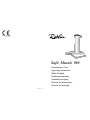
Robin Safir Murale 900 Operating Instructions Manual
- Catégorie
- Hottes
- Taper
- Operating Instructions Manual

4 3 2 9 0 6 6
Dir . 8 9 / 3 3 6 / CEE
7 3 / 2 3 / C EE
Istruzioni per l'uso
Operating instructions
Mode d'emploi
Bedienungsanleitung
Gebruiksaanwijzing
Manual de instrucciones
Manual de instruções
Safir Murale 900

Part 1ª - INSTALLATION INSTRUCTIONS
1 - GENERAL INFORMATION
This canopy hood is designed to be fixed to any rigid vertical surface, above a gas or electric
hotplate, and can be used either in the extraction mode (ducted to the outside) or in the
recirculation mode (internal recycling).
Before commencing the installation, consideration should be given to the difficulties
to be found during the installation and to the bulky weight of the hood.
The installation work must be undertaken by a qualified and competent person.
The manufacturer disclaims all liability for any damage or injury caused as a result of
not following the instructions for installation contained in the following text.
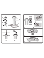
2 - COMPONENTS
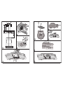
The cooker hood is made up of the following components (fig. 1):
2.1- No. 1 canopy item C, including controls and worktop illumination
2.2- No. 1 telescopic chimney stack A complete with extractor group
2.3- No. 1 flange 120 or 150 F
2.4- No. 1 venting grilles G
2.5- No. 1 spigot R
2.6- No. 1 bag containing:
No. 1 wall bracket S to fix the hood, screws, plugs and documents
3 - SAFETY WARNINGS
3.1- When used in the extraction mode the cooker hood ducting must not be connected
to a flue which is used for exhausting fumes from appliances supplied with energy
other than electric such as a central heating flue or water heating flue.
3.2- Before connecting to the mains supply ensure that the mains voltage corresponds
with the voltage on the rating plate inside the cooker hood.
3.3- Connect the cooker hood to the mains via a double pole switch which has 3 mm
clearance between the contacts.
3.4- This appliance must be earthed.
3.5- When installed, the hood must be positioned at least 65 cm above a cooking appli-
ance.
3.6- Never do flambé cooking under this cooker hood.
3.7- Never leave frying pans unattended during use as overheated fats and oils may catch
fire.
3.8- Before carrying out any kind of cleaning or maintenance, disconnect the hood from
the mains supply.
3.9- If the room where the hood is to be used contains a fuel burning appliance such as
a central heating boiler then this must be of the room sealed or balanced flue type.
If other types of flue or appliance are fitted ensure that there is an adequate supply
of air into the room. When the cooker hood is used in conjunction with appliances
supplied with energy other than electricity, the negative pressure in the room must not
exceed 0,04 mbar to prevent fumes been drawn back into the room by the cooker
hood.
4 - INSTALLATION
The versatility of the extractor group in this hood allows it to be installed in one of follow
different ways:
1 - Air outlet turned upwards (extraction or recirculation mode).
2 - Air outlet turned towards the wall (extraction mode only).
3 - Air outlet turned to the right or left (extraction mode only).
In this case the air must be ducted to the outside.
To install the hood properly, follow the procedures indicated below:
4.1- Selecting the type of fitting
4.2- Fixing the chimney A to the hood canopy C
4.3- Fixing the hood to the wall
4.4- Ducting or recirculation fitting
4.5- Electrical connection and working test
4.1- Selecting the type of fitting
1 - Air outlet turned upwards (fig. 2a-b)
In this case the hood can be used either in extraction mode (fig. 2a) or in recirculation mode
(fig. 2b).
2 - Air outlet turned towards the wall (fig. 3)
In this case the hood can only be used in extraction mode.
3 - Air outlet turned to the right or left
In this case the hood can only be used in extraction mode (fig. 4a-b).
4.2- Fixing the chimney A to the hood canopy C (fig. 5)
The chimney A, complete with the extractor group is fixed to the hood canopy C:
a - Remove the metal grease filter by pushing the steel handle (fig. 6); replace, making sure
that the handle remains visible.
b - Remove the activated charcoal filter, if there is one (paragraph 3.2 part 2).
c - Position the tongues on the chimney A in correspondence with the fixing tongues on the
hood canopy C, bearing in mind that the slide guide on the two chimney elements must
be turned towards the wall (fig. 7a).
d - Fix the hood canopy and telescopic chimney in place using the 4 screws provided; the
tongues on the hood canopy C have slotted holes drilled in them, allowing them to be
turned slightly with respect to the chimney (fig. 7b). For this reason, the screws should
only be fully locked after the hood has been fastened to the wall.
The terminals on the hood canopy (the position of which is indicated by an adhesive
label) must be connected to the motor terminals (paragraph 4.5).
The metal grease filter and the activated charcoal filter should only be replaced after the
hood has been finally fixed to the wall.
If there are wooden shelves in the area in which the hood is to be fitted, see
paragraph 4.3, point 1 before fixing the hood in position.
4.3- Fixing the hood to the wall
Whichever type of installation is to be carried out, any wooden shelves that may be in the
area in which the hood is to be fitted must first be removed, drilled if necessary, and then
replaced.
1 - Drilling the shelves:
a - Bottom shelf (fig. 8)
With the aid of the cardboard template, and taking hole “B” as a reference point, drill the
shelf along the centre axis to allow for the chimney to pass through it.
The chimney must be fitted through the shelf before it is fixed to the hood canopy C.
b - Top shelf (fig. 9)
This must only be drilled if the hood is to be installed with the air outlet turned upwards.
With the aid of the cardboard template, and taking hole “B” as a reference point, drill the
shelf along the centre axis to allow for the chimney to pass through it.
2 - Installation with the air outlet turned upwards:
a - With the aid of the cardboard template mark on the wall the centres of drill holes 1, used
66
66
6
77
77
7
ENGLISHENGLISH
ENGLISHENGLISH
ENGLISH
ENGLISHENGLISH
ENGLISHENGLISH
ENGLISH

to fix the hood canopy C. The holes used to fix the chimney must be drilled at a distance
X from the central axis of holes 1, which is found by measuring the extension of the
chimney required for installation Z plus 15 mm (fig. 10), X = Z + 15 mm. Using a drill
bit 8 mm drill at the centre of the points market in this way, and insert the plugs provided.
b - Fix the ring screws provided with the accessories tightly into the holes 1.
c - Fix the bracket S into the top part of the chimney (fig. 11).
d - For ducting fitting, connect a rectangular pipe measuring 70 x 150 onto the air outlet. This
pipe must be provided by the person installing the hood (see paragraph 4.4. 1a).
For recirculation fitting, install the venting grille G (see paragraph 4.4 2).
e - Hook the hood to the rings and fix the bracket S to the wall using the two screws size
4.2 x 44.4 provided. See point 5 below for instructions on final fixing.
3 - Installation with the air outlet turned towards the wall:
a - With the aid of the cardboard template mark on the wall the centres of drill holes 1, used
to fix the hood canopy C. The holes used to fix the chimney must be drilled at a distance
X from the central axis of holes 1, which is found by measuring the extension of the
chimney required for installation Z plus 15 mm (fig. 10), X = Z + 15 mm. Using a drill
bit 8 mm drill at the centre of the points market in this way, and insert the plugs provided.
b - Drill the hole in the wall 120 mm or 150 mm (according to the diameter of the flange F
provided) through which air is to be ducted.
c - Fix the ring screws provided with the accessories tightly into the holes 1.
d - Remove from the air outlet the plastic surround fixed with four screws (fig. 12), fit the
flange F 120 mm or 150 mm (fig. 13).
e - Hook the hood to the rings and fix the bracket S to the wall using the two screws size
4.2 x 44.4 provided. See point 5 below for instructions on final fixing.
4 - Installation with the air outlet turned to the right or left:
a - With the aid of the cardboard template mark on the wall the centres of drill holes 1, used
to fix the hood canopy C. The holes used to fix the chimney must be drilled at a distance
X from the central axis of holes 1, measured on axis A if the air outlet is to be turned
to the right, and measured on axis B if the air outlet is to be turned to the left. Measure
the extension “Z” of the chimney required for installation, the distance “X” will be equal
to Z + 15 mm (fig. 14). Using a drill bit 8 mm drill at the centre of the points market in
this way, and insert the plugs provided.
b - Fix the ring screws provided with the accessories tightly into the holes 1.
c - The standard hood is supplied with the air outlet facing towards the rear of the hood. To
turn the extractor to the right or left, proceed as follows (fig. 15):
- Unscrew screws V1, turn the extractor 60° to the right or to the left, then tighten the
screws V1 again.
- Fit the bracket S on the right or left hand part of the extractor, using the two screws V2
provided with the accessories.
d - Remove the screws fastening the plastic surround on the air outlet (fig. 12). Fit the spigot
R and replace the four screws (fig. 16).
Replace the plastic cover.
e - Hook the hood to the rings and fix the bracket S to the wall using the two screws size
4.2 x 44.4 provided. See point 5 below for instructions on final fixing.
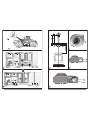
5 - Adjustment and final fixing of the hood (fig. 17)
Two adjustable connectors are provided at the rear of the hood:
a - Turn the screws V1 until the screws V2 are over the screw holes F2.
b - Adjust the hood vertically and horizontally by turning the screws V2.
c - Turn the screws V1 until the hood is locked against the wall.
d - Insert the plastic plugs (provided with the accessories) into the screw holes F2.
e - Lock the screws fixing the hood canopy C to the chimney A.
4.4- Ducting or recirculation fitting
1 - Ducting fitting
This is possible for all installation modes:
a - Air outlet turned upwards; remove the plastic plug from the top part of the outlet vane and
re-fit it at the back (fig. 18). Connect the air outlet to the pipe ducting to the outside using
a rectangular pipe size 70 x 150 mm.
b - Air outlet turned towards the wall; fit the flange F to the outlet vane (see paragraph 4.3
3d), connect the flange to the pipe ducting to the outside using a pipe 120 mm or 150
mm.
c - Air outlet turned to the right or left; fit the spigot R to the outlet vane (see paragraph 4.3
4d), connect the spigot to the pipe ducting to the outside using a rectangular pipe size
70 x 150 mm.
d - Remove the activated charcoal filter (if there is one) from inside the hood canopy (paragraph
3.2 part 2).
2 - Recirculation fitting
This can only be used if the air outlet is turned upwards. Remove the plastic plug from the
top part of the outlet vane and re-fit it at the back (fig. 18). Fit the venting grille G (fig. 19).
The activated charcoal filter inside the hood canopy must only be fitted after electrical
connection.
4.5- Electrical connection and working test
1 - The safety measures 3.2, 3.3 and 3.4 in paragraph 3 are to be strictly observed.
2 - Connect the hood terminals to the motor group terminals (fig. 20).
3 - Once the electrical connection has been completed, check that worktop illumination, motor
and speed work properly.
4 - Replace the grease filters (paragraph 4.2) and, for recirculation fitting only, the activated
charcoal filters (paragraph 3.2, part 2).
Part 2ª - OPERATION AND MAINTENANCE
INSTRUCTIONS
1 - SAFETY WARNINGS
It is most important that all the warnings shown in paragraph 3 of the Installation
instructions are strictly observed.
Moreover, pay special attention to the following warnings during the use and maintenance
of the cooker hood:
1.1- The grease filters and the charcoal filters should be cleaned or replaced as recom-
mended by the manufacturer or more frequently if the hood is used consistently (over
four hours per day).
1.2- When using a gas hob in conjunction with the cooker hood never leave the burners
of the hob uncovered while the hood is in use or when the pans have been removed.
Switch off the gas before removing the pan, or for just short periods and never leave
the hob unattended.
1.3- Always ensure that the flame is kept at a correct intensity to prevent the flame from
licking round from the bottom of the pan; this will save energy and will avoid a
dangerous concentration of heat.
1.4- Always ensure that the appliance is used in accordance with the manufacturer instruc-
tions for the removal of contaminated air and odours during cooking.
88
88
8
99
99
9
ENGLISHENGLISH
ENGLISHENGLISH
ENGLISH
ENGLISHENGLISH
ENGLISHENGLISH
ENGLISH

1ère Partie - INSTRUCTIONS POUR L’INSTALLATION
1 - GENERALITES
Cette hotte est destinée à être installée au mur, au dessus d’un plan de cuisson.
Elle peut être utilisée en version évacuation (raccordement extérieur) ou recyclage (recyclage
interne).
A cause de la complexité et du poids de l’appareil il est préférable que l’installation
soit effectué e par un spécialiste.
La responsabilité du producteur ne saurait être engagée pour tout accident provoqué
par une installation défectueuse.
2 - ELEMENTS
La hotte est composée de (fig. 1):
2.1- 1 corps de hotte C avec commandes et éclairage
2.2- 1 cheminée téléscopique A avec groupe aspirateur
2.3- 1 bride 120 et 150 F
2.4- 1 grille orientée G
2.5- 1 raccord R
2.6- 1 sachet contenant:
1 étrier S pour fixer la cheminée, des vis, tasseaux et documents
3 - CONSEILS CONCERNANT LA SECURITE
3.1- N’utilisez jamais pour le raccordement une cheminée servant de conduit à fumées
(chaudières, cheminées, etc....)
3.2- Verifiez que la tension du secteur soit identique aux valeurs indiquées sur la plaquette
signalétique figurant à l’intérieur de la hotte.
3.3- Reliez la hotte au réseau en interposant un interrupteur bipolaire avec ouverture des
contacts de 3 mm au moins.
3.4- Assurez-vous que l’installation électrique de votre logement ait une mise à la terre
correcte.
3.5- La distance de sûreté minimum entre le plan de cuisson et la hotte est de 65 cm.
3.6- Il est interdit de faire flamber des préparations sous la hotte.
3.7- Lorsque des fritures sont effectuées sous la hotte en fonctionnement, elles doivent
faire l’objet d’une surveillance permanente: l’huile surchauffée pourrait s’enflammer.
3.8- Avant d’effectuer le nettoyage ou l’entretien de la hotte, débranchez l’appareil ou
agissez sur l’interrupteur omnipolaire de votre installation.
3.9- Une ventilation convenable de la pièce doit être prévue si une hotte de cuisine et des
appareils alimentés par une énergie autre que l’énergie électrique évacuent les fumées
simultanément. Une utilisation sans dangers est possible si la dépression maximum
qui se crée dans la pièce est inférieure à 0,04 mbar, ce que évite un retour des gaz
de décharge dans la pièce.
4 - INSTALLATION
Les nombreuses possibilités d’application du groupe aspirateur de cette hotte permettent
quatre diverses façons d’installation.
1 - Sortie de l’air tournée vers le haut (installation filtrante ou aspirante).
2 - Sortie de l’air tournée vers la paroi (uniquement dans l’installation aspirante).
2 - OPERATION
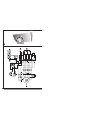
Control panel
The control panel houses the following controls (fig. 21):
SWITCH L = controls worktop illumination.
SWITCH V1 = sets the motor to low speed, to be used to give a continuous light flow of
air when small amounts of steam and vapour are being produced. Noise level
is kept to a minimum.
SWITCH V2 = medium speed, to be used for normal cooking. This speed offers the best
ratio between air capacity and noise level.
SWITCH V3 = top speed, to be used when dealing with high levels of steam or strong
odours, even for a long period.
3 - MAINTENANCE
Regular maintenance and cleaning will ensure good performance and reliability, while ex-
tending the working life of the hood.
Special attention should be paid to the grease filters and to the charcoal filter when the hood
is used in the recirculation mode.
3.1- Metal grease filters
1 - Cleaning
The metal grease filters should be cleaned at least once every two months with normal
usage.
They may be washed in hot water and mild liquid detergent or liquid soap or in a dishwasher.
2 - Removing the filters
See paragraph 4.2. part 1.
3.2- Charcoal filters
1 - Functioning
In the recycling mode the charcoal filters absorb smells and odours.
The charcoal filters cannot be washed and should be replaced at least every 4 months or
more frequently if the hood is used consistently.
2 - Replacing
Remove the grease filters (paragraph 4.2 part 1) and remove the active charcoal filters
pushing on the retaining clips (fig. 22).
Fit new active charcoal and metal grease filters.
ATTENTION: There could be a possible fire hazard if the filters are not cleaned accord-
ing to these instructions.
3.3- Worktop illumination
1 - This is provided by 3 20W halogen lamps.
2 - To replace (fig. 23):
Remove the two screws holding the metal clip, take the lamp out of the lamp holder by
pulling gently. When fitting the new lamp, make sure that the two pins are correctly inserted
in the slots on the lamp holder.
3.4- Cleaning
When cleaning the hood:
- Never use a wet cloth or sponge, or running water.
- Never use thinners or products containing alcohol, as they might damage the paintwork.
- Never use abrasive cleaning materials, in particular when cleaning stainless steel surfaces.
It is recommended to use a damp cloth and mild liquid household cleaner.
1010
1010
10
ENGLISHENGLISH
ENGLISHENGLISH
ENGLISH
FRANÇAISFRANÇAIS
FRANÇAISFRANÇAIS
FRANÇAIS
1111
1111
11

3 - Sortie de l’air tournée vers la droite ou la gauche (uniquement dans l’installation aspirante).
Pour installer correctement la hotte, il faut suivre le schéma suivant:
4.1- Choix du type d’installation
4.2- Fixation de la cheminée A au corps hotte C
4.3- Montage de la hotte à la paroi
4.4- Connexion aspirante ou filtrante
4.5- Branchement électrique et contrôle fonctionnel
4.1- Choix du type d’installation
1 - Sortie de l’air tournée vers le haut (fig. 2a-b)
Dans ce cas, la hotte pourra être utilisée aussi bien dans la version filtrante (fig. 2a) que
dans la version aspirante (fig. 2b).
2 - Sortie de l’air tournée vers la paroi (fig. 3)
Dans ce cas, la hotte ne pourra être utilisée qu’en version aspirante.
3 - Sortie latérale de l’air, à droite ou à gauche
Dans ce cas, la hotte ne peut être utilisée qu’en version aspirante (fig 4a-b).
4.2- Fixation de la cheminée A au corps de hotte C (fig. 5)
La cheminée A avec son groupe aspirateur doit être fixée au corps hotte C:
a - Enlever le filtre métallique en poussant la poignée en acier (fig. 6); remonter en faisant
attention que la poignée soit dans la partie visible.
b - Enlever, si présent, le filtre au charbon actif (paragraphe 3.2, 2ème partie).
c - Positionner les languettes de la cheminée A en correspondance des languettes de fixation
du corps de hotte C, en tenant compte du fait que le guidage de coulissement des deux
cheminées doit être tourné vers la paroi (fig. 7a).
d - Fixer le corps de hotte et la cheminée avec les 4 vis fournies, les languettes du corps
de hotte C sont munies de trous à fente qui permettent un léger réglage en rotation par
rapport à la cheminée (fig. 7b), donc pour une correcte installation, les vis de fixation ne
doivent être serrées définitivament qu’après avoir fixé la hotte à la paroi.
De plus, il faudra raccorder les connexions du corps de hotte (dont la position est
indiquée par une étiquette adhésive) aux connexions du moteur (paragraphe 4.5).
Le filtre métallique et le filtre au charbon actif seront remontés après avoir fixé définitivement
la hotte à la paroi.
S’il y a des étagères en bois dans la zone de montage, avant de fixer la cheminée
au corps de hotte, voir paragraphe 4.3 alinéa 1.
4.3- Montage de la hotte à la paroi
Quel que soit le type d’installation à faire, s’il y a des étagères en bois dans la zone
prédisposée pour monter la hotte, il faudra les enlever, les percer si nécessaire et ensuite
les remonter.
1 - Perçage des étagères:
a - Etagère inférieure (fig. 8)
A l’aide du gabarit en carton, en prenant comme référence le trou “B”, effectuer le
perçage de l’étagère le long de l’axe central pour le passage de la cheminée. La cheminée
doit être introduite dans l’étagère avant la fixation avec le corps de hotte C.
b - Etagère supérieure (fig. 9)
Elle ne devra être percée que pour l’installation avec la sortie de l’air tournée vers le haut.
A l’aide du gabarit en carton, en prenant comme référence le trou “B”, effectuer le
perçage de l’étagère le long de l’axe central pour le passage de la cheminée.
2 - Installation avec la sortie de l’air tournée vers le haut:
a - A l’aide du gabarit en carton, marquer sur la paroi les centres des trous 1 pour fixer le
corps de hotte C. Les trous pour fixer la cheminée doivent être faits à une distance X
de l’entretoise des trous 1, obtenue en mesurant l’extension de la cheminée nécessaire
pour l’installation Z plus 15 mm (fig. 10) X = Z + 15 mm. Avec un foret 8 mm, percer
les centres marqués et introduire les tasseaux fournis.
b - Fixer à fond dans les trous 1 les vis avec bague fournies dans les accessoires.
c - Fixer l’étrier S dans la partie supérieure de la cheminée (fig. 11).
d - Dans le cas de la version aspirante, monter dans la sortie de l’air un tuyau rectangulaire
70 x 150 que l’installateur doit repérer (voir paragraphe 4.4 1a).
Dans le cas de la version filtrante, monter la grille orientée G (voir paragraphe 4.4 2).
e - Accrocher la hotte aux bagues et fixer l’étrier S à la paroi avec deux vis 4,2 x 44,4
fournies.
Pour la fixation définitive voir alinéa 5.
3 - Installation avec sortie de l’air tournée vers la paroi:
a - A l’aide du gabarit en carton, marquer sur la paroi les centres des trous 1 pour fixer le
corps de la hotte C. Les trous pour fixer la cheminée doivent être faits à une distance
X de l’entretoise des trous 1, obtenue en mesurant l’extension de la cheminée nécessaire
pour l’installation Z plus 15 mm (fig. 10), X = Z + 15 mm. Avec un foret 8 mm, percer
les centres marqués et introduire les tasseaux fournis.
b - Percer la paroi pour l’évacuation de l’air 120 mm ou 150 mm (voir le diamètre de la bride
F fournie).
c - Fixer à fond, dans les trous 1, les vis avec bague fournies avec les accessoires.
d - Enlever de la sortie de l’air, l’encadrement en plastique fixé avec quatre vis (fig. 12),
monter la bride F 120 ou 150 mm (fig. 13).
e - Accrocher la hotte aux bagues et fixer l’étrier S à la paroi avec deux vis 4,2 x 4,4
fournies.
Pour la fixation définitive voir alinéa 5.
4 - Installation avec sortie latérale de l’air à droite ou à gauche:
a - A l’aide du gabarit en carton, marquer sur la paroi les centres des trous 1 pour fixer le
corps de la hotte C. Les trous pour fixer la cheminée doivent être faits à une distance
X de l’entretoise des trous 1, obtenue sur l’axe A pour la sortie de l’air tournée vers la
droite, obtenue sur l’axe B pour la sortie de l’air orientée vers la gauche. Mesurer
l’extension “Z” de la cheminée, nécessaire pour l’installation de la hotte, la distance X
sera égale à Z + 15 mm (fig. 14). Avec un foret 8 mm, percer les centres marqués et
introduire les tasseaux fournis.
b - Fixer à fond dans les trous 1 les vis avec bague fournies dans les accessoires.
c - L’appareil en série est fourni avec la sortie de l’air orientée vers la partie arrière de la
hotte, pour modifier l’orientation de l’aspirateur vers la droite ou vers la gauche, opérer
comme suit (fig. 15):
- Dévisser les vis V1, tourner l’aspirateur vers la droite ou vers la gauche de 60°, revisser
les vis V1.
- Monter l’étrier S dans la partie droite ou gauche de l’aspirateur avec deux vis V2
fournies avec les accessoires.
d - Enlever les vis qui fixent l’encadrement en plastique sur la sortie de l’air (fig. 12). Monter
le raccord R et revisser les quatre vis enlevées auparavant (fig. 16).
Remonter le couvercle en plastique.
e - Accrocher la hotte aux bagues et fixer l’étrier S à la paroi avec deux vis 4,2 x44,4
fournies.
Pour la fixation définitive voir alinéa 5.
5 - Réglage et fixation de la hotte (fig. 17)
La hotte est fournie dans la partie arrière de deux attaques réglables:
a - Tourner les vis V1 jusqu’à positionner les vis V2 en correspondance des trous d’accès
F2.
b - Régler verticalement et niveler horizontalement la hotte en tournant les vis V2.
c - Tourner les vis V1 jusqu’à serrer la hotte contre la paroi.
d - Introduire les bouchons en plastique (fournis avec les accessoires) dans les trous F2.
FRANÇAISFRANÇAIS
FRANÇAISFRANÇAIS
FRANÇAIS
1212
1212
12
1313
1313
13
FRANÇAISFRANÇAIS
FRANÇAISFRANÇAIS
FRANÇAIS

e - Serrer définitivement les vis pour fixer le corps de hotte C à la cheminée A.
4.4- Connexion aspirante et filtrante
1 - Connexion aspirante
Elle peut être faite pour tous les types d’installation:
a - Sortie de l’air tournée vers le haut: enlever le bouchon en plastique de la partie supérieure
du diffuseur et le remonter dans la partie arrière (fig. 18). Brancher la sortie de l’air aux
tuyaux d’évacuation externe à travers un tuyau rectangulaire 70 x 150 mm.
b - Sortie de l’air tournée vers la paroi: monter à la sortie du diffuseur la bride F (voir
paragraphe 4.3 3d), brancher la bride aux tuyaux d’évacuation à travers un tuyau 120
ou 150 mm.
c - Sortie latérale de l’air, monter à la sortie du diffuseur le raccord R (voir paragraphe 4,3
4d), brancher le raccord au tuyau d’évacuation à travers un tuyau rectangulaire 70 x 150
mm.
d - Enlever l’éventuel filtre au charbon actif placé à l’intérieur du corps de hotte (paragraphe
3.2, 2ème partie).
2 - Connexion filtrante
Elle ne peut être faite que dans le cas de sortie de l’air orientée vers le haut.
Enlever le bouchon en plastique de la partie supérieure du diffuseur et le remonter dans la
partie arrière (fig. 18). Monter la grille orientée G (fig. 19). Le filtre au charbon actif à
l’intérieur du corps de hotte doit être monté après avoir effectué le branchement électrique.
4.5- Branchement électrique et contrôle fonctionnel
1 - Il faut scrupuleusement respecter les instructions 3.2, 3.3 et 3.4 du paragraphe 3 relatives
à la sécurité.
2 - Brancher la connexion de la hotte à la connexion du groupe moteur (fig. 20).
3 - Après avoir effectué le branchement électrique, vérifier le fonctionnement correct de l’éclairage,
l’allumage du moteur et le changement des vitesses.
4 - Remonter les filtres anti-graisse (paragraphe 4.2) et, uniquement pour la version filtrante, les
filtres au charbon actif (paragraphe 3.2, 2ème partie).
2ème Partie - INSTRUCTIONS POUR L’UTILISATION
ET L’ENTRETIEN
1 - CONSEILS CONCERNANT LA SECURITE
Il est absolument nécessaire de respecter tous les avertissements du paragraphe 3 de
la première partie - Instructions pour l’installation.
En outre, il est très important de faire attention, lors de l’utilisation et de l’entretien, aux
avertissements suivants:
1.1- Effectuer un scrupuleux et régulier entretien des filtres à graisses et à charbon actif
selon les intervalles conseillées par le fabricant, ou plus souvent, pour une utilisation
particulièrement intense (plus de 4 heures par jour).
1.2- Ne laissez jamais de flammes libres à forte intensité sous la hotte en fonctionnement:
en retirant les marmites, éteignez la flamme ou du moins, pour de courtes périodes
et sous surveillance, tenez-la au minimum.
1.3- Réglez toujours la flamme de façon à éviter une fuite latérale de la même par rapport
au fond des marmites: vous économisez de l’énergie et vous évitez de dangereuses
concentrations de chaleur.
1.4- N’utilisez jamais incorrectement votre appareil, qui est destiné uniquement à abattre
les odeurs dans la cuisine.
2 - UTILISATION
Tableau des commandes
Le schéma de commandes est le suivant (fig. 21):
TOUCHE 1 = Allume et éteint le circuit d’éclairage.
TOUCHE V1 = Allume et éteint le moteur en première vitesse, appropriée à un changement
d’air continu particulièrement silencieux, en présence de quelques vapeurs
de cuisson.
TOUCHE V2 = Deuxième vitesse adaptée à la plupart des conditions d’utilisation vu l’excellent
rapport entre débit d’air et niveau de bruit.
TOUCHE V3 = Troisième vitesse adaptée à faire face aux émissions maximum des vapeurs
de cuisson même pendant des temps prolongés.
3 - ENTRETIEN
Un entretien régulier de votre hotte est la garantie d’un bon fonctionnement et d’un bon
rendement.
Des attentions particulières sont à adresser aux filtres à graisses métalliques et, pour les
seules hottes filtrantes, aux filtres à charbon actif.
3.1- Filtres à graisses métalliques
1 - Nettoyage
Il faut laver ces filtres, au maximum, tous les deux mois, avec un normal détergent ménager;
leur dimension compacte permet le lavage même dans le lave-vaisselle.
2 - Démontage des filtres
Voir paragraphe 4.2, 1ère partie.
3.2- Filtres à charbon actif
1 - Fonctionnement
Les filtres à charbon actif ont la capacité de retenir les odeurs jusqu’à la saturation.
Ils ne sont pas lavables et ne peuvent être régénérés; par conséquence, ils doivent être
changés tous les quatre mois ou plus souvent, selon la fréquence d’utilisation.
2 - Remplacement
Enlever les filtres à graisses (paragraphe 4.2, 1ère partie) et enlever les filtres à charbon
actif de leur logement en agissant sur les attaques spéciales (fig. 22).
Remonter les filtres neufs au charbon actif et les filtres à graisse métalliques.
ATTENTION: Afin d’éviter des risques d’incendie provoqués par une accumulation de
graisse dans les filtres, il est nécessaire de respecter les conseils d’entretien et de
remplacement.
3.3- Eclairage
1 - Il est constitué de 3 spots halogènes à 20W.
2 - Remplacement (fig. 23)
Enlever les deux vis qui fixent la douille métallique, extraire le spot du porte-ampoule en
exerçant une légère traction. Pour le remonter, il faut faire attention à introduire correctement
les deux fiches dans le logement du porte-ampoules.
3.4- Nettoyage
Pour le nettoyage normal de la hotte:
- N’utiliser ni chiffons ni éponges mouillés ni jets d’eau.
- Ne pas utiliser de diluants ou d’alcools car ceux-ci pourraient rendre mates les surfaces
vernies.
- Ne pas utiliser de substances abrasives surtout sur les surfaces en acier inox.
On conseille d’utiliser un chiffon humide et un détergent liquide neutre.
FRANÇAISFRANÇAIS
FRANÇAISFRANÇAIS
FRANÇAIS
1414
1414
14
1515
1515
15
FRANÇAISFRANÇAIS
FRANÇAISFRANÇAIS
FRANÇAIS

3838
3838
38
3939
3939
39

4040
4040
40
4141
4141
41

4242
4242
42
4343
4343
43

4444
4444
44
-
 1
1
-
 2
2
-
 3
3
-
 4
4
-
 5
5
-
 6
6
-
 7
7
-
 8
8
-
 9
9
-
 10
10


Robin Safir Murale 900 Operating Instructions Manual
- Catégorie
- Hottes
- Taper
- Operating Instructions Manual
dans d''autres langues
- English: Robin Safir Murale 900
Autres documents
-
Zanussi ZHC916X Manuel utilisateur
-
 De Dietrich HE8975E3 Le manuel du propriétaire
-
Whirlpool AKR 809 UK MR Mode d'emploi
-
 De Dietrich HL8953E2 Le manuel du propriétaire
-
 De Dietrich HV8936E2 Le manuel du propriétaire
-
Falcon Canopy hood Manuel utilisateur
-
 Kuppersbusch USA KD 6500.1 Manuel utilisateur
-
 De Dietrich HK8953E1 Le manuel du propriétaire
-
 De Dietrich HW3635E2 Le manuel du propriétaire
-
Aeg-Electrolux DD8692-M Manuel utilisateur


