Rheem 40-I-M Manuel utilisateur
- Catégorie
- Accessoires de piscine hors terre
- Taper
- Manuel utilisateur
Ce manuel convient également à

Catalog No. 6100.64A
Eective: 02-15-20
Replaces: New
P/N 241827 Rev 1
INSTALLATION
AND OPERATION
MANUAL
FOR YOUR SAFETY: Do not store or use gasoline or other ammable vapors and
liquids or other combustible materials in the vicinity of this or any other appliance. To
do so may result in an explosion or re.
Crosswind
Side Discharge
Heat Pump Pool Heater
NOTE: The instructions in this manual are for the use of qualied individuals specially trained and experienced
in the installation and maintenance of this type of equipment and related system components. Installation and
service personnel are required by some states to be licensed. Persons not qualied shall not attempt to install,
service, or maintain this equipment.
This manual should be maintained in legible condition and kept adjacent to the heat pump pool heater or in a
safe place for future use.
Inverter Models
CROSSWIND-30-I through -65-I
On/O Models
CROSSWIND-40-O through -65-O
(Canada Only)

2
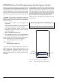
While your unit is being installed by your professional and
licensed installer of choice, please take this opportunity to
quickly register your unit. With the necessary information
in hand, registering your new heat pump pool heater
only takes a few moments and is the best way to ensure
ecient warranty support during the warranty time frame.
See Figure 1 at the bottom of the page to locate and
record your model and serial number. Once you have
done this, please make sure you also have the following
information on hand:
• Name, phone number, and email address of
homeowner.
• Physical address of where the unit is installed; please
include any ‘subdivision’ or similar information.
• Any service challenges present at the house/
neighborhood: gated community, locked access at
house, guard dog, etc.
• Date of installation of the new unit.
• Name and phone number of the professional and
licensed entity that performed the installation for you.
With all of the above information in hand, please contact
us and ask to register your brand new heat pump,
(800)-260-2758 M-F 8:30 - 4:30 EST
or do this online at:
http://warranty.raypak.com
You will be given a Warranty Registration Conrmation
number which you should notate and keep in an
easily remembered accessible location along with
your Installation and Operation Manual, a copy of your
warranty (provided with your manual) and the above
information.
Warranty Registration Conrmation #:
ATTENTION: Please Take This Opportunity to Quickly Register Your Unit
This would also be a good time to review both the manual
and the warranty so that you are aware of how to correctly
operate your new equipment as well as how to keep from
voiding any aspects of your warranty. During the life of
your unit, please feel free to use the phone number on
the last page below to contact us with any questions you
may have about operation, warranty, and/or service.
Thank you very much choosing us to satisfy your pool
heating needs.
0000000000000000
NAME PLATE
BARCODE
SERIAL NUMBER
F10759
For location of this label on your unit, see Figure 8
Figure 1. Model and Serial Number Information

3
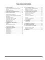
CONTENTS
1. WARNINGS ............................................................. 4
Pay Attention to These Terms .................................4
General Precautions ...............................................5
2. WATER CHEMISTRY ............................................. 5
3. BEFORE INSTALLATION ...................................... 6
Installation Considerations ......................................6
Automatic Chlorinators and Chemical Feeders.......6
Installation Requirements........................................7
Components for Inverter Models .............................9
Components for On/O Models ..............................9
Specications and Dimensions .............................10
Water Connections ................................................ 11
4. ELECTRICAL WIRING ......................................... 13
Wiring .................................................................... 13
Electrical Connections...........................................13
Automation Control, ..............................................13
5. WIRING DIAGRAMS ............................................ 14
Crosswind-30-I, 50-I ..............................................14
Crosswind-40-I ...................................................... 15
Crosswind-65-I ...................................................... 16
Crosswind-40-O ....................................................17
Crosswind-50-O ....................................................18
Crosswind-65-O ....................................................19
6. CONTROLS ........................................................... 20
Inverter Models Only ............................................. 20
On/O Models Only ...............................................21
Using the On/O Display Unit ...............................21
7. OPERATING INSTRUCTIONS ............................ 22
Start-Up Procedures .............................................22
Before Start-Up .....................................................22
Starting ..................................................................22
After Start-Up ........................................................22
Maintenance..........................................................23
Cold Weather Operation .......................................23
Testing ................................................................... 23
8. TROUBLESHOOTING ......................................... 24
Fault Codes ...........................................................24
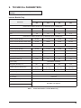
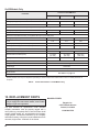
9. TECHNICAL PARAMETERS .............................. 25
10. REPLACEMENT PARTS ..................................... 26
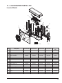
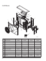
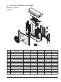
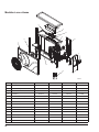
11. ILLUSTRATED PARTS LIST ............................... 27
Inverter Models .....................................................27
On/O Models ....................................................... 28
12. WARRANTY .......................................................... 29

4
1. WARNINGS
Pay Attention to These Terms
A
DANGER
Indicates the presence of immediate hazards which will cause severe personal injury, death or
substantial property damage if ignored.
A
WARNING
Indicates the presence of hazards or unsafe practices which could cause severe personal injury,
death or substantial property damage if ignored.
A
CAUTION
Indicates the presence of hazards or unsafe practices which could cause minor personal injury
or product or property damage if ignored.
CAUTION
CAUTION used without the warning alert symbol indicates a potentially hazardous condition
which could cause minor personal injury or product or property damage if ignored.
NOTE
Indicates special instructions on installation, operation, or maintenance which are important but
not related to personal injury hazards.
A
CAUTION: Improper chemical content in a swimming
pool or spa can damage the heat pump pool heater. DO
NOT add pool/spa chemicals to the pool/spa via the
skimmer or any other apparatus (feeder, chlorinator, etc.)
That is on the inuent side (i.e. inow side) of the heater.
This will damage the heat pump pool heater and could
void the heat pump pool heater warranty. ALWAYS follow
the product manufacturer’s directions when adding any
chemicals to your pool.
A
CAUTION: These heat pump pool heaters are
charged with R-410A refrigerant. Ensure that all service
work is done with gauges and equipment suitable for
R-410A.
A
WARNING: This pool/spa heat pump pool heater
is an electromechanical machine that incorporates a
pressurized refrigerant gas in a sealed system. ONLY
trained and qualied service personnel are authorized to
install or service this equipment. Without proper training
and knowledge of such equipment, any attempt to install
or service the unit could result in serious injury or even
death.
A
CAUTION: Please do not place hands into the outlet
of the swimming pool heater, and do not remove the
heater fan screen at any time.
A
CAUTION: Elevated water temperature can
be hazardous. The U.S. Consumer Product Safety
Commission has these guidelines:
1. Spa water temperatures should never exceed 104°F
(40°C). A temperature of 100°F (38°C) is considered
safe for a healthy adult. Special caution is suggested
for young children.
2. Drinking of alcoholic beverages before or during spa
or hot tub use can cause drowsiness which could
lead to unconsciousness and subsequently result in
drowning.
3. Pregnant Women Beware! Soaking in water over
102°F (39°C) can cause fetal damage during the rst
three months of pregnancy resulting in the birth of a
brain-damaged or deformed child.
4. Before entering the spa or hot tub, users should
check the water temperature with an accurate
thermometer; spa or hot tub thermostats may err
in regulating water temperatures by as much as 4°F
(2.2°C).
5. Persons with a medical history of heart disease,
circulatory problems, diabetes, or blood pressure
problems should obtain a physician’s advice before
using pools or hot tubs.
6. Persons taking medications which induce
drowsiness, such as tranquilizers, antihistamines,
or anticoagulants, should not use spas or hot tubs.

5
General Precautions
Attention
1. Follow the instructions to set a comfortable water
temperature and avoid overheating.
2. Please don’t stack anything near the heat pump
that can block air flow to the inlet or exhaust area,
or the efficiency of the heater will be reduced
and/or stopped. For unit clearance information,
see Figure 2.
3. Please do not put hands into the outlet of the heater,
and do not remove the screen of the fan at any time.
4. If there are abnormal conditions such as noise,
smell, smoke, or electrical leakage, please switch off
the heater immediately and contact the local dealer.
Don’t try to repair it yourself.
5. Do not use or stock combustible gas or liquid such
as thinners, paint and fuel close the heater in order
to avoid fire.
6. The piping between the pool and the heater should
be less than 30 ft (9.1 m) long, or heater performance
may suffer.
Safety
1. Please keep the main power supply switch far away
from children.
2. If a power outage happens while the heater is running,
the heater will restart automatically when power is
restored. Please switch off the power supply when
there is a power outage, and reset the temperature
when power is restored.
3. Please switch off the main power supply in the event
of lightning and stormy weather to prevent machine
damage from a lightning strike.
4. If the heater is stopped for a long time, please cut
off the power supply and drain water completely from
the heater by opening the union of the inlet pipe.
Special Attention
Please read this instruction manual carefully and operate
strictly according to the user manual before starting the
heat pump, otherwise the heat pump may be damaged or
cause you unnecessary harm.
This product is only for heating swimming pool or spa
water, and cannot be used for other applications.
Inlet and outlet water nozzles are not designed to bear the
weight of external pipes. Support the piping independently.
Make sure power is turned o before opening the case and
performing service work.
1. The heater must be installed by a qualified electrician.
2. Set heating temperature within the recommended
range to maximize comfort.
3. Keep the air inlet and exhaust free from obstructions.
4. This heater has a power-off memory function.
5. When the ambient temperature is at or below 32°F
(0°C) make sure the main power switch is turned off
and all water is drained from the heat exchanger.
6. Never place your hand or any other object into the air
inlet or exhaust of the heater.
7. If you see, hear, smell or otherwise sense anything
unusual (such as abnormal noise, smell, smoke, or
electrical leakage) switch off the main power switch
immediately and contact your local dealer installer.
8. Do not attempt to repair the heater yourself.
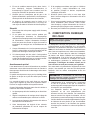
2. WATER CHEMISTRY
NOTE: Corrosive water causes damages which will not
be covered under warranty.
Chemical imbalance can cause severe damage to your
heater and associated equipment. Maintain your water
chemistry according to Table A. If the mineral content
and dissolved solids in the water become too high, scale
forms inside the heat exchanger tubes, reducing heater
eciency and damaging the heater. If the pH drops below
7.2, this will cause corrosion of the heat exchanger and
severely damage the heater. Heat exchanger damage
resulting from corrosive water will not be covered by
the warranty.
For your health and the protection of your pool equipment,
it is essential that your water be chemically balanced. The
following levels must be used as a guide for balanced
water.
A
CAUTION: Free chlorine must not exceed 5 ppm
which can damage the heater and is not covered under
warranty.
• Occasional chemical shock dosing of the pool or spa
water should not damage the heater providing the
water is balanced.
• Automatic chemical dosing devices and salt
chlorinators are usually more efficient in heated
water. Unless controlled, they can lead to excessively
high chlorine levels which can damage your heater.
• Further advice should be obtained from your pool
or spa builder, accredited pool shop, or chemical
supplier for the correct levels needed for your pool.

6
Automatic Chlorinators
and Chemical Feeders
All chemicals must be introduced and completely diluted in
the pool or spa water before being circulated through the
heater. Do not place sanitizing chemicals in the skimmer.
High chemical concentrations will result when the pump is
not running (e.g. overnight).
Table A. Pool Water Chemistry
3. BEFORE INSTALLATION
A
WARNING: This heat pump pool heater is an
electromechanical machine that incorporates a
pressurized refrigerant gas in a sealed system. ONLY
trained and qualied service personnel are authorized to
install or service this equipment. Without proper training
and knowledge of such equipment, any attempt to install
or service the unit could result in serious injury or even
death.
This manual contains important information on the use,
maintenance and troubleshooting of your new heat pump
pool heater. This unit must be properly installed, maintained
and operated for optimal performance.
This heater is an extremely ecient, economical machine
designed specically for pool heating. It is similar in design
and operation to a typical residential air conditioning
system. The unit employs a hermetic motor/compressor
operating in a refrigeration cycle to extract heat from
ambient air and deliver it to the circulating pool water.
As with all heat pump pool heaters, and compared to
other types of heaters such as gas or oil-red, this heater
has lower BTU/hr heating capacity. As a result, it will be
required to operate longer to accomplish the desired
results. It may, at certain times, operate as much as 24
hours per day. However, this should not be of concern
to the owner, because the unit is designed to operate
continuously. Even though it may operate continuously for
many hours, it will still heat the pool with greater economy
than other types of fossil fuel heaters.
Place a recommended cover over the pool at night and
other non-use periods. This will keep evaporation, the
main cause of main heat loss, to a minimum, and will
greatly reduce pool heating costs. During warmer weather,
the cover may be required only at night.
INSTALLATION
Installation Considerations
Locate the heater carefully to minimize installation costs
while providing maximum eciency of operation, and to
allow adequate service access, as follows:
For unrestricted air intake and service access, position
each side of the unit according to Figure 2.
A
WARNING: This unit is designed for outdoor
installation; DO NOT install it in an enclosed area such
as a shed or garage.
To minimize water piping, locate the unit as close as
possible to the existing pool pump and lter.
Irrigation water should be directed away from the heater as
irrigation water spray can damage the heater.
Rain water run os - the unit is designed to operate
outdoors and can be exposed to rain. However, rain water
run o falling directly onto the unit can cause damage and/
or shorten the life of your unit. This may also void your
warranty. Install rain gutters or rain diverters on your roof
if the unit is installed in a position where contact with rain
run o may occur.
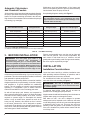
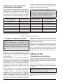
Recommended Level(s) Fiberglass Pools Fiberglass Spas Other Pool and Spa Types
Water Temperature 68-88°F (20-31°C) 89-104°F (31-40°C) 68-104°F (20-40°C)
pH 7.3-7.4 7.3-7.4 7.6-7.8
Total Alkalinity (ppm) 120-150 120-150 80-120
Calcium Hardness (ppm) 200-300 150-200 200-400
Salt (ppm) 4500 Maximum 4500 Maximum 4500 Maximum
Free Chlorine (ppm)* 2-3 2-3 2-3
Total Dissolved Solids (ppm) 3000 Maximum** 3000 Maximum** 3000 Maximum**
*Free Chlorine MUST NOT EXCEED 5 ppm!
**In saltwater chlorinated pools, the total TDS can be as high as 6000 ppm.
Chlorinators must feed downstream of the heater and
have an anti-siphoning device to prevent chemical backup
into the heater when the pump is shut o.
See plumbing diagrams starting with Figure 9.
NOTE: High chemical concentrates from feeders
and chlorinators that are out of adjustment will cause
rapid corrosion to heat exchanger. Such damage is not
covered under the warranty.

7
A
WARNING: Do not install the unit within 3 ft (0.9 m)
of fossil-fuel-burning heaters. Air intake along the sides
of this heater could disturb the combustion process of
the unit, and could cause damage or personal injury.
Mount the unit on a level, sturdy base, preferably a
concrete slab. The size of the base should be at least 3 ft
by 3 ft (0.9 m x 0.9 m).
Installation Requirements
The heater must be installed by a pool professional. End
users are not qualied to install the heater. Damage may
occur to the heater or threaten the safety of the user.
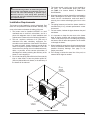
1. The heater must be installed OUTSIDE in a well
ventilated area to avoid air recirculation, and in a
place with adequate room for both installation and
maintenance. Please refer to the following illustration.
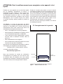
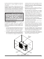
2. This unit requires a minimum of 12" (305 mm) of
clearance from walls, shrubbery, equipment, etc.
around the entire perimeter of the heater. This allows
for ample air intake. Ample clearance around the air
outlet is required to prevent recirculation of air. We
recommend not placing the unit underneath eaves,
decks, or porches, as this causes recirculation of
discharged air, thereby reducing the efficiency of the
heater, or even stopping it.
3. Do not stack anything that will block air flow near the
inlet or outlet areas, or have any barrier within 20"
(508 mm) behind the main heater, or the efficiency of
the heater will be reduced.
4. The heater needs a pool pump (to be supplied by
the user). For recommended pump flow rates,
see Table J for Inverter Models, or Table K for
On/Off Models.
5. When the heater is running, there will be condensation
water discharged at the base. Place the drainage
nozzle into the condensation outlet and attach it
securely, then contact a drainage pipe from it to the
drain.
6. The piping between pool and the heater should be
less than 30 ft (9.1 m), or heater performance cannot
be ensured.
7. For best results, insulate the pipes between the pool
and heater.
8. It is important to keep the area next to the heater
clear of shrubs, bushes and chemicals containers.
These could prevent air from circulating fully through
the heater, and will aect the operation of the heater
or damage the heater.
9. When installed in areas where freezing temperatures
can be encountered, drain the water circuit to prevent
possible freeze-up damage. See page 23 for
proper procedures.
10. If the heater is below the water line of the pool, an
external WFS might be needed.
12"
(305 mm)
MINIMUM
VERTICAL
CLEARANCE
12"
(305 mm)
MINIMUM
12"
(305 mm)
MINIMUM
59"
(1500 mm)
MINIMUM
12"
(305 mm)
MINIMUM
F10762
Figure 2. Ventilation Clearances

8
GAS
HEATER
3 FT
(0.9 m)
MIN
AIR
FLOW
60" (1.52 m) MIN
12"
(0.3 m)
MIN
F10771
Figure 3. Installation Clearances
Inverter Models 60Hz (Heating and Cooling)
Models Raypak P/N Rheem P/N RUUD P/N Jacuzzi P/N
CROSSWIND-30-I 17738 17742 17746 17750
CROSSWIND-40-I 17739 17743 17747 17751
CROSSWIND-50-I 17740 17744 17748 17752
CROSSWIND-65-I 17741 17745 17749 17753
On/O Models 60Hz (Heating and Cooling)
Models Raypak P/N Rheem P/N RUUD P/N Jacuzzi P/N
CROSSWIND-40-O 18122 18125 18128 18131
CROSSWIND-50-O 18123 18126 18129 18132
CROSSWIND-65-O 18124 18127 18130 18133
Table B. Model Identication

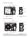
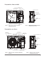
9
FAN
EVAPORATOR
COMPRESSOR
TITANIUM HEAT
EXCHANGER
REACTOR
4-WAY VALVE
EXPANSION VALVE
HIGH AND LOW
PRESSURE VALVE
LOW PRESSURE
PROTECTION SWITCH
WATER FLOW
SWITCH
HIGH PRESSURE
PROTECTION SWITCH
F10754
TOUCH CONTROLLER
UNION
WATER OUTLET
1-1/2" PVC UNION
WATER INLET
1-1/2" PVC UNION
Figure 4. Inverter Model - Component Locations,
Front View
Figure 5. Inverter Model - Component Locations,
Right Side View
EVAPORATOR
FAN
COMPRESSOR
HIGH AND LOW
PRESSURE VALVE
4-WAY VALVE
WATER
FLOW
SWITCH
FRONT OF
HEAT
PUMP
LED
CONTROLLER
LOW PRESSURE
PROTECTION
SWITCH
HIGH PRESSURE
PROTECTION SWITCH
TITANIUM
HEAT
EXCHANGER
WATER INLET
1-1/2" PVC UNION
LED CONTROLLER
WATER OUTLET
1-1/2" PVC UNION
F10757
Figure 6. On/O Model - Component Locations,
Front View
Figure 7. On/O Model - Component Locations,
Right Side View
Components for Inverter Models
Components for On/O Models

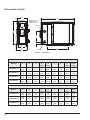
10
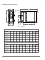
Figure 8. Dimensions
F10755
E
F
G
B
C
H
A
D
SERIAL NUMBER
LABEL LOCATED
HERE
OUTLET
INLET
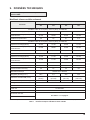
Specications and Dimensions
Inverter Models
Models A B C
D
(Width)
E
(Length)
F G
H
(Height)
Weight
lb (kg)
CROSSWIND-30-I
12.4
(315)
23.2
(312)
12.3
(312)
13.4
(340)
39
(991)
11.4
(290)
2.9
(74)
25.9
(657)
104
(47)
CROSSWIND-40-I
12.4
(315)
23.2
(312)
12.3
(312)
13.4
(340)
39
(991)
11.4
(290)
2.9
(74)
25.9
(657)
106
(48)
CROSSWIND-50-I
12.4
(315)
23.2
(312)
12.3
(312)
13.4
(340)
39
(991)
13
(330)
2.9
(74)
25.9
(657)
115
(52)
CROSSWIND-65-I
15.6
(395)
23.2
(312)
15.4
(390)
16.5
(420)
39
(991)
14.2
(360)
2.9
(74)
25.9
(657)
137
(62)
On/O Models
Models A B C
D
(Width)
E
(Length)
F G
H
(Height)
Weight
lb (kg)
CROSSWIND-40-O
12.4
(315)
23.2
(590)
12.3
(312)
12.4
(315)
39
(991)
11
(280
3
(77)
25.9
(657)
126
(57)
CROSSWIND-50-O
15.6
(395)
24
(610)
15.4
(390)
15.6
(396)
39
(-991)
12.2
(310)
3
(77)
25.9
(657)
150
(68)
CROSSWIND-65-O
15.6
(395)
23.2
(590)
15.2
(387)
15.6
(396)
39
(991)
15
(380)
3
(77)
29.8
(757)
172
(78)
Table C. Basic Product Data - in. (mm)

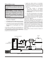
11
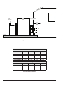
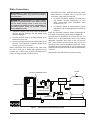
Figure 9. Swimming Pool Heat Pump Piping Layout
WATER TO SWIMMING POOL
SHUT OFF
DIVERTER VALVES
PUMP
FILTER
POOL
WATER IN
DRAINAGE
POWER CORD
OUTLET
INLET
F10772
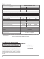
Water Connections
A
CAUTION: The heater inlet and outlet connections
are NOT interchangeable. They must be connected as
instructed below.
A
WARNING: Chemical feeders can result in serious
damage to, or premature failure of the heater and may
void the heater warranty. Install a check valve and/
or a Hartford loop AFTER the heater and BEFORE any
chlorinating devices. Install any automatic chemical
feeders AFTER the heater.
1. Connect the heater in the return water line between
the lter and the pool/spa. See the piping layout
shown in Figure 9.
2. Connect the lter outlet to the tting marked at the
bottom front of the unit.
3. Connect the tting marked to the return piping to the
pool/spa. The inlet/outlet connection ttings of the
unit are 1-1/2 inch PVC unions.
Water connections from the heater to the main return
line can be PVC pipe or exible pipe approved for the
purpose and, in either case, should be at least equal in
size to the main pool/spa circulation piping.
1. Shuto diverter valves, preferably three-way valves
which allows for a bypass route, on the inlet and
outlet lines of the heater are required:
a. to protect (completely bypass) the heater from
any harmful chemical treatments (i.e. acid
wash, back-to-back super chlorinators, stain
treatments, etc.); or
b. to isolate the heater for service/repair or freeze
preparation and still allow pool/spa circulation to
continue.
Install any automatic chemical feeders downstream of
the heater. See the piping layout shown in Figure 9.
Note that some municipalities do not allow the use of a
shuto valve on the euent/outlet side of any heating
equipment, especially when there is one on the inlet
side. These entities typically instead allow a PVC tee
and spring check valve on the euent/outlet side. This is
acceptable and can also double as your protection from
chemical feeders and chlorinators that are downstream
of the unit.
Operate the pump and check the system for leaks.

12
RAYPAK, INC.
GENERAL NOTES:
1. THIS SYSTEM HAS BEEN DESIGNED AND SHALL BE
FABRICATED IN ACCORDANCE WITH THE REQUIREMENTS OF
THE FLORIDA BUILDING CODE SIXTH EDITION (2017). THIS
SYSTEM MAY BE USED WITHIN AND OUTSIDE THE HIGH
VELOCITY HURRICANE ZONE. THIS DESIGN IS NOT
INTENDED TO CERTIFY IMPACT RESISTANCE OF THE
MECHANICAL UNIT CABINETRY.
2. NO 33-1/3% INCREASE IN ALLOWABLE STRESS HAS BEEN
USED IN THE DESIGN OF THIS SYSTEM.
3. ALL DIMENSIONS AND THE MINIMUM WEIGHT (100 LB
MINIMUM) OF MECHANICAL UNIT SHALL CONFORM TO
LIMITATIONS STATED HEREIN. ALL MECHANICAL
SPECIFICATIONS (CLEAR SPACE, TONNAGE, ETC.) SHALL BE
AS PER MANUFACTURER RECOMMENDATIONS AND ARE THE
EXPRESS RESPONSIBILITY OF THE CONTRACTOR.
4. ANCHORS REFERRED TO HEREIN SHALL BE ELCO ULTRACON
SS4 OR ANY EQUIVALENT RATED CAPACITY ANCHOR,
INSTALLED TO 3000 PSI MIN CONCRETE. SEE ANCHOR
SCHEDULE FOR ANCHOR REQUIREMENTS. ALL FASTENERS
SHALL HAVE APPROPRIATE CORROSION PROTECTION TO
PREVENT ELECTROLYSIS.
5. ALL CONCRETE SPECIFIED HEREIN IS NOT PART OF THIS
CERTIFICATION. AS A MINIMUM, ALL CONCRETE SHALL BE
STRUCTURAL CONCRETE 4" MIN. THICK AND SHALL HAVE
MINIMUM COMPRESSIVE STRENGTH OF 3000 PSI, UNLESS
NOTED OTHERWISE.
6. THE CONTRACTOR IS RESPONSIBLE TO INSULATE ALL
MEMBERS FROM DISSIMILAR MATERIALS TO PREVENT
ELECTROLYSIS.
7. ELECTRICAL GROUND, WHEN REQUIRED, TO BE DESIGNED &
INSTALLED BY OTHERS.
8. THE ADEQUACY OF ANY EXISTING STRUCTURE TO
WITHSTAND SUPERIMPOSED LOADS SHALL BE VERIFIED BY
THE ONSITE DESIGN PROFESSIONAL AND IS NOT INCLUDED
IN THIS CERTIFICATION.EXCEPT AS EXPRESSLY PROVIDED
HEREIN, NO ADDITIONAL CERTIFICATIONS OR
AFFIRMATIONS ARE INTENDED.
9. THE SYSTEM DETAILED HEREIN IS GENERIC AND DOES NOT
PROVIDE INFORMATION FOR A SPECIFIC SITE. FOR SITE
CONDITIONS DIFFERENT FROM THE CONDITIONS DETAILED
HEREIN, A LICENSED ENGINEER OR REGISTERED ARCHITECT
SHALL PREPARE SITE SPECIFIC DOCUMENTS FOR USE IN
CONJUNCTION WITH THIS DOCUMENT.
SITE-SPECIFIC PRESSURE REQUIREMENTS AS DETERMINED IN
ACCORDANCE WITH ASCE 7-10 AND CHAPTER 16 OF THE FLORIDA
BUILDING CODE SHALL BE LESS THAN OR EQUAL TO THE DESIGN
PRESSURE CAPACITY VALUES LISTED HEREIN FOR ANY ASSEMBLY
AS SHOWN. DESIGN PRESSURE REQUIREMENTS SHALL BE
DETERMINED BY A REGISTERED DESIGN PROFESSIONAL ON A
JOB-SPECIFIC BASIS IN ACCORDANCE WITH THE GOVERNING
CODE.
DESIGN NOTES:
ANCHOR SCHEDULE:
CONCRETE:
(4" THICK MIN,
3000 PSI MIN.)
SUBSTRATE DESCRIPTION
CROSSWIND-30-I
23.23"
UNIT DIMENSIONS & MODELS:
APPROVED DESIGN
CRITERIA:
50.2 PSF LATERAL
41.2 PSF UPLIFT
WIND LOAD
WIND LOAD EVALUATION OF HEAT PUMP CROSSWIND MODELS: AT GRADE MOUNTED APPLICATIONS
(1)-1/4"Ø ELCO ULTRACON SS4, 1.75" EMBEDDED INTO 3 KSI
CONCRETE, 2.5" MIN. EDGE DISTANCE, 3" MIN. SPACING TO ANY
ADJACENT ANCHOR OR ANY EQUIVALENT RATED CAPACITY ANCHOR.
MECHANICAL UNIT
N.T.S
ISO VIEW
MODELS
"A" "B"
"C"
"D"
23.23"
23.23"
23.23"
12.40"
12.40"
12.40"
15.55"
13.39" 37.83"
13.39"
13.39"
16.54"
37.83"
37.83"
37.83"
"E"
25.91"
"F"
12.29"
WEIGHT
101 LBS
25.91"
25.91"
25.91"
12.29"
12.29"
15.35"
126 LBS
150 LBS
172 LBS
MECHANICAL UNIT
CONCRETE
SUBSTRATE
(BY OTHERS)
CROSSWIND-40-I
CROSSWIND-50-I
CROSSWIND-65-I
SCAN HERE :
OR, GO TO
ECALC.IO/TER
ABOUT THIS DOCUMENT
ENGINEER-CERTIFIED ORIGINALS, VARIATIONS
& MORE INFORMATION CAN BE FOUND BY
VISITING
ENGINEERINGEXPRESS.COM/STORE
OR BY SCANNING OR USING
THE WEB ADDRESS FOUND HERE >
THIS DOCUMENT NOT VALID WITHOUT
ORIGINAL ENGINEER CERTIFICATION
CONCRETE SLAB BY
OTHERS, TYP.
N.T.S.
MECHANICAL UNIT
FRONT VIEW
"D"
"E"
"F"
"E"
N.T.S.
MECHANICAL UNIT
FRONT VIEW
MECHANICAL UNIT
(SEE MODEL IN TABLE)
N.T.S. ELEVATION
TIE-DOWN DETAIL
UNIT BASE
RAIL
MECHANICAL
UNIT
CONCRETE SLAB
(BY OTHERS)
SEE CONCRETE SCHEDULE FOR
ANCHOR SPECIFICATIONS
MECHANICAL
UNIT
N.T.S.
TIE-DOWN LAYOUT
PLAN
"B"
"A"
"C"
"D"
Figure 10. Hurricane Tie Down Instructions
See "Table C. Basic Product Data - in. (mm)"
on page 10 for dimensions and weights.

13
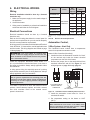
4. ELECTRICAL WIRING
Wiring
Electrical installation should be done by a licensed
electrician only.
1. Make sure the power supply is at the rated voltage of
the appliance.
2. Ground the heater.
3. Wiring must be installed by a professional installation
technician and follow the circuit diagram.
Electrical Connections
Electrical installation should be done by a licensed
electrician only.
Refer to the unit rating plate below the control panel for
precise power requirements for your unit, and for ampacity
and over-current protection requirements.
All wiring must be in accordance with the National Electrical
Code, NFPA No. 70, latest edition, and all applicable state
and local codes. The wiring diagrams are located on page
14 through page 18.
A
WARNING: This heater MUST be installed using
exible conduit for supply wiring to the unit. This will
allow movement of the conduit whenever the junction
box is removed for service.
Locate the equipment disconnect means within 3 ft.
(0.9 m) of the heater’s electrical enclosure, or as close to
the heater as possible. Always satisfy applicable codes
and standards.
In sizing power wiring, be especially aware of up-sizing
requirements necessary due to wiring distances. Always
satisfy applicable codes and standards.
NOTE: Refer to the National Electrical Code, Article
680, for general requirements for swimming pools and
equipment, and to Article 440 for special considerations
necessary for circuits supplying hermetic refrigeration
motor/compressors.
This heater is pre-wired to work with external control
systems, heat-on-demand options, and other external
time clock overrides. Refer to the external control
system’s instructions.
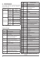
Models Power
Min.
Circuit
Ampacity
Breaker Size
(Amp)
min. max.
CROSSWIND-30-I
208-230VAC
60HZ/1PH
12A 15A 15A
CROSSWIND-40-I
12A 15A 15A
CROSSWIND-50-I
16A 20A 20A
CROSSWIND-65-I
20A 20A 25A
CROSSWIND-40-O
12A 15A 15A
CROSSWIND-50-O
16A 20A 20A
CROSSWIND-65-O
17.2A 25A 25A
* Reference only - see National Electric Code or local codes for wire gauge length
limits.
Table D. Electrical Power Requirements
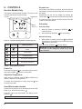
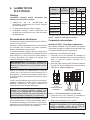
Automation Control,
2-Wire System - Heat Only
The Crosswind inverter models have a temperatures
sensor for temperature automation control.
Heater 2-Wire Controllers (Heat Only)
1. Install wires from the automation controller for “Heat”
on the terminal strip inside the heater electrical
compartment on the side of the heater.
2. Remove the jumper wire on the terminal block from
terminals marked #5 and #6. See Figure 11, and
wiring diagrams on page 14 through page 19.
L1 L2 P1 P2
5 6
PUMP CONTROLPOWER
208 -230V/60HZ
CUSTOMER REMOTE
CONTROL SWITCH
CONNECTOR
YLW/GRN
Figure 11. Automation Control 2-Wire System Connection
3. Install the automation control wires for “Heat” to
terminals #5 and #6.
4. Set temperature setting on the heater to 104°F
(40°C).
NOTE: When the automation controller has a
HEAT command the unit will be in the HEAT mode.
When the automation controller does not have a HEAT
command the unit will be in the OFF mode.

14
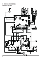
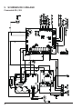
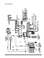
5. WIRING DIAGRAMS
Crosswind-30-I, 50-I

15
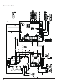
Crosswind-40-I

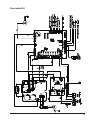
16
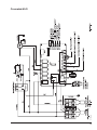
Crosswind-65-I

17
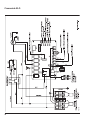
F10766
Crosswind-40-O

18
F10767
Crosswind-50-O

19
Crosswind-65-O

20
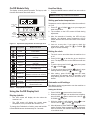
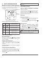
6. CONTROLS
Inverter Models Only
The Display controls general operation. The layout, main
functions and buttons are shown below.
HEATING
CAPACITY %
COMPRESSOR
HEATING
Figure 12. Operation Display, Models -30-I through -65-I
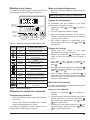
Symbol Designation Button Functions
Press 3 seconds to unlock/lock
screen
ON/OFF Power On/O
Speed Smart/Silent Mode
Up Temperature Adjustment
Down Temperature Adjustment
Table E. Display Button Functions
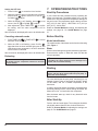
Power On
Press the LOCK button
for 3 seconds to light up screen,
then press POWER to power on the heater.
Adjust/Set Temperature:
When screen is unlocked, press UP or DOWN to
display or adjust the set temperature.
To change from Fahrenheit to Celsius, press the and
the for 3 seconds.
Smart/Silent mode selection
Smart mode, as default, will be activated when the HEAT
PUMP is on, and the screen shows .
Press FAN to enter Silent Mode. The display screen
will show .
NOTE: Select Smart Mode for initial heating.
Screen Lock
If no button is used within 30 seconds, the screen will lock
automatically. At this point the backlight will turn o and 0%
will display.
Alternatively you can lock the display by pressing the
LOCK button
for 3 seconds to achieve the same result.
To unlock the screen and use any other button, follow the
Power On instruction above.
Defrosting
Auto Defrosting:
1. When the heater is defrosting, HEATING will
continually flash.
2. After defrosting, HEATING will stop flashing.
Manual Defrosting:
1. When heater is heating, press FAN and MINUS
together for 5 seconds to start manual defrosting,
will flash continuously.
After defrosting, HEATING will stop ashing.
NOTE: Manual defrosting intervals should be more than
30 minutes and the compressor should run for more
than 10 minutes.
La page est en cours de chargement...
La page est en cours de chargement...
La page est en cours de chargement...
La page est en cours de chargement...
La page est en cours de chargement...
La page est en cours de chargement...
La page est en cours de chargement...
La page est en cours de chargement...
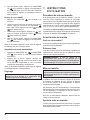
La page est en cours de chargement...
La page est en cours de chargement...
La page est en cours de chargement...
La page est en cours de chargement...
La page est en cours de chargement...
La page est en cours de chargement...
La page est en cours de chargement...
La page est en cours de chargement...
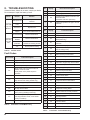
La page est en cours de chargement...
La page est en cours de chargement...
La page est en cours de chargement...
La page est en cours de chargement...
La page est en cours de chargement...
La page est en cours de chargement...
La page est en cours de chargement...
La page est en cours de chargement...
La page est en cours de chargement...
La page est en cours de chargement...
La page est en cours de chargement...
La page est en cours de chargement...
La page est en cours de chargement...
La page est en cours de chargement...
La page est en cours de chargement...
La page est en cours de chargement...
La page est en cours de chargement...
La page est en cours de chargement...
La page est en cours de chargement...
La page est en cours de chargement...
La page est en cours de chargement...
La page est en cours de chargement...
La page est en cours de chargement...
La page est en cours de chargement...
La page est en cours de chargement...
La page est en cours de chargement...
La page est en cours de chargement...
La page est en cours de chargement...
-
 1
1
-
 2
2
-
 3
3
-
 4
4
-
 5
5
-
 6
6
-
 7
7
-
 8
8
-
 9
9
-
 10
10
-
 11
11
-
 12
12
-
 13
13
-
 14
14
-
 15
15
-
 16
16
-
 17
17
-
 18
18
-
 19
19
-
 20
20
-
 21
21
-
 22
22
-
 23
23
-
 24
24
-
 25
25
-
 26
26
-
 27
27
-
 28
28
-
 29
29
-
 30
30
-
 31
31
-
 32
32
-
 33
33
-
 34
34
-
 35
35
-
 36
36
-
 37
37
-
 38
38
-
 39
39
-
 40
40
-
 41
41
-
 42
42
-
 43
43
-
 44
44
-
 45
45
-
 46
46
-
 47
47
-
 48
48
-
 49
49
-
 50
50
-
 51
51
-
 52
52
-
 53
53
-
 54
54
-
 55
55
-
 56
56
-
 57
57
-
 58
58
-
 59
59
-
 60
60
-
 61
61
-
 62
62
-
 63
63
-
 64
64


Rheem 40-I-M Manuel utilisateur
- Catégorie
- Accessoires de piscine hors terre
- Taper
- Manuel utilisateur
- Ce manuel convient également à
dans d''autres langues
- English: Rheem 40-I-M User manual
Documents connexes
Autres documents
-
Raypak 40-I, 50-I, 65-I Manuel utilisateur
-
Fartools RWP 400 Le manuel du propriétaire
-
Waterco Electroheat Pool Heat Pump Mode d'emploi
-
 Nautyl PHCP50 Installation and User Manual
-
BLACK DECKER BD-137 Manuel utilisateur
-
Calorex I-PAC 8-12-16-22 Inverter Swimming Pool Heat Pump Guide d'installation
-
Raypak 268A Professional Pool and Spa Heater Manuel utilisateur
-
Pentair Pool UltraTemp ETi Chauffe-Piscine Hybride Le manuel du propriétaire
-
Zodiac Edenpac 5D Instructions For Installation And Use Manual
-
Jandy LXI Mode d'emploi
