1
IMPORTANT:
Go to www.extron.com for the complete
user guide, installation instructions, and
specifications before connecting the
product to the power source.
SMK V SB 33 VESA Mounting Kit • Setup Guide
Product Description
The SMK V SB 33 VESA Mounting Kit allows the SB 33 A Series speaker to be attached to the same VESA display mount that
supports the display device. This type of installation enables the SB 33 speaker to be aligned with the display for a visually
aesthetic installation. The SB 33 front speaker surface can be adjusted ush with the front of the display. It can be adjusted
forward, backward, up, down, and side-to-side.
Installation
VESA display mounts come in a variety of different styles, so these instructions for installing the SMK V SB 33 VESA Mounting Kit
are variable. Please consult the installation guides for your specic VESA display mount and your display device before installing
our kit. Follow the steps below to install the kit.
WARNING: Risk of personal injury or property damage. The final installation should be able to continuously support
the speaker weight. The final installation should also be able to support short term overloading. Be sure to not exceed the
load limit of the VESA mount, mounting surface, and SMK V SB 33. The maximum load limit of the SMK V SB 33 is 85 lb.
(38 kg) Since applications can vary considerably, it is assumed that the installer will exercise good judgment when selecting
the mounting location, method, and hardware. Installation and service must be performed by authorized personnel only.
AVERTISSEMENT : Risque de dommages corporels ou matériels. L’installation nale doit pouvoir supporter en
permanence le poids de l’enceinte. L’installation nale doit également pouvoir supporter une courte surcharge. Veillez à ne
pas dépasser la charge maximale du support de montage VESA, de la surface de montage, et de l’unité SMK V SB 33. La
charge maximale du SMK V SB 33 est de 38 kg. Étant donné la possibilité d’évolution considérable des applications, il est
supposé que l’installateur fera preuve de discernement lors de la sélection de l’emplacement, du mode, et du matériel de
montage. L’installation et la maintenance du système doivent être exclusivement effectuées par un technicien agréé.
NOTE: Observe all applicable building codes and local ordinances when installing the SB 33 A speaker.
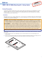
The SMK V SB 33 VESA Mounting Kit is composed of 2 long L-brackets, 2 short L-brackets, 6 bolts, 6 lock washers, 2 washers,
and 6 wingnuts.
1. Install the wall mount portion of the VESA display mount onto the desired wall location. See the VESA display mount
installation guide.
2. Position one long L-bracket of the SB 33 kit on the back of the display while aligning the bolt hole on the display with a slot
on the L-bracket. Repeat this procedure for the other long L-bracket on the other side of the display.
Long L-brackets

2
SMK V SB 33 Kit • Setup Guide (Continued)
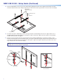
3. Place the VESA display mount on top of the L-bracket while aligning the bolt hole of the display mount with the slot of the
L-bracket and the bolt hole of the display. Repeat this procedure for the other long L-bracket on the other side of the display.
Mounting Screws
VESA Display
Mount (not included)
Long L-brackets
Washers
4. Insert bolts through the VESA display mounts, the long L-brackets, and the display. Be sure to the align the bolt holes of
the VESA display mounts with the display mounting holes and insert the bolts. Tighten all 4 bolts. Spacers are provided if
needed. See the illustration in step 3.
5. Position the short L-bracket under the long L-bracket that was installed in step 4 above such that the L bends of each
bracket are paired together. See the illustration below. Then install 1 bolt with a wingnut and lockwasher (included in the kit)
so that the long L-bracket and short L-bracket are held together. Tighten the wingnut. Repeat this procedure for the other
long L-bracket on the other side of the display.
NOTE: The short L-bracket may be reversed if the SB 33 speaker needs to be positioned further forward relative to the
display above it. See the illustration below right.
Lock
Washer
Wingnut
Short
L-bracket
Bolt
Long
L-bracket
Alternative Installation of
Short L-bracket
Short
L-bracket
(Reversed)

3
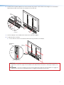
6. Install the SB 33 speaker wallplate to the short L-bracket using 2 bolts, 2 lock washers, and 2 wingnuts, as shown below.
Repeat this procedure for the other short L-bracket on the other side.
Lock
Washer
Wallplate
Wingnut
Short
L-bracket
Bolt
Long
L-bracket
7. Fasten the display onto the VESA wall mount that was attached in step 1.
8. To adjust the SB 33 vertically:
a. Loosen, but do not remove, the bolts that attach the long L-brackets to the display.
Vertical Adjustment
Long
L-bracket
Bolt
VESA Display
Mount
Washer
CAUTION: If the display is already attached to the wall, the display could detach from the VESA mount if this
adjustment is made. It is highly recommended that this adjustment be done prior to attaching the display to the
wall.
ATTENTION: Si l’écran est déjà xé au mur, il peut être détaché du support de montage VESA si ce réglage est
effectué. Il est vivement recommandé d’effectuer ce réglage avant de xer l’écran au mur.

4
SMK V SB 33 Kit • Setup Guide (Continued)
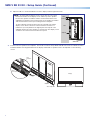
b. Adjust the SB 33 to the desired distance from the display and then tighten the bolts.
NOTE: Assuming that the display screen is level, allow for some space
between the bottom of the display screen and the top of the speaker
because the speaker assemblies and the center bracket attach to the
wallplate by hooking the top mounting clasps of the speaker assemblies
and center bracket over the top mounting rail of the wall plate.
To allow sufficient clearance between the top of the SB 33 A and the
display screen above it, allow for at least a minimum clearance of
0.69 inches (17.5 mm) between the highest part of the top rail of the
wallplate and the top of the speaker, as shown below. The display screen
should not encroach into this area above the top rail.
INPUTS
POWER
MAX
12V
0.7A
OUTPUT
REMOTE
V
L
L
R
LEVEL BASS TREBLE
R
CG
10V 50mA
CLASS 2 WIRING
L SPEAKER
Wallplate
Side View
11/16"
(17.46 mm)
Wall
9. Install the SB 33 A speaker to the wallplate. See the SB 33 A Series Setup Guide and SB 33 A Series User Guide for further
installation details. If the alignment between the display and the SB 33 speaker needs to be adjusted, see the following
section.
Wallplate
Short
L-bracket
Long
L-bracket
SB 33 A Speaker
Display

5
68-3104-50 Rev. A
03 19
For information on safety guidelines, regulatory compliances, EMI/EMF compatibility, accessibility, and related topics, see the
Extron Safety and Regulatory Compliance Guide on the Extron website.
© 2019 Extron Electronics — All rights reserved. www.extron.com
All trademarks mentioned are the property of their respective owners.
Worldwide Headquarters: Extron USA West, 1025 E. Ball Road, Anaheim, CA 92805, 800.633.9876
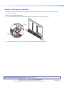
Aligning the SB 33 Speaker to the Display
The SMK V SB 33 VESA Mounting Kit can be adjusted to align the SB 33 speaker assembly relative to the front of the display,
from front to rear (depth).
Front to rear (depth) adjustment
1. Loosen, but do not remove, the 2 wingnuts that attach the long L-brackets to the short L-brackets.
Depth Adjustment
Long
L-bracket
Short
L-bracke
t
2. Adjust the SB 33 either to the front or to the rear of the display and then tighten the wingnuts.
-
 1
1
-
 2
2
-
 3
3
-
 4
4
-
 5
5