3M PROTECTA® Twin-Leg Self Retracting Lifeline Web 3100412, Red, 6 ft. (1.8 m), 1 ea Mode d'emploi
- Taper
- Mode d'emploi
Ce manuel convient également à
- PROTECTA® Rebel™ Self Retracting Lifeline - Web 3100403, Red, 6 ft. (1.8 m)
- PROTECTA® Rebel™ Self Retracting Lifeline, Web 3100400, Red, 6 ft. (1.8 m)
- Protecta® Retracting Lifeline 3100414, Web, Twin legs, Thermoplastic Housing, Rebar Hooks, 6ft (1.8m)
- PROTECTA® Self Retracting Lifeline - Web 3100401, Red, 6 ft. (1.8 m), 1 EA/Case
- PROTECTA® Self Retracting Lifeline - Web 3100402, Red, 6 ft. (1.8 m), 1 EA
- PROTECTA® Self Retracting Lifeline - Web 3100404, Red, 6 ft. (1.8 m), 1 EA
- Protecta® Self Retracting Lifeline 3100405, Web, Thermoplastic Housing, Steel Rebar Hook, 6ft (1.8m)
- PROTECTA® Twin-Leg Self Retracting Lifeline - Web 3100413, Red, 6 ft. (1.8 m), 1 EA

© Copyright 2014, Capital Safety
ANSI Z359.14 Class B
ANSI A10.32
CSA Z259.2.2-98 Type 1
OSHA
This manual is intended to meet the Manufacturer’s
Instructions as required by the above listed standards
and should be used as part of an employee training
program as required by OSHA.
INSTRUCTION MANUAL
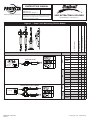
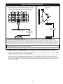
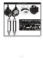
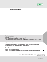
Figure 1 – Rebel™ Self Retracting Lifeline Models
A - Steel Carabiner
B - Steel Snap Hook
C - Steel Swiveling Snap Hook
D - Steel Rebar Hook
Swivel End Lifeline End
Model Swivel End Lifeline End
A - 2000192
(Optional)
Single SRL Models
B
C
D
ANSI
3100400
1
3100401
1
3100402
1
3100403
1 1
3100404
1 1
3100405
1 1
CSA
3100406
1
3100407
1
3100408
1
3100409
1 1
3100410
1 1
3100411
1 1
A - 2000192
Twin SRL Harness Mount Models
B
C
D
ANSI
3100412
1 2
3100413
1 2
3100414
1 2
CSA
3100415
1 2
3100416
1 2
3101257
1 2
Trusted Quality Fall Protection
FORM NO: 5903744
REV: B
SELF RETRACTING LIFELINES
Model Numbers: (See Figure 1)

2
WARNING: This product is part of a personal fall arrest, work positioning, or rescue system. The user must
follow the manufacturer’s instructions for each component of the system. These instructions must be provided
to the user of this equipment. The user must read and understand these instructions before using this
equipment. Manufacturer’s instructions must be followed for proper use and maintenance of this equipment.
Alterations or misuse of this product or failure to follow instructions may result in serious injury or death.
IMPORTANT: If you have questions on the use, care, or suitability of this equipment for your application,
contact Capital Safety.
IMPORTANT: Before using this equipment, record the product identication information from the ID label in
the inspection and maintenance log of this manual.
descRIPTIONs:
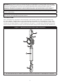
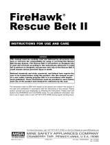
Figure 2 illustrates key components of the base Rebel™ Self Retracting Lifeline (SRL). The Rebel SRLs are 6
ft. (1.8 m) lifelines, equipped with an in-line Load Indicator, which retract into a Thermoplastic Housing. Rebel
SRLs are available in multiple model congurations that allow attachment to an anchorage point, single or dual
mounting on a Full Body Harness, or similar equipment (see Figure 1). The Rebel SRL automatically locks at the
onset of a fall to arrest the fall, but pays out and retracts lifeline during normal movement by the attached user.
Figure 2 – Rebel Self Retracting Lifeline (SRL) Components
B
D
F
G
A
C
E
A - Swivel B -Swivel Eye C - Carabiner (optional) D - Housing E - Web Lifeline F - Load Indicator G - Snap Hook

3
1.0 APPLICATIONS
1.1 PURPOSE: Capital Safety Self Retracting Lifelines (SRLs) are designed to be a component in a personal
fall arrest system (PFAS). Figure 1 illustrates SRLs covered by this instruction manual and their typical
applications. They may be used in most situations where a combination of worker mobility and fall protection
is required (i.e. inspection work, general construction, maintenance work, oil production, conned space
work, etc.).
1.2 STANDARDS: Your SRL conforms to the national standard(s) identied on the front cover of these
instructions. Refer to local, state, and federal (OSHA) requirements governing occupational safety for
additional information regarding Personal Fall Arrest Systems. Refer to the following national standards on fall
protection:
ANSI Z359.0 Denitions and Nomenclature Used for Fall Protection and Fall Arrest
ANSI Z359.1 Safety Requirements for Personal Fall Arrest Systems, Subsystems, and Components
ANSI Z359.2 Minimum Requirements for a Comprehensive Managed Fall Protection Program
ANSI ANSI A10.32 Personal Fall Protection use in Construction and Demolition
1.3 TRAINING: This equipment is intended to be used by persons trained in its correct application and use. It is the
responsibility of the user to assure they are familiar with these instructions and are trained in the correct care and use
of this equipment. Users must also be aware of the operating characteristics, application limits, and the consequences of
improper use.
2.0 LIMITATIONS & REQUIREMENTS
Always consider the following limitations and requirements when installing or using this equipment:
2.1 CAPACITY: SRLs are designed for use by one person with a combined weight (person, clothing, tools, etc.)
not exceeding 310 lbs (140 kg) and at least 75 lbs (34 kg).
At no time shall more than one person connect to a single SRL for fall arrest applications.
2.2 MAXIMUM ARREST FORCE AND MAXIMUM ARREST DISTANCE: SRLs documented in this instruction meet
the following Arrest Force and Arrest Distance maximums:
Weight of Worker Up to 310 lbs (140 kg)
Average Arresting Force 900 lbs (4.0 kN)
Maximum Arresting Force 900 lbs (4.0 kN)
Maximum Arrest Distance 42 in (1.07 m)
2.3 ANCHORAGE: Anchorages selected for fall arrest systems shall have a strength capable of sustaining static
loads applied in the directions permitted by the system of at least:
1. 5,000 lbs. (22.2 kN) for non-certied anchorages, or
2. Two times the maximum arresting force for certied anchorages.
When more than one fall arrest system is attached to an anchorage, the strengths set forth in (1) and (2)
above shall be multiplied by the number of systems attached to the anchorage.
FROM OSHA 1926.500 AND 1910.66: Anchorages used for attachment of personal fall arrest systems shall be
independent of any anchorage being used to support or suspend platforms, and capable of supporting at least 5,000 lbs. per
user attached, or be designed, installed, and used as part of a complete personal fall arrest systems which maintains a safety
factor of at least two, and is under the supervision of a qualied person.
2.4 RESCUE PLAN: When using this equipment, the employer must have a rescue plan and the means at hand
to implement it and communicate that plan to users, authorized persons, and rescuers.
2.5 INSPECTION FREQUENCY:
SRLs shall be inspected by the authorized person
1
or rescuer
2
before each use.
Additionally, inspections shall be conducted by a competent person
3
other than the user, and by a factory
authorized inspection entity. The competent person shall use the Inspection Schedule (Table 1) to determine
appropriate inspection intervals.
Inspection procedures are described in the “Inspection Checklist” (Table 2).
Results of the Competent Person inspection should be recorded in the “Inspection and Maintenance Log” on
the back pages of these instructions.
1 Authorized Person: A person assigned by the employer to perform duties at a location where the person will be exposed to a fall hazard.
2 Rescuer: Person or persons other than the rescue subject acting to perform an assisted rescue by operation of a rescue system.
3 Competent Person: An individual designated by the employer to be responsible for the immediate supervision, implementation, and monitoring of the employ-
er’s managed fall protection program who, through training and knowledge, is capable of identifying, evaluating, and addressing existing and potential fall hazards,
and who has the employer’s authority to take prompt corrective action with regard to such hazards.

4
Table 1 – Inspection Schedule
Type of Use
Application
Examples Conditions of Use
Inspection Frequency
Competent Person User
Infrequent to Light Rescue and
Conned
Space, Factory
Maintenance
Good Storage Conditions, Indoor or Infrequent
Outdoor Use, Room Temperature, Clean
Environments
Annually Before
each use
Moderate to Heavy Transportation,
Residential
Construction,
Utilities,
Warehouse
Fair Storage Conditions, Indoor and Extended
Outdoor Use, All Temperatures, Clean or
Dusty Environments
Semi-Annually
to Annually
Before
each use
Severe to
Continuous
Commercial
Construction, Oil
and Gas, Mining
Harsh Storage Conditions, Prolonged or
Continuous Outdoor Use, All Temperatures,
Dirty Environment
Quarterly to
Semi-Annually
Before
each use
2.6 LOCKING SPEED: Situations which do not allow for an unobstructed fall path should be avoided. Working
in confined or cramped spaces may not allow the body to reach sufficient speed to cause the SRL to lock if a
fall occurs. Working on slowly shifting material, such as sand or grain,may not allow enough speed buildup
to cause the SRL to lock. A clear path is required to assure positive locking of the SRL.
2.7 NORMAL OPERATIONS: Normal operation will allow the full length of the lifeline to extend and retract
with no hesitation when extending and no slack when retracting as the worker moves at normal speeds. If a
fall occurs, a speed sensing brake system will activate, stopping the fall and absorbing much of the energy
created. For falls which occur near the end of the lifeline travel, a reserve lifeline system or Load Indicator
has been incorporated to assure a reduced impact fall arrest. If the SRL has been subjected to fall forces,
remove the SRL from service, mark “UNUSABLE”, and dispose of in the recommended manner (see “Section
5.4 - Disposal”). Sudden or quick movements should be avoided during normal work operation, as this may
cause the SRL to lock up.
2.8 FREE FALL: When anchored overhead, SRLs will limit the free fall distance to 2 ft. (61 cm) or less. To avoid
increased fall distances, anchor the SRL directly above the worker. Avoid working where your lifeline may
cross or tangle with that of another worker. Avoid working where an object may fall and strike the lifeline;
resulting in loss of balance or damage to the lifeline. Do not allow the lifeline to pass under arms or between
legs. Never clamp, knot, or prevent the lifeline from retracting or being taut. Avoid slack line. Do not
lengthen SRL by connecting a lanyard or similar component without consulting Capital Safety.
2.9 FALL CLEARANCE: Figure 3A illustrates Fall Clearance requirements. Ensure adequate clearance exists in the fall
path to prevent striking an object during a fall. If the worker will be working at a position that is not directly below
the SRL anchorage point, the clearance required and vertical fall distance will be greater.
2.10 SWING FALLS: Swing falls occur when the anchorage point is not directly above the point where a fall
occurs (see Figure 3B). The force of striking an object in a swing fall may cause serious injury. In a swing
fall, the total vertical fall distance will be greater than if the user had fallen directly below the anchorage
point, thus increasing fall clearance required to safely arrest the user. Use Figure 3A to determine the fall
clearance for your application. Minimize swing falls by working as directly below the anchorage point as
possible. Never permit a swing fall if injury could occur.
2.11 HAZARDS: Use of this equipment in areas where surrounding hazards exist may require additional precautions to
reduce the possibility of injury to the user or damage to the equipment. Hazards may include, but are not limited
to: high heat, caustic chemicals, corrosive environments, high voltage power lines, explosive or toxic gases,
moving machinery, sharp edges, or overhead materials that may fall and contact the user or fall arrest system.
2.12 SHARP EDGES: Avoid working where the lifeline will be in contact with or abrade against unprotected sharp
edges.
Where contact with a sharp edge is possible, cover the edge with a protective material.
2.13 BODY SUPPORT: A Full Body Harness must be used with the Self Retracting Lifeline. The harness
connection point must be above the user’s center of gravity. A body belt is not authorized for use with the
Self Retracting Lifeline. If a fall occurs when using a body belt it may cause unintentional release and possible
suffocation because of improper body support.
2.14 COMPATIBILITY OF COMPONENTS: Unless otherwise noted, Capital Safety equipment is designed for use
with Capital Safety approved components and subsystems only. Substitutions or replacements made with
non approved components or subsystems may jeopardize compatibility of equipment and may affect safety
and reliability of the complete system.
important: Read and follow manufacturer’s instructions for associated components and subsystems in your
personal fall arrest system.

5
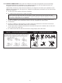
Figure 3 – Fall Clearance and Swing Falls
Figure 3A:
Clearance required in feet (meters) between Working Level and
Nearest Obstruction for User with Total Weight up to 310 lbs
(140 kg). Do not tie off below the harness Dorsal D-Ring.
7 ft
(2.1 m)
7 ft
(2.1 m)
9 ft
(2.7 m)
9 ft
(2.7 m)
11 ft
(3.4 m)
11 ft
(3.4 m)
5 ft
(1.5 m)
Clearance between
Working Level and
Nearest Obstruction
Figure 3B:
Swing Falls
Clearance between
Working Level and
Nearest Obstruction
To determine the clearance required: Measure the distance from the user’s harness dorsal connection to the
anchorage for the Rebel SRL. Both horizontal and vertical distances are required. Use Figure 3A above to determine the
required clearance between the working level and the nearest obstruction. The dotted lines in the gure represent 1 foot (0.3
m) increments from the user’s harness dorsal connection to the anchorage. For example, 7 ft (2.1 m) of clearance is required
when the Rebel unit is anchored 3 1/2 ft (1 m) above and 3 1/2 ft (1 m) to the side of the user’s harness dorsal connection.
NOTE: The clearances provided above assume the fall occurs from the standing position. If the worker is kneeling or
crouching an additional 3 ft (0.9 m) of clearance is needed.
2.15 COMPATIBILITY OF CONNECTORS: Connectors are considered to be compatible with connecting
elements when they have been designed to work together in such a way that their sizes and shapes do not
cause their gate mechanisms to inadvertently open regardless of how they become oriented. Contact Capital
Safety if you have any questions about compatibility.
Connectors (hooks, carabiners, and D-rings) must be capable of supporting at least 5,000 lbs. (22.2 kN).
Connectors must be compatible with the anchorage or other system components. Do not use equipment
that is not compatible. Non-compatible connectors may unintentionally disengage (see Figure 4). Connectors
must be compatible in size, shape, and strength. Self-locking snap hooks and carabiners are required by
ANSI Z359 and OSHA.

6
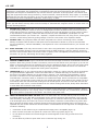
2.16 MAKING CONNECTIONS: Snap hooks and carabiners used with this equipment must be self-locking.
Ensure all connections are compatible in size, shape and strength. Do not use equipment that is not
compatible. Ensure all connectors are fully closed and locked.
Capital Safety connectors (snap hooks and carabiners) are designed to be used only as specied in each
product’s user’s instructions. See Figure 5 for examples of inappropriate connections. Do not connect snap
hooks and carabiners:
A. To a D-ring to which another connector is attached.
B. In a manner that would result in a load on the gate.
NOTE: Large throat snap hooks should not be connected to standard size D-rings or similar objects which will
result in a load on the gate if the hook or D-ring twists or rotates, unless the snap hook complies with ANSI
Z359.1-2007 or ANSI Z359.12 and is equipped with a 3,600 lb (16 kN) gate. Check the marking on your snap hook
to verify that it is appropriate for your application.
C. In a false engagement, where features that protrude from the snap hook or carabiner catch on the
anchor, and without visual conrmation seems to be fully engaged to the anchor point.
D. To each other.
E. Directly to webbing or rope lanyard or tie-back (unless the manufacturer’s instructions for both the
lanyard and connector specically allows such a connection).
F. To any object which is shaped or dimensioned such that the snap hook or carabiner will not close and
lock, or that roll-out could occur.
G. In a manner that does not allow the connector to align properly while under load.
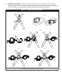
Figure 4 – Unintentional Disengagement Figure 5 – Inappropriate Connections
If the connecting element to which a snap hook (shown) or carabiner attaches
is undersized or irregular in shape, a situation could occur where the connecting
element applies a force to the gate of the snap hook or carabiner. This force may
cause the gate (of either a self-locking or a non-locking snap hook) to open,
allowing the snap hook or carabiner to disengage from the connecting point.
Small ring or other
non-compatibly
shaped element
Force is applied to the
Snap Hook.
The Gate presses against
the Connecting Ring.
The Gate opens allowing
the Snap Hook to slip off.
A. B. C. D.
E. F. G.

7
3.0 InstallatIon
3.1 PLANNING: Plan your fall protection
system before starting your work. Account
for all factors that may affect your safety
before, during, and after a fall. Consider
all requirements and limitations dened in
Section 2.
Important: In most applications,
the Rebel SRL can be connected to
the anchorage or the harness Dorsal
location. Either orientation is allowed.
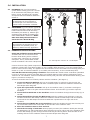
3.2 ANCHORAGE: Figure 6 illustrates typical SRL
anchorage connections. Select an anchorage
location with minimal free fall and swing
fall hazards (see Section 2). Select a rigid
anchorage point capable of sustaining the
static loads dened in Section 2.2. Rebel
SRLs must always be anchored at or
above the user’s Dorsal D-Ring.
Important: It is recommended that
this equipment be installed under the
supervision of a qualied person, as
dened by OSHA 1910.66, Appendix C.
3.3 HARNESS MOUNTING OPTIONS:
Single SRL Full Body Harness Mounting:
The Rebel SRL can be connected to the
harness dorsal D-Ring with a Carabiner
or Snap Hook. (See Figure 8, connection
examples 1 and 2). Some Rebel models
include a Carabiner. All include a Snap Hook.
Figure 6 – Anchorage Connections
A
B
A
B
C
A
B
A - Anchorage B - Connector C - Tie-Off Adapter
Connect the Swivel Eye (Rebel components identied in Figure 2) to the D-Ring on the harness using the
Carabiner included with some Rebel models (or use a suitably rated connector), or use the included Snap
Hook to connect to the D-Ring. The opposite end of the Rebel must be connected to an anchorage point (see
Section 2.3) with an included Carabiner (or a suitably rated connector), or the included Snap Hook.
Twin SRL Harness Mounting using a Carabiner: Some Rebel SRL models include a Carabiner (identied
in Figure 2) which can connect two Rebel SRLs to a Full Body Harness when climbing applications require
100% tie-off. The Carabiner mounts two Rebel SRLs side-by-side just below the harness Dorsal D-Ring. (See
Figure 8, connection example 3)
To mount two Rebel SRLs on a Full Body Harness with the Carabiner: (See Figure 7)
1. Loosen the Harness Webbing: Pull out on the Web Straps (A) where they pass through the
bottom of the Dorsal D-Ring (B) until there is sufcient space to slide the Carabiner between the
Web Straps and D-Ring Pad.
2. Open the Triple-Action Carabiner: Lift up on the Carabiner Gate (1) and twist it 45 degrees
(2) to align the slot in the gate with the Carabiner frame. Push the Gate (3) inward to open the
Carabiner.
3. Mount the rst Rebel SRL on the Carabiner: Insert the Carabiner through the Swivel Eye (C) on
the SRL.
4. Insert the Caribiner through the Web Straps: With the Carabiner Gate held open, insert the
Carabiner behind the Web Straps. Rotate the Carabiner behind the Web Straps until the Carabiner
surrounds the the Web Straps and the rst Rebel SRL is positioned on the right side of the
Carabiner.
5. Mount the second Rebel SRL on the Carabiner: Insert the Carabiner through the Swivel Eye on
the second SRL. Position the second SRL on the left side of the Carabiner Gate.
6. Allow the Carabiner Gate to close and lock.
7. Check the mounting of both SRLs: When properly mounted, the Carabiner should pass through
the Web Straps (A) and the SRL Swivel Eyes should be secured on either side of the Carabiner Gate.
Pull the Web Straps (A) back through the Dorsal D-Ring and D-Ring Pad to eliminate slack in the
webbing and secure the Carabiner between the Web Straps and D-Ring Pad.

8
4.0 UsE
WarnInG: Do not alter or intentionally misuse this equipment. Consult Capital Safety when using this
equipment in combination with components or subsystems other than those described in this manual. Some
subsystem and component combinations may interfere with the operation of this equipment. Use caution when
using this equipment around moving machinery, electrical hazards, chemical hazards, sharp edges, or overhead
materials that may fall onto the lifeline. Do not loop the lifeline around small structural members
. Failure to heed
this warning may result in equipment malfunction, serious injury, or death.
WarnInG: Consult your doctor if there is reason to doubt your tness to safely absorb the shock from a fall
arrest. Age and tness seriously affect a worker’s ability to withstand falls. Pregnant women or minors must not
use self retracting lifelines.
4.1 BEFORE EACH USE: Before each use of this fall protection equipment carefully inspect it to assure it is
in good working condition. Check for worn or damaged parts. Ensure all fasteners are present and secure.
Check that the lifeline is retracting properly by pulling out the line and allowing it to slowly retract. If there
is any hesitation in retraction, remove the SRL from service, mark “UNUSABLE”, and dispose of in the
recommended manner (see “Section 5.4 - Disposal”). Inspect the lifeline for cuts, frays, burns, crushing and
corrosion. Check locking action by pulling sharply on the line. See Section 5 for inspection details.
4.2 AFTER A FALL: Any equipment which has been subjected to the forces of arresting a fall or exhibits
damage consistent with the effect of fall arrest forces as described in Section 5, must be removed from
service immediately, marked “UNUSABLE”, and disposed of in the recommended manner (see “Section 5.4 -
Disposal”).
4.3 BODY SUPPORT: A full body harness must be worn when using Rebel SRLs. For general fall protection use,
connect to the back (dorsal) D-ring. For situations such as ladder climbing, it may be useful to connect to
the front of the harness above the worker’s center of gravity. This is acceptable provided potential free fall is
less than 2 ft. (61 cm) and footing can be easily regained.
Important: Do not use a body belt for free fall applications. See OSHA 1926.502 for guidelines.
4.4 MAKING CONNECTIONS: Figure 8 illustrates harness and anchorage connections for Rebel SRL Fall Arrest
Systems. When using a hook to make a connection, ensure roll-out cannot occur (see Figure 4). Do not use
hooks or connectors that will not completely close over the attachment object. Do not use non-locking snap
hooks. The anchorage must meet the anchorage strength requirements stated in section 2.3. Follow the
manufacturer’s instructions supplied with each system component.
4.5 OPERATION: Prior to use, inspect the SRL as described in section 5.0. Figure 8 shows system connections
for typical Rebel SRL applications. Connect the Rebel SRL to a suitable anchorage or mount the SRL on
the back of a Full Body Harness per the instruction in Section 3. On anchorage connected SRLs, connect
the Hook or Carabiner on the Load Indicator to the Dorsal D-Ring on the Full Body Harness. On harness
mounted SRLs, connect the Hook or Carabiner to a suitable anchorage. Ensure connections are compatible
in size, shape, and strength. Ensure hooks are fully closed and locked. Once attached, the worker is free to
move about within the recommended working area at normal speeds. If a fall occurs the SRL will lock and
arrest the fall. Upon rescue, remove the SRL from use. When working with an SRL, always allow the lifeline
to recoil back into the device under control.
WarnInG: Do not tie or knot the lifeline. Avoid lifeline contact with sharp or abrasive surfaces. Inspect
the lifeline frequently for cuts, fraying, burns, or signs of chemical damage. Dirt, contaminants, and water
can lower dielectric properties of the lifeline. Use caution near power lines.
4.6 TWIN LEG INTERFACE 100% TIE-OFF: When two Rebel SRLs are mounted side-by-side on the back of
a Full Body Harness, the SRL Fall Arrest System can be used for continuous fall protection (100 % tie-off)
while ascending, descending, or moving laterally (see Figure 9). With the Lifeline Leg of one SRL attached
to an anchorage point, the worker can move to a new location, attach the unused Lifeline Leg of the other
SRL to another anchorage point, and then disconnect from the original anchorage point. The sequence is
repeated until the worker reaches the desired location. Considerations for twin leg 100% tie-off applications
include the following:
• Connection of each Lifeline Leg to a separate anchorage point is acceptable (Figure 9).
• Never connect more than one person at a time to the Twin-Leg system (Figure 10).
• Do not allow the Lifelines to become tangled or twisted together as this may prevent them from
retracting.
• Do not allow any lifeline to pass under arms or between legs during use.

9
4.7 HORIZONTAL SYSTEMS: In applications where the Rebel SRL is used in conjunction with a horizontal
system (i.e. Horizontal Lifeline, Horizontal I-Beams Trolley), the SRL and horizontal system components
must be compatible. Horizontal systems must be designed and installed under the supervision of a qualied
engineer. Consult the horizontal system equipment manufacturer’s instructions for details.
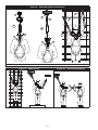
Figure 7 – Twin SRL Harness Connection
Step 1
A
B
Step 2
3
1
2
Step 3
C
Step 4
Step 5
Step 6
A - Web Straps B - Dorsal D-Ring C - Swivel Eye, SRL

10
Figure 8 – Rebel SRL System Connections
B
C
A
E
C
E
BA
C
B
C
A - Dorsal D-Ring B - Carabiner C - Snap Hook D - Rebar Hook E - Anchorage Point
Figure 9 – 100% Tie-Off Figure 10 – Incorrect Attachment
1
2
3

11
5.0 InspEctIon
5.1 INSPECTION FREQUENCY: The Rebel SRL must be inspected at the intervals dened in “Section 2.5 -
Inspection Frequency”. Inspection procedures are described in the “Inspection Checklist” (Table 2).
5.2 UNSAFE OR DEFECTIVE CONDITIONS: If inspection reveals an unsafe or defective condition, If
inspection reveals an unsafe condition, remove the SRL from service, mark “UNUSABLE”, and dispose of in
the recommended manner (see “Section 5.4 - Disposal”).
5.3 PRODUCT LIFE: The functional life of Rebel SRLs is determined by work conditions and maintenance. As
long as the SRL passes inspection criteria, it may remain in service.
5.4 DISPOSAL: Dispose of the Rebel SRL if it has been subjected to fall force or inspection reveals an unsafe or
defective condition. Before disposing of the SRL, cut the Load Indicator off of the Web Lifeline or otherwise
disable the SRL to eliminate the possibility of inadvertent reuse.
6.0 maIntEnancE, sErVIcInG, and storaGE
6.1 CLEANING: Cleaning procedures for the Rebel SRL are as follows:
• Periodically clean the exterior of the SRL using water and a mild soap solution. Position the SRL so
excess water can drain out. Clean labels as required.
• Clean the Web Lifeline with water and mild soap solution. Rinse and thoroughly air dry. Do not force dry
with heat. The lifeline should be dry before allowing it to retract into the housing. An excessive buildup
of dirt, paint, etc. may prevent the lifeline from fully retracting back into the housing causing a potential
free fall hazard.
Important: If the lifeline contacts acids or other caustic chemicals, remove the SRL from service
and wash with water and a mild soap solution. Inspect the SRL per Table 2 before returning to
service.
6.2 SERVICE: Rebel SRLs are not repairable. If the SRL has been subjected to fall force or inspection reveals
an unsafe or defective condition, remove the SRL from service, mark “UNUSABLE”, and dispose of in the
recommended manner (see “Section 5.4 - Disposal”).
6.3 STORAGE: Store Rebel SRLs in a cool, dry, clean environment out of direct sunlight. Avoid areas where
chemical vapors may exist. Thoroughly inspect the SRL after any period of extended storage.
7.0 spEcIFIcatIons
7.1 PERFORMANCE: Your Rebel SRL has been tested and certied to the performance requirements of
the standard(s) identied on the cover of this instruction manual. See “Section 2.0 - Limitations &
Requirements” for performance specications.
7.2 MATERIALS: Material specications for the Rebel SRL are as follows:
Housing: Nylon, UV Resistant Motor Spring: Stainless Steel
Drum: Nylon, Type 6/6 Swivel: Zinc Plated Steel
Fasteners: Zinc Plated Steel Screws; Stainless
Steel Rivets
Lifeline: Polyester Web
Locking Pawls: Stainless Steel Load Indicator Cover: PVC Tubing
Web: Polyester
Main Shaft: Stainless Steel
End
Connectors:
(See Figure 1)
Gate Opening Gate Strength
Steel Carabiner 3/4 in (19 mm) 3,600 lb (16 kN)
Steel Snap Hook 3/4 in (19 mm) 3,600 lb (16 kN)
Steel Swiveling Snap Hook 3/4 in (19 mm) 3,600 lb (16 kN)
Steel Rebar Hook 2 1/4 in (57 mm) 3,600 lb (16 kN)
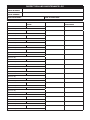
7.3 LABELING: Figure 14 illustrates Rebel SRL labeling. All labels on the SRL must be present and fully legible.

12
Table 2 – Inspection Checklist
Component: Inspection: Pass Fail
SRL
(Figure 11)
Inspect for loose fasteners and bent or damaged parts.
Inspect the Housing (A) for distortion, cracks, or other damage.
Inspect the Swivel (B) and Swivel Eye (C) and Carabiner (D) for distortion,
cracks, or other damage. The Swivel should be attached securely to the SRL,
but should pivot freely. The Swivel Eye or Integral Connector should rotate
freely in the Swivel.
The Web Lifeline (E) should pull out and retract fully without hesitation or
creating a slack line condition.
Ensure the SRL locks up when the Lifeline is jerked sharply. Lockup should be
positive with no slipping.
All labels must be present and fully legible (see Figure 14).
Inspect the entire SRL for signs of corrosion.
Web Lifeline
(Figure 12)
Inspect the web lifeline for concentrated wear, frayed strands, broken yarn,
burns, cuts, and abrasions. The lifeline must be free of knots throughout its
length. Inspect for excessive soiling, paint build-up, and rust staining. Inspect
for chemical or heat damage indicated by brown, discolored, or brittle areas.
Inspect for ultraviolet damage indicated by discoloration and the presence of
splinters and slivers on the lifeline surface.
Load Indicator
(Figure 13)
Inspect the Load Indicator to determine if it has been activated. There should
be no evidence of elongation and the cover should be secure and free of tears
or other damage.
End Connectors
(Figure 1)
Figure 1 identies the End Connectors that should be included on your Rebel
SRL model. Inspect Snap Hooks, Carabiner, Rebar Hooks, etc. for signs of
damage, corrosion, and proper working condition. Where present: Swivels
should rotate freely, and Carabiner and Hook Gates should open, close, lock,
and unlock properly.
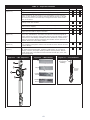
Figure 11 – SRL Inspection
B
D
A
C
E
Figure 12 – Web Lifeline
Cut
Frayed
Heavily
Soiled
Welding
Burns
Figure 13 – Load Indicator
Torn or
Broken
Cover
Deployed and
Torn/Frayed
Webbing

13
Figure 14 – Labeling
D

INSPECTION AND MAINTENANCE LOG
SERIAL NUMBER:
MODEL NUMBER:
DATE PURCHASED: DATE OF FIRST USE:
INSPECTION DATE INSPECTION ITEMS
NOTED
CORRECTIVE ACTION MAINTENANCE
PERFORMED
Approved By:
Approved By:
Approved By:
Approved By:
Approved By:
Approved By:
Approved By:
Approved By:
Approved By:
Approved By:
Approved By:
Approved By:
Approved By:
Approved By:
Approved By:
Approved By:
Approved By:
Approved By:

LIMITED LIFETIME WARRANTY
Warranty to End User: D B Industries, Inc., dba CAPITAL SAFETY USA (“CAPITAL SAFETY”)
warrants to the original end user (“End User”) that its products are free from defects in materials and
workmanship under normal use and service. This warranty extends for the lifetime of the product
from the date the product is purchased by the End User, in new and unused condition, from a CAPITAL
SAFETY authorized distributor. CAPITAL SAFETY’S entire liability to End User and End User’s exclusive
remedy under this warranty is limited to the repair or replacement in kind of any defective product
within its lifetime (as CAPITAL SAFETY in its sole discretion determines and deems appropriate). No oral
or written information or advice given by CAPITAL SAFETY, its distributors, directors, offi cers, agents
or employees shall create any different or additional warranties or in any way increase the scope of
this warranty. CAPITAL SAFETY will not accept liability for defects that are the result of product abuse,
misuse, alteration or modifi cation, or for defects that are due to a failure to install, maintain, or use the
product in accordance with the manufacturer’s instructions.
CAPITAL SAFETY’S WARRANTY APPLIES ONLY TO THE END USER. THIS WARRANTY IS THE ONLY
WARRANTY APPLICABLE TO OUR PRODUCTS AND IS IN LIEU OF ALL OTHER WARRANTIES AND
LIABILITIES, EXPRESSED OR IMPLIED. CAPITAL SAFETY EXPRESSLY EXCLUDES AND DISCLAIMS
ANY IMPLIED WARRANTIES OF MERCHANTABILITY OR FITNESS FOR A PARTICULAR PURPOSE, AND
SHALL NOT BE LIABLE FOR INCIDENTAL, PUNITIVE OR CONSEQUENTIAL DAMAGES OF ANY NATURE,
INCLUDING WITHOUT LIMITATION, LOST PROFITS, REVENUES, OR PRODUCTIVITY, OR FOR BODILY
INJURY OR DEATH OR LOSS OR DAMAGE TO PROPERTY, UNDER ANY THEORY OF LIABILITY, INCLUDING
WITHOUT LIMITATION, CONTRACT, WARRANTY, STRICT LIABILITY, TORT (INCLUDING NEGLIGENCE) OR
OTHER LEGAL OR EQUITABLE THEORY.
GARANTIE LIMITÉE SUR LA DURÉE DE VIE
Garantie offerte à l’utilisateur fi nal : D B Industries, Inc., dba CAPITAL SAFETY USA (« CAPITAL SAFETY »)
garantit à l’utilisateur fi nal d’origine (« Utilisateur fi nal ») que les produits sont libres de tout défaut matériel et de
fabrication dans des conditions normales d’utilisation et de service. Cette garantie couvre toute la durée de vie du
produit, de sa date d’achat à l’état neuf et inutilisé par l’utilisateur auprès d’un distributeur agréé CAPITAL SAFETY.
La responsabilité intégrale de Capital Safety et le seul recours du Client dans le cadre de cette garantie se limitent
à la réparation ou le remplacement en nature des produits défectueux pendant leur durée de vie (à la seule
discrétion de Capital Safety et selon ce qu’elle juge approprié). Aucun renseignement ou avis oral ou écrit fourni par
CAPITAL SAFETY, ses détaillants, administrateurs, cadres, distributeurs, mandataires ou employés ne représentera
une garantie ou n’augmentera de quelque manière la portée de la présente garantie limitée. CAPITAL SAFETY
n’accepte aucune responsabilité pour les défauts causés par un abus, une utilisation abusive, une altération ou une
modifi cation, ou pour les défauts causés par le non-respect des instructions du fabricant relatives à l’installation,
à l’entretien ou à l’utilisation du produit.
CETTE GARANTIE CAPITAL SAFETY S’APPLIQUE UNIQUEMENT À L’UTILISATEUR FINAL. ELLE EST LA SEULE
GARANTIE APPLICABLE À NOS PRODUITS. ELLE EXCLUT TOUTE AUTRE GARANTIE EXPRESSE OU IMPLICITE.
CAPITAL SAFETY EXCLUT EXPLICITEMENT ET DÉCLINE TOUTE GARANTIE IMPLICITE DE MISE EN MARCHÉ ET
D’ADAPTATION À DES FINS PARTICULIÈRES, ET NE SERA RESPONSABLE POUR AUCUN DOMMAGE-INTÉRÊT
DIRECT OU INDIRECT, CORRÉLATIF OU ACCESSOIRE DE TOUTE NATURE Y COMPRIS ET DE MANIÈRE NON
LIMITATIVE, LES PERTES DE PROFITS, LES REVENUS OU LA PRODUCTIVITÉ, LES BLESSURES CORPORELLES,
VOIRE LA MORT OU DOMMAGES À LA PROPRIÉTÉ, DANS LE CADRE DE TOUTE THÉORIE DE RESPONSABILITÉ, Y
COMPRIS ET DE MANIÈRE NON LIMITATIVE UN CONTRAT, UNE GARANTIE, UNE RESPONSABILITÉ (Y COMPRIS LA
NÉGLIGENCE) OU TOUTE AUTRE THÉORIE LÉGALE OU ÉQUITABLE.
GARANTÍA LIMITADA DE POR VIDA
Garantía para el usuario fi nal: D B Industries, Inc., que opera bajo el nombre de CAPITAL SAFETY USA
(“CAPITAL SAFETY”) garantiza al usuario fi nal original (“Usuario fi nal”) que sus productos están libres de defectos
de materiales y de mano de obra en condiciones normales de uso y mantenimiento. Esta garantía se extiende
durante la vida útil del producto a partir de la fecha en que el Usuario fi nal adquiere el producto, nuevo y sin
uso, a un distribuidor autorizado de CAPITAL SAFETY. La entera responsabilidad de CAPITAL SAFETY hacia el
Usuario fi nal y el remedio exclusivo para el Usuario fi nal bajo esta garantía están limitados a la reparación o el
reemplazo por materiales de todo producto defectuoso dentro de su vida útil (según CAPITAL SAFETY lo determine
y considere apropiado a su solo criterio). Ninguna información o asesoramiento, oral o escrito, proporcionado
por CAPITAL SAFETY, sus distribuidores, directores, funcionarios, agentes o empleados creará una garantía
diferente o adicional ni aumentará de ninguna manera el alcance de esta garantía. CAPITAL SAFETY no aceptará
responsabilidad por defectos resultantes del abuso, el uso incorrecto, la alteración o la modifi cación del producto,
ni por defectos resultantes de no respetar las instrucciones del fabricante durante la instalación, el mantenimiento
o el uso del producto.
LA GARANTÍA DE CAPITAL SAFETY SE APLICA ÚNICAMENTE AL USUARIO FINAL. ESTA GARANTÍA ES LA
ÚNICA GARANTÍA QUE SE APLICA A NUESTROS PRODUCTOS Y REEMPLAZA A TODAS LAS OTRAS GARANTÍAS
Y RESPONSABILIDADES, EXPRESAS O IMPLÍCITAS. CAPITAL SAFETY EXPRESAMENTE EXCLUYE Y RENUNCIA A
TODAS LAS GARANTÍAS IMPLÍCITAS DE COMERCIABILIDAD O APTITUD PARA UN PROPÓSITO PARTICULAR, Y
NO SERÁ RESPONSABLE POR DAÑOS INCIDENTALES, PUNITIVOS O EMERGENTES DE NINGUNA NATURALEZA,
INCLUYENDO SIN LIMITACIÓN PÉRDIDAS DE INGRESOS, GANANCIAS O PRODUCTIVIDAD; NI POR
LESIONES CORPORALES O MUERTE, O PÉRDIDA DE O DAÑO A LA PROPIEDAD, BAJO CUALQUIER TEORÍA DE
RESPONSABILIDAD, INCLUYENDO SIN LIMITACIÓN CONTRATO, GARANTÍA, RESPONSABILIDAD ESTRICTA,
AGRAVIO (INCLUIDA NEGLIGENCIA) O CUALQUIER OTRA TEORÍA LEGAL O EQUITATIVA.

Trusted Quality Fall Protection
ISO
9001
CSG USA & Latin America
3833 SALA Way
Red Wing, MN 55066-5005
Toll Free: 800.328.6146
Phone: 651.388.8282
Fax: 651.388.5065
solutions@capitalsafety.com
CSG Canada
260 Export Boulevard
Mississauga, ON L5S 1Y9
Phone: 905.795.9333
Toll-Free: 800.387.7484
Fax: 888.387.7484
info.ca@capitalsafety.com
CSG Northern Europe
5a Merse Road
North Moons, Moat
Reditch, Worcestershire, UK
B98 9HL
Phone: + 44 (0)1527 548 000
Fax: + 44 (0)1527 591 000
csgne@capitalsafety.com
CSG EMEA
(Europe, Middle East, Africa)
Le Broc Center
Z.I. 1ère Avenue
5600 M B.P. 15 06511
Carros
Le Broc Cedex
France
Phone: + 33 4 97 10 00 10
Fax: + 33 4 93 08 79 70
information@capitalsafety.com
CSG Australia & New Zealand
95 Derby Street
Silverwater
Sydney NSW 2128
AUSTRALIA
Phone: +(61) 2 8753 7600
Toll-Free : 1 800 245 002 (AUS)
Toll-Free : 0800 212 505 (NZ)
Fax: +(61) 2 8753 7603
sales@capitalsafety.com.au
CSG Asia
Singapore:
16S, Enterprise Road
Singapore 627666
Phone: +65 - 65587758
Fax: +65 - 65587058
inquiry@capitalsafety.com
Shanghai:
Rm 1406, China Venturetech Plaza
819 Nan Jing Xi Rd,
Shanghai 200041, P R China
Phone: +86 21 62539050
Fax: +86 21 62539060
www.capitalsafety.com
-
 1
1
-
 2
2
-
 3
3
-
 4
4
-
 5
5
-
 6
6
-
 7
7
-
 8
8
-
 9
9
-
 10
10
-
 11
11
-
 12
12
-
 13
13
-
 14
14
-
 15
15
-
 16
16


3M PROTECTA® Twin-Leg Self Retracting Lifeline Web 3100412, Red, 6 ft. (1.8 m), 1 ea Mode d'emploi
- Taper
- Mode d'emploi
- Ce manuel convient également à
-
- PROTECTA® Rebel™ Self Retracting Lifeline - Web 3100403, Red, 6 ft. (1.8 m)
- PROTECTA® Rebel™ Self Retracting Lifeline, Web 3100400, Red, 6 ft. (1.8 m)
- Protecta® Retracting Lifeline 3100414, Web, Twin legs, Thermoplastic Housing, Rebar Hooks, 6ft (1.8m)
- PROTECTA® Self Retracting Lifeline - Web 3100401, Red, 6 ft. (1.8 m), 1 EA/Case
- PROTECTA® Self Retracting Lifeline - Web 3100402, Red, 6 ft. (1.8 m), 1 EA
- PROTECTA® Self Retracting Lifeline - Web 3100404, Red, 6 ft. (1.8 m), 1 EA
- Protecta® Self Retracting Lifeline 3100405, Web, Thermoplastic Housing, Steel Rebar Hook, 6ft (1.8m)
- PROTECTA® Twin-Leg Self Retracting Lifeline - Web 3100413, Red, 6 ft. (1.8 m), 1 EA
dans d''autres langues
Documents connexes
-
3M PROTECTA® Self Retracting Lifeline - Web 3100433, Red, 20 ft. (6.1 m), 1 EA Mode d'emploi
-
3M 3102003 Manuel utilisateur
-
-
-
-
-
-
-
-
Autres documents
-
Honeywell Miller MightEvac User Instruction Manual
-
DeWalt D1000 Series Manuel utilisateur
-
-
 Workman Self-Retracting Lanyard Le manuel du propriétaire
-
Guardian Xplorer Harness Mode d'emploi
-
-
 FireHawk Rescue Belt II Le manuel du propriétaire
-

