GE IM4LED Le manuel du propriétaire
- Catégorie
- Frigos
- Taper
- Le manuel du propriétaire
Ce manuel convient également à

SAFETY INFORMATION .........3
USING THE ICEMAKER
Automatic Icemaker ....................4
Preparing for Vacation .................4
Setting the icemaker to OFF ............4
Normal sounds you may hear. . . . . . . . . . . .4
INSTALLATION
INSTRUCTIONS .................5
Icemaker Installation U, V, W or X .......7
Icemaker Installation T (IM4D only) .....10
Water Valve Assembly
Installation U, V, W or X .............12
Water Valve Assembly
Installation T (IM4D only) ............14
Water Line Installation ................16
TROUBLESHOOTING ........... 20
LIMITED WARRANTY .............23
CONSUMER SUPPORT ......... 24
ENGLISH/FRANÇAIS/
ESPAÑOL
245D1524P001 49-60698 Rev. 7 07-19 GEA
OWNER’S MANUAL &
INSTALLATION
INSTRUCTIONS
ICEMAKER ACCESSORY KIT
IM4D and IM4LED
GE is a trademark of the General Electric Company. Manufactured under trademark license.

2 49-60698 Rev. 7
THANK YOU FOR MAKING GE APPLIANCES A PART OF YOUR HOME.
Whether you grew up with GE Appliances, or this is your first, we’re happy to have you in the family.
We take pride in the craftsmanship, innovation and design that goes into every
GE Appliances product, and we think you will too.

49-60698 Rev. 7 3
WARNING
To reduce the risk of fire, explosion, electric shock, or injury when using your
refrigerator, follow these basic safety precautions:
Ŷ5HDGWKHIXOO6DIHW\,QIRUPDWLRQDQG,QVWUXFWLRQV
of your refrigerator before installing or operating
the icemaker.
Ŷ8QSOXJWKHUHIULJHUDWRUEHIRUHEHJLQQLQJWKH
installation of this icemaker accessory kit.
Ŷ:KHQPRYLQJWKHUHIULJHUDWRUDZD\IURPWKH
wall, be careful not to roll over or damage the
power cord.
Ŷ5HSODFHDOOSDUWVDQGSDQHOVRIWKHUHIULJHUDWRU
before operating.
Ŷ&RQQHFWWRSRWDEOHZDWHUVXSSO\RQO\
CAUTION
Avoid contact with the moving parts of the icemaker ejector mechanism, or with the heating element
that releases the cubes, located on the bottom of the icemaker. Do not place fingers or hands on the
automatic icemaker while the refrigerator is plugged in.
SAFETY INFORMATION
READ AND SAVE THESE INSTRUCTIONS
IMPORTANT SAFETY INFORMATION
READ ALL INSTRUCTIONS BEFORE INSTALLING THE
ICEMAKER OR ACCESSORIES

4 49-60698 Rev. 7
The icemaker will produce seven cubes per cycle-
approximately 100-130 cubes in a 24-hour period,
depending on freezer compartment temperature, room
temperature, number of door openings and other use
conditions.
,IWKHUHIULJHUDWRULVRSHUDWHGEHIRUHWKHZDWHUFRQQHFWLRQ
is made to the icemaker, set the power switch to OFF.
When the refrigerator has been connected to the water
supply, set the power switch to ON.
The icemaker will fill with water when it cools to freezing.
A newly-installed refrigerator may take 12 to 24 hours to
begin making ice cubes.
You will hear a buzzing sound each time the icemaker
fills with water.
Throw away the first few batches of ice to allow the
water line to clear.
Be sure nothing interferes with the sweep of the feeler
arm.
When the bin fills to the level of the feeler arm, the
icemaker will stop producing ice.
,WLVQRUPDOIRUVHYHUDOFXEHVWREHMRLQHGWRJHWKHU
,ILFHLVQRWXVHGIUHTXHQWO\ROGLFHFXEHVZLOOEHFRPH
cloudy, taste stale and shrink.
IM4LED only:
7KLVLFHPDNHULVHTXLSSHGZLWK/('OLJKWVWKDWDUH
activated by a motion sensor when the freezer door is
opened.
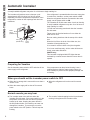
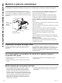
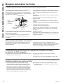
Automatic Icemaker
USING THE ICEMAKER
A newly-installed refrigerator may take 12 to 24 hours to begin making ice.
,FHPDNHU
Feeler Arm
Power
6ZLWFK
Preparing for Vacation
6HWWKHLFHPDNHUSRZHUVZLWFKWR2))DQGVKXWRIIWKH
water supply to the refrigerator.
,IWKHWHPSHUDWXUHFDQGURSEHORZIUHH]LQJKDYHD
TXDOLILHGVHUYLFHUGUDLQWKHZDWHUVXSSO\V\VWHPRQ
some models) to prevent serious property damage due
to flooding.
When you should set the icemaker power switch to OFF
Ŷ:KHQWKHLFHVWRUDJHELQLVUHPRYHGIRUPRUHWKDQD
minute or two.
Ŷ:KHQWKHZDWHUVXSSO\ZLOOEHVKXWRIIIRUVHYHUDO
hours.
Ŷ:KHQWKHUHIULJHUDWRUZLOOQRWEHXVHGIRUVHYHUDO
days.
Normal sounds you may hear
Ŷ7KHLFHPDNHUZDWHUYDOYHZLOOEX]]ZKHQWKH
LFHPDNHUILOOVZLWKZDWHU,IWKHSRZHUVZLWFKLVLQWKH
21SRVLWLRQLWZLOOEX]]HYHQLILWKDVQRW\HWEHHQ
hooked up to water. Keeping the power switch in
WKH21SRVLWLRQEHIRUHLWLVKRRNHGXSWRZDWHUFDQ
damage the icemaker. To prevent this, move the
SRZHUVZLWFKWRWKH2))SRVLWLRQ7KLVZLOOVWRSWKH
buzzing.
Ŷ7KHVRXQGRIFXEHVGURSSLQJLQWRWKHELQDQGZDWHU
running in the pipes as the icemaker refills.
/('/LJKW
,0/('2QO\
0RWLRQ
6HQVRU
,0/('2QO\

49-60698 Rev. 7 5
BEFORE YOU BEGIN
Read these instructions completely and carefully.
• IMPORTANT – 6DYHWKHVHLQVWUXFWLRQVIRU
local inspector’s use.
• IMPORTANT – 2EVHUYHDOOJRYHUQLQJFRGHV
and ordinances.
• Note to Installer – Be sure to leave these
LQVWUXFWLRQVZLWKWKH&RQVXPHU
• Note to Consumer – Keep these instructions
for future reference.
• Skill level±,QVWDOODWLRQRIWKLVDSSOLDQFHUHTXLUHV
basic mechanical skills.
• Completion time – 20–60 minutes
• Proper installation is the responsibility of the
installer.
• Product failure due to improper installation is not
covered under the Warranty.
,I\RXKDYHTXHVWLRQVFDOO*($SSOLDQFHVDW1.800.GE.CARES or visit our Website at:
GEAppliances.com.,Q&DQDGDFDOO1.800.561.3344 or visit our Website at: geappliances.ca
Installation
Instructions
IM4D and IM4LED
Icemaker Kit
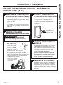
ARE YOU REPLACING AN
ICEMAKER WITH THIS KIT?
,W¶VLPSRUWDQWWKDW\RXXVHWKHZDWHUYDOYHDQGILOO
tube assembly that come with this kit, even though
your refrigerator may already have them installed.
The old valve will not allow enough water through to
fill the icemaker properly and will cause damage.
Damage – Shipment/Installation
Ɣ,IWKHXQLWLVGDPDJHGLQVKLSPHQWUHWXUQWKHXQLW
to the store in which it was bought for repair or
replacement.
Ɣ,IWKHXQLWLVGDPDJHGE\WKHFXVWRPHUUHSDLURU
replacement is the responsibility of the customer.
Ɣ,IWKHXQLWLVGDPDJHGE\WKHLQVWDOOHULIRWKHUWKDQ
the customer), repair or replacement must be made
by arrangement between customer and installer.
INSTALLATION INSTRUCTIONS

6 49-60698 Rev. 7
Installation Instructions
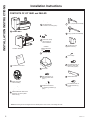
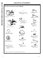
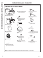
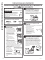
CONTENTS OF KIT IM4D and IM4LED
,QVWDOODWLRQ,QVWUXFWLRQV
2
+H[+HDG6FUHZ
IRU:DWHU/LQH&ODPS´
5
Water Valve and
Tube Assembly
3
Adhesive-Backed Water Tube
Fasteners, to secure plastic
ZDWHUWXEH
4
+H[+HDG6FUHZIRU
attaching water valve
´
9
,FH%XFNHW
8
:DWHU/LQH&ODPS
VWUDLQUHOLHIIRU
house water line
6
11
12
6KRUW~´)LOOWXEH$VVHPEO\
/RQJ~´)LOOWXEH$VVHPEO\
10
3KLOOLSV+HDG6FUHZV
IRUPRXQWLQJLFHPDNHU
´
:DUUDQW\/DEHO
ICEMAKER
WARRANTY VERIFICATION
Date Installed
Dealer
13
14
15
16
,FHPDNHU)LOO&XS
VLGHPRXQWHG
,FHPDNHU,0'
1
,QVWDOODWLRQ
,QVWUXFWLRQV
+RVH&ODPS
+H[+HDG6FUHZVIRU
attaching water tube
LQOHWFRYHU´
+H[+HDG6FUHZVIRU
EUDFNHWH[WHQVLRQ
´
Bracket Extension
NOTE6FUHZOHQJWKVDUHWKHOHQJWKVRIWKHWKUHDGHGSRUWLRQRIWKHVFUHZQRWLQFOXGLQJWKHKHDG
INSTALLATION INSTRUCTIONS
,FHPDNHU,0'RU
,FHPDNHU,0/('

49-60698 Rev. 7
INSTALLATION INSTRUCTIONS
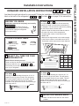
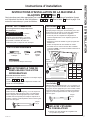
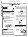
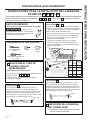
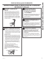
1
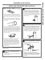
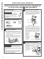
SELECT FILL TUBE FOR YOUR
REFRIGERATOR
Which fill tube should you use?
There is a label on the back of the refrigerator that
will tell you which to use:
8
V
W
or
X
The fill tube you use will depend on the model and
size of your refrigerator.
For letter
U
8VHORQJILOOWXEHDVVHPEO\DQGFXWRII´RI
length from the tip of the fill tube. This will ensure
the correct length fill tube for your model. This will
provide proper water flow into your fill cup and
LFHPDNHU,WZLOOSUHYHQWWKHILOOWXEHIURPIUHH]LQJXS
with water and ice.
For letter
W
8VHVKRUWILOOWXEHDVVHPEO\DQGFXWRII´RI
length from the tip of the fill tube. This will ensure
the correct length fill tube for your model. This will
provide proper water flow into your fill cup and
LFHPDNHU,WZLOOSUHYHQWWKHILOOWXEHIURPIUHH]LQJXS
with water and ice.
For letter
V
and
X
,WLVLPSRUWDQWWRXVHWKHFRUUHFWILOOWXEHDVVHPEO\
because the length is critical to the performance of
\RXULFHPDNHU,WLVDOVRFULWLFDOWRSUHYHQWDQ\OHDNLQJ
from the fill tube into the freezer itself.
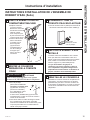
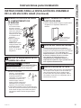
2SHQWKHIUHVKIRRGGRRUDQGORFDWHWKHODEHOLQ
the upper left corner of the compartment.
• Find the model number in bold listed under
02'(/12
0DWFKWKHWZRGLJLWQXPEHULQWKHPRGHOQXPEHU
WRWKHILOOWXEHQXPEHULQWKHWDEOHEHORZ127(
The desired number starts at the fourth character.
Installation Instructions
ICEMAKER INSTALLATION INSTRUCTIONS
U
V
W
OR
X
Flat blade and Phillips
screwdrivers
Pliers
6KDUSNQLIH
&XW´&XW´
&XW´
$UHWKHVHWKHULJKWLQVWUXFWLRQVIRU\RXUPRGHO")ROORZWKH,QVWDOODWLRQ,QVWUXFWLRQVLQGLFDWHGE\WKH
label on the back of the refrigerator -
8
V
W
or
X
. For letter
T
, go to page 10 for instructions.
BEFORE YOU BEGIN
Read these instructions completely and carefully.
WARNING
To reduce the risk of
electric shock or injury during installation,
you must first unplug the refrigerator
before proceeding.
2
REPOSITION FREEZER SHELF
Ɣ0DNHVXUHWKHIUHH]HUVKHOILVLQWKHORZHVW
position.
TOOLS YOU WILL NEED
GENERAL ELECTRIC COMPANY
APPLIANCE PARK LOUISVILLE, KY 40225
www.GEAppliances.com
LISTED HOSEHOLD REFRIGERATOR/FREEZER
SERIAL NO.
182A
MODEL NO.
FZ743041GTH18GBDCRWW
IIIIIIIIIIIIIIIIIIIIIIIIIIIIIIIIIIIIIIIIIIIIIIIIIIIIIIIIIIIIIIIIIIIIII
IIIIIIIIIIIIIIIIIIIIIIIIIIIIIIIIIIIIIIIIIIIIIIIIIIIIIIIIIIIIIIIIIIIIIIIIIIIIII
IIIIIIIIIIIIIIIIIIIIIIIIIIIIIIIIIIIIIIIIIIIIIIIIIIIIIIIIIIIIIIIIIIIIIIII
IIIIIIIIIIIIIIIIIIIIIIIIIIIIIIIIIIIIIIIIIIIIIIIIIIIIIIIIIIIIIIIIIIIIIIII
IIIIIIIIIIIIIIIIIIIIIIIIIIIIIIIIIIIIIIIIIIIIIIIIIIIIIIIIIIIIIII
IIIIIIIIIII
IIIIIIII
IIIIII
/HWWHU
0RGHO
1XPEHU
Fill
Tube
V 15, 16, 11
V
12, 18,
21
12
X
18
12
X 19, 22 11
0RGHO1XPEHU
DQG1XWGULYHUV

8 49-60698 Rev. 7
Installation Instructions
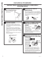
ICEMAKER INSTALLATION INSTRUCTIONS (Continued)
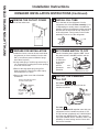
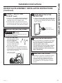
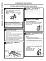
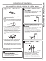
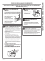
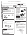
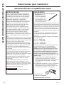
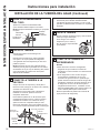
3
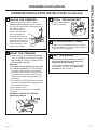
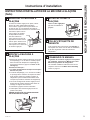
REMOVE THE OUTLET COVER
Peel off the outlet cover.
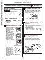
6
SET POWER SWITCH TO OFF
6HWWKHLFHPDNHUSRZHUVZLWFKWROFF/HDYH
the power switch in the OFF position until the
refrigerator
is connected
to the water
supply to
prevent
premature
operation.
INSTALL THE ICEMAKER
FILL CUP
For letters
U
,
V
&
X
,QVWDOOWKHicemaker fill cupLQWRWKH
icemaker as shown.
For letter
W
,QVWDOOWKHicemaker fill cup that came with your
UHIULJHUDWRULQWRWKHLFHPDNHUDVVKRZQ,IWKH
fill cup has been misplaced, call 1.800.626.2002
DQGRUGHUSDUW:5;,IWKHFRUUHFWILOO
cup is not installed into the icemaker, there is the
possibility of water leaking into the freezer and
not into the icemaker.
5
INSTALL FILL TUBE
*RWRWKHEDFNRIWKHUHIULJHUDWRU2QWKH
refrigerator side of the fill tube assembly RU
12 depending on model), there is an adhesive
EDFNLQJ5HPRYHWKHDGKHVLYHEDFNLQJDQGVOLGH
the tube into the hole near the top at the back
of the refrigerator. Firmly press on the fill tube
assembly to secure it to the refrigerator.
REMOVE ONLY
TO INSTALL
WATER FILL TUBE
11 12
or
Power
6ZLWFK
$SSHDUDQFHPD\YDU\
13
$SSHDUDQFH
may vary)
INSTALLATION INSTRUCTIONS
4
PREPARE FOR INSTALLATION
Ɣ ,QVLGHWKHIUHH]HUUHPRYHWKHWZRVPDOOZKLWH
SOXJEXWWRQVRQVRPHPRGHOVIURPWKHVLGH
ZDOO,IVFUHZVDUHSUHVHQWLQVWHDGRISOXJV
leave them in place.)
Ɣ$ODUJHZKLWHSOXJRUDZKLWHFDSVHFXUHGE\D
VFUHZZLOOEHFRYHULQJWKHILOOWXEHRSHQLQJ
in the rear freezer wall.
Ɣ5HPRYHWKHODUJHZKLWHSOXJXVLQJDIODW
EODGHVFUHZGULYHU5HPRYHWKHZKLWHFDSE\
XQVFUHZLQJWKHVFUHZ
Ɣ5HPRYHWKHRXWOHWFRYHUZLWKDIODWEODGH
screwdriver.
2XWOHW
cover
5HPRYHVLGHZDOOSOXJEXWWRQV
or leave screws in place
5HDUZDOO
plug button
RQVRPH
models)

49-60698 Rev. 7 9
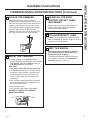
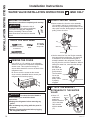
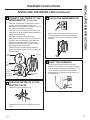
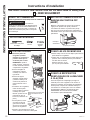
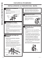
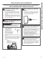
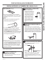
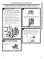
8
PLUG IN THE ICEMAKER
Holding the icemaker in place, insert the
icemaker power cord plug into the socket on
the side wall, making sure the prongs and holes
are matched. Press
the plug firmly into the
VRFNHW/RFNWKHSOXJLQ
place by clipping the
restraints onto each side
RIWKHSOXJ0DNHVXUHWKH
restraints click into place.
0DNHVXUHWKHSRZHUFRUG
is still in the hook on the
back of the icemaker.
INSTALLATION INSTRUCTIONS
Hook
Installation Instructions
ICEMAKER INSTALLATION INSTRUCTIONS (Continued)
9
MOUNT THE ICEMAKER
Ɣ/LIWWKHLFHPDNHUVRWKH fill tube assembly
RUGHSHQGLQJRQPRGHOILWVLQWKHfill
cup opening'+DQJWKHLFHPDNHURQWKH
two mounting screws%
Make sure:
Ɣ The power cord is still firmly in the socket.
Ɣ7KHfill tube assemblyRUGHSHQGLQJ
on model) extends into the fill cup opening
DWWKHEDFNRIWKHLFHPDNHU&KHFNWKHUHDU
of the refrigerator to make sure the fill tube
has not been pushed out of the back of the
refrigerator).
Ɣ7KHLFHPDNHUPRXQWLQJVFUHZVDUHORFDWHGLQ
the uppermost position of the mounting slots
on the icemaker bracket.
Ɣ7KHLFHPDNHULVOHYHO
Ɣ7KHLFHPDNHUSRZHUVZLWFKLVLQWKHOFF
position.
SECURELY TIGHTEN THE ICEMAKER
MOUNTING SCREWS.
11 12
D
B
10
INSTALL THE ICE BUCKET
Place the ice bucket
under the icemaker.
11
ATTACH WARRANTY LABEL
A labelLVSURYLGHGZLWKWKLVNLWWRUHFRUGWKH
date of installation for warranty purposes. Apply it
to the back of the refrigerator.
12
KEEP THIS MANUAL
The warranty for the icemaker is printed in
this manual. Keep this manual with your
Refrigerator Owner’s Manual.
The icemaker installation inside the freezer is
QRZFRPSOHWH&RQWLQXHWRWKHWater Valve
Assembly section on page 12.
8

10 49-60698 Rev. 7
Installation Instructions
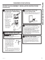
2
SET POWER SWITCH TO OFF
6HWWKHLFHPDNHUSRZHUVZLWFKWROFF/HDYH
the power switch in the OFF position until the
refrigerator is connected to the water supply to
prevent premature operation.
3
INSTALL THE MOUNTING
SCREWS
Ɣ 6NLSWR6WHSLIVFUHZVDUHDOUHDG\LQSODFHLQ
the freezer side wall.
Ɣ ,QVWDOOWZRVHOIWDSSLQJ
Phillips head screws
from the kit in the holes in
the side wall. The screw
heads should extend about
PPIURPWKHVLGH
wall.
4
INSTALL THE ICEMAKER
FILL CUP
,QVWDOOWKHLFHPDNHUILOOFXSHQGPRXQWHG
that came with your unit into the icemaker as
VKRZQ,IWKHILOOFXSKDVEHHQPLVSODFHGFDOO
WRRUGHUDQHZSDUW5HIULJHUDWRU
PRGHOV*%('RUGHUSDUW:5;$OO
RWKHUPRGHOVRUGHUSDUW:5;
ICEMAKER INSTALLATION INSTRUCTIONS
T
- IM4D ONLY
1
PREPARE FOR INSTALLATION
Ɣ 5HPRYHWKHVWRUDJH
EDVNHWRQVRPHPRGHOV
by pulling it out to the
stop position and lifting it
up and out.
NOTE: After removing
the basket, push the
extension arms back into
the freezer compartment.
Ɣ5HPRYHWKHFKLOOHUVKHOI
RQVRPHPRGHOVE\
pulling it straight out.
Ɣ5HPRYHWKHFHQWHU
YHUWLFDOVKHOIVXSSRUWRQ
some models) by lifting it
and rotating its bottom to
the right.
Ɣ,QVLGHWKHIUHH]HU
remove the two small
white plug buttons
RQVRPHPRGHOV
IURPWKHVLGHZDOO,I
screws are present
instead of plugs,
leave them in place.)
Ɣ,ISUHVHQWUHPRYH
and discard the large
white plug from the
left rear freezer wall.
Ɣ5HPRYHWKHRXWOHWFRYHUZLWKDIODWEODGH
screwdriver.
Flat blade and Phillips
screwdrivers
Pliers
6KDUSNQLIH
BEFORE YOU BEGIN
Read these instructions completely and carefully.
WARNING
To reduce the risk of
electric shock or injury during installation,
you must first unplug the refrigerator
before proceeding. Failure to follow
these instructions can result in electrical
shock.
TOOLS YOU WILL NEED
2XWOHW
cover
5HPRYHVLGHZDOOSOXJEXWWRQV
or leave screws in place
5HDUZDOO
plug button
Power
6ZLWFK
$SSHDUDQFHPD\YDU\
INSTALLATION INSTRUCTIONS
or
GBE21D models

49-60698 Rev. 7 11
INSTALLATION INSTRUCTIONS
Installation Instructions
ICEMAKER INSTALLATION INSTRUCTIONS (Continued)
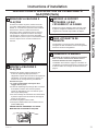
5
PLUG IN THE ICEMAKER
Holding the icemaker in place, insert the
icemaker power cord plug into the socket on the
side wall, making sure the prongs and holes are
matched. Press the plug firmly into the socket.
/RFNWKHSOXJLQSODFHE\FOLSSLQJWKHUHVWUDLQWV
RQWRHDFKVLGHRIWKHSOXJ0DNHVXUHWKH
restraints click into place and the power cord is
still in the hook on the back of the icemaker.
6
MOUNT THE ICEMAKER
Ɣ/LIWWKHLFHPDNHUVRWKHfill tube that was
already installed in the refrigerator fits in the fill
cup opening. Hang the icemaker on the two
mounting screws in the side wall.
Make sure:
Ɣ The power cord is still firmly in the socket.
Ɣ7KHfill tube extends into the fill cup opening
DWWKHEDFNRIWKHLFHPDNHU&KHFNWKHUHDU
of the refrigerator to make sure the fill tube
has not been pushed out of the back of the
refrigerator).
Ɣ7KHLFHPDNHUPRXQWLQJVFUHZVDUHORFDWHGLQ
the uppermost position of the mounting slots
on the icemaker bracket.
Ɣ7KHLFHPDNHULVOHYHO
Ɣ7KHLFHPDNHUSRZHUVZLWFKLVVHWWROFF.
SECURELY TIGHTEN THE ICEMAKER
MOUNTING SCREWS.
8
ATTACH WARRANTY LABEL
A labelLVSURYLGHGZLWKWKLVNLWWRUHFRUGWKH
date of installation for warranty purposes. Apply it
to the back of the refrigerator.
RE-INSTALL THE SHELF
SUPPORT, BUCKET, SHELF
AND BASKET
5HSODFHWKHFHQWHUYHUWLFDOVKHOIVXSSRUWLFH
bucket, chiller shelf and storage basket by
UHYHUVLQJWKHVWHSVLQ6WHS
9
KEEP THIS MANUAL
The warranty for the icemaker is printed in
this manual. Keep this manual with your
Refrigerator Owner’s Manual.
The icemaker installation inside the freezer is
QRZFRPSOHWH&RQWLQXHWRWKHWater Valve
Assembly section on page 14.

12 49-60698 Rev. 7
Installation Instructions
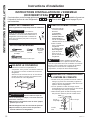
1
REMOVE THE COVER
5HPRYHWKHFRPSUHVVRUFRPSDUWPHQWDFFHVV
FRYHU7KLVUHTXLUHVUHPRYLQJVFUHZVZKLFK
attach the cover to the back of the refrigerator
case.
Be sure to save the screws as the access
cover must be reinstalled later to ensure your
refrigerator will function properly.
2
ATTACH THE WATER VALVE
Ɣ/RFDWHWKHIHPDOH
connector plug.
Plug the female
connector &RQWR
the male terminals
on the water valve
(LWKHUZLUH
can go on either
terminal.
Ɣ)DVWHQWKHZDWHU
valve to the
cabinet by driving
the hex-head
screwIURPWKH
kit into the hole in
the cabinet leg.
CAUTION
6RPHPRGHOVKDYHPXOWLSOHVFUHZ
holes on the cabinet leg. Be sure not to use the
same screw hole as the access cover, and that the
water valve does not interfere with other components
or wires in the compressor compartment, as this may
cause damage.
3
CONNECT WATER TUBE
TO INLET
Ɣ6TXHH]HWKHHQGVRIWKHhose clamp
from the kit with pliers and slide the clamp over
the fill tube assembly, located in the top right
corner of the refrigerator.
Ɣ:KLOHVWLOOVTXHH]LQJWKHFODPSLQVHUWWKH
free end of the water tubeLQWRWKHILOOWXEH
assembly as far as it will go.
Ɣ7KHQVOLGHWKHFODPSGRZQZDUGWRFDSWXUHWKH
water tube in place.
WATER VALVE INSTALLATION INSTRUCTIONS
U
V
W
OR
X
Flat blade and Phillips
screwdrivers
Pliers
6KDUSNQLIH
$UHWKHVHWKHULJKWLQVWUXFWLRQVIRU\RXUPRGHO")ROORZWKH,QVWDOODWLRQ,QVWUXFWLRQVLQGLFDWHGE\WKH
label on the back of the refrigerator -
8
V
W
or
X
. For letter
T
, go to page 14 for instructions.
TOOLS YOU WILL NEED
BEFORE YOU BEGIN
Read these instructions completely and carefully.
WARNING
To reduce the risk of
electric shock or injury during installation,
you must first unplug the refrigerator
before proceeding. Failure to follow
these instructions can result in electrical
shock.
DQG1XWGULYHUV
C
3
9
14
4
Fill tube
assembly
Water tube
&ODPS
3
INSTALLATION INSTRUCTIONS
WARNING
To reduce the risk of death or
electric shock, you must follow these
instructions:
Ŷ Unplug the refrigerator before removing any
panels.
Ŷ Do not damage any wiring while the panel is
removed.
Ŷ Replace all parts and panels before plugging
the refrigerator back in.

49-60698 Rev. 7 13
INSTALLATION INSTRUCTIONS
3
CONNECT WATER TUBE
TO INLET (cont.)
Ɣ8VLQJRQHRIWKHadhesive-backed fasteners
VHFXUHWKHZDWHUWXEHWRWKHEDFNRIWKH
UHIULJHUDWRUDERXWEHORZWKHLQOHW
Ɣ,IWKHZDWHUWXEHLVQRWSXVKHGLQDVIDUDVLW
can go and the hose clamp is not in place over
the fill tube assembly, then leaks are possible.
Installation Instructions
WATER VALVE ASSEMBLY INSTALLATION INSTRUCTIONS
(Continued)
4
INSTALL WATER LINE CLAMP
Ɣ$WWDFKWKHmetal water
line clamp (strain relief)
WRWKHUHIULJHUDWRU
Drive the screwIURP
the kit through the clamp
DWWKHVPDOOLQGHQWLQWR
the back of the cabinet.
Ɣ7KHPHWDOFODPSLVIRUWKHKRXVHZDWHUOLQH
VHHWKH:DWHU/LQH,QVWDOODWLRQ,QVWUXFWLRQV
,WLVQRWWREHXVHGIRUWKHZDWHUWXEHIURPWKH
water valve up to the inlet.
5
ROUTE AND ATTACH THE
WATER TUBE
Ɣ)DVWHQWKHSODVWLFZDWHUWXEHWRWKHEDFNRIWKH
refrigerator with adhesive-backed fasteners
VSDFLQJWKHIDVWHQHUVDVVKRZQWRWDNHXS
slack in the tube.
5
6
6PDOOLQGHQWIRUZDWHU
line clamp installation
Adhesive-backed
fasteners for water tube
6
WATER VALVE INSTALLED
5HIHUWRWKH:DWHU/LQH,QVWDOODWLRQ,QVWUXFWLRQV
for connection to the home water supply. After
water line installation is completed, set the
icemaker power switch to ON.
The icemaking cycle will not begin until the
icemaker and freezer compartment reach
operating temperature, then icemaking will
begin automatically.
REINSTALL THE COVER
5HLQVWDOOWKHFRPSUHVVRUFRPSDUWPHQWDFFHVV
FRYHU7KLVUHTXLUHVXVLQJWKHVFUHZV\RX
removed previously to reattach the cover to
the back of the refrigerator case. This must
be reinstalled for your refrigerator to function
properly.
WARNING
ELECTRIC SHOCK
HAZARD
$WWDFKWXELQJFODPSXVLQJH[LVWLQJKROHRQO\'2
127GULOOLQWRWKHUHIULJHUDWRU

14 49-60698 Rev. 7
2
PLASTIC WATER TUBING
Ɣ5HPRYHZDWHUOLQHIURPWKHYDOYHDVVHPEO\
LQFOXGHGLQWKLVNLWE\UHPRYLQJWKHWXEH
from the clip and pushing on the bottom of the
YDOYHTXLFNFRQQHFWGLVHQJDJLQJWKHWXEHDQG
pulling it from the valve.
Ɣ8VHWKHZDWHUOLQHIURPWKHILOOWXEHDVVHPEO\
that came with the refrigerator. The water line
is attached to the fill tube assembly that is
DOUHDG\LQVWDOOHGLQWKHUHIULJHUDWRU5HPRYH
the plug from the end of the waterline. Without
kinking the water line, route the tube through
the clip on
the valve and
push it into the
TXLFNFRQQHFW
The first white
line on the
tube will be
barely visible
if properly
engaged.
1
REMOVE THE COVER
8VHDRUQXWGULYHURUDQDGMXVWDEOH
wrench to remove the compressor compartment
DFFHVVFRYHU7KLVUHTXLUHVUHPRYLQJVL[
screws which attach the cover to the back of the
refrigerator case.
Be sure to save the screws as the access
cover must be reinstalled later to ensure your
refrigerator will function properly.
3
ATTACH THE BRACKET
EXTENSION TO THE WATER
VALVE
Ɣ8VHD´
nutdriver to
attach the
bracket extension
WRWKHZDWHU
valve bracket
with the screw
WATER VALVE INSTALLATION INSTRUCTIONS
T
- IM4D ONLY
Flat blade and Phillips
screwdrivers
Pliers
6KDUSNQLIH
TOOLS YOU WILL NEED
BEFORE YOU BEGIN
Read these instructions completely and carefully.
WARNING
To reduce the risk of
electric shock or injury during installation,
you must first unplug the refrigerator
before proceeding. Failure to follow
these instructions can result in electrical
shock.
DQG1XWGULYHUV
Installation Instructions
Push up
Quick-connect
Pull down
&OLS
Water line
Quick-connect
&OLS
Water line
Bracket
extension
17
16
INSTALLATION INSTRUCTIONS
WARNING
To reduce the risk of death or
electric shock, you must follow these
instructions:
Ŷ Unplug the refrigerator before removing any
panels.
Ŷ Do not damage any wiring while the panel is
removed.
Ŷ Replace all parts and panels before plugging
the refrigerator back in.

49-60698 Rev. 7 15
INSTALLATION INSTRUCTIONS
Installation Instructions
WATER VALVE ASSEMBLY INSTALLATION INSTRUCTIONS
(Continued)
4
ATTACH THE WATER VALVE TO
THE MACHINE COMPARTMENT
Ɣ/RFDWHWKHIHPDOH
connector plug. Plug the
female connector onto
the male terminals on
the water valve. Either
wire can go on either
terminal.
Ɣ)DVWHQWKHZDWHU
valve to the
cabinet by driving
the hex-head
VFUHZIURP
the kit through
the hole in the
bracket extension
and into the hole
in the cabinet.
5
INSTALL WATER LINE CLAMP
Ɣ,IQRWDOUHDG\SUHVHQW
attach the water line clamp
VWUDLQUHOLHIIURPWKH
kit to the refrigerator. With
the clamp directly in line
with the water valve, drive
the screwIURPWKHNLW
through the clamp at the
indent into the back of the
cabinet.
Ɣ7KHPHWDOFODPSLVIRUWKHKRXVHZDWHUOLQH
VHH:DWHU/LQH,QVWDOODWLRQ,QVWUXFWLRQV,WLV
not to be used for the tubing from the water
valve up to the icemaker.
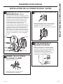
6
ROUTE AND ATTACH THE
PLASTIC WATER LINE
Ɣ)DVWHQWKHSODVWLFZDWHUOLQHWRWKHEDFNRIWKH
cabinet with adhesive-backed fasteners
9
Adhesive-backed
fastener for plastic
water line
4
WATER VALVE INSTALLED
5HIHUWRWKH:DWHU/LQH,QVWDOODWLRQ,QVWUXFWLRQV
for connection to the home water supply. After
water line installation is completed, set the
icemaker power switch to ON.
The icemaking cycle will not begin until the
icemaker and freezer compartment reach
operating temperature, then icemaking will
begin automatically.
8
REINSTALL THE COVER
5HLQVWDOOWKHFRPSUHVVRUFRPSDUWPHQWDFFHVV
FRYHU7KLVUHTXLUHVXVLQJWKHVFUHZV\RX
removed previously to reattach the cover to
the back of the refrigerator case. This must
be reinstalled for your refrigerator to function
properly.
WARNING
ELECTRIC SHOCK
HAZARD
$WWDFKWXELQJFODPSXVLQJH[LVWLQJKROHRQO\'2
127GULOOLQWRWKHUHIULJHUDWRU
5
6

16 49-60698 Rev. 7
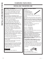
INSTALLING THE WATER LINE
Installation Instructions
BEFORE YOU BEGIN
5HFRPPHQGHGFRSSHUZDWHUVXSSO\NLWVDUH:;;
WX8X3 or WX8X4, depending on the amount of
tubing you need. Approved plastic water supply
OLQHVDUH6PDUW&RQQHFW5HIULJHUDWRU7XELQJ
:;;:;;:;;DQG
WX08X10025).
When connecting your refrigerator to a GE
$SSOLDQFHV5HYHUVH2VPRVLV:DWHU6\VWHPWKHRQO\
DSSURYHGLQVWDOODWLRQLVZLWKD*($SSOLDQFHV59.LW
For other reverse osmosis water systems, follow the
manufacturer’s recommendations.
,IWKHZDWHUVXSSO\WRWKHUHIULJHUDWRULVIURP
D5HYHUVH2VPRVLV:DWHU)LOWUDWLRQ6\VWHP
$1'WKHUHIULJHUDWRUDOVRKDVDZDWHUILOWHUXVH
WKHUHIULJHUDWRU¶VILOWHUE\SDVVSOXJ8VLQJWKH
refrigerator’s water filtration cartridge in conjunction
ZLWKWKH52ILOWHUFDQUHVXOWLQKROORZLFHFXEHVDQG
slower water flow from the water dispenser.
This water line installation is not warranted by
the refrigerator or icemaker manufacturer. Follow
these instructions carefully to minimize the risk of
expensive water damage.
:DWHUKDPPHUZDWHUEDQJLQJLQWKHSLSHVLQKRXVH
plumbing can cause damage to refrigerator parts and
OHDGWRZDWHUOHDNDJHRUIORRGLQJ&DOODTXDOLILHG
plumber to correct water hammer before installing the
water supply line to the refrigerator.
To prevent burns and product damage, do not hook
up the water line to the hot water line.
,I\RXXVH\RXUUHIULJHUDWRUEHIRUHFRQQHFWLQJWKH
water line, make sure the icemaker power switch is in
the OFF position.
Do not install the icemaker tubing in areas where
temperatures fall below freezing.
:KHQXVLQJDQ\HOHFWULFDOGHYLFHVXFKDVDSRZHU
drill) during installation, be sure the device is double
insulated or grounded in a manner to prevent the
hazard of electric shock, or is battery powered.
All installations must be in accordance with local
SOXPELQJFRGHUHTXLUHPHQWV
WARNING
&RQQHFWWRSRWDEOHZDWHUVXSSO\RQO\
WHAT YOU WILL NEED
Ɣ &RSSHURU
6PDUW&RQQHFW
5HIULJHUDWRU7XELQJNLW
RXWHUGLDPHWHUWR
connect the refrigerator to
WKHZDWHUVXSSO\,IXVLQJ
copper, be sure both ends of the tubing are cut
VTXDUH
To determine how much tubing you need: measure
the distance from the water valve on the back of the
refrigerator to the water supply pipe. Then add 8 feet
P%HVXUHWKHUHLVVXIILFLHQWH[WUDWXELQJDERXW
IHHW>P@FRLOHGLQWRWXUQVRIDERXW>FP@
diameter) to allow the refrigerator to move out from
the wall after installation.
6PDUW&RQQHFW5HIULJHUDWRU7XELQJ.LWVDUH
available in the following lengths:
P±:;;
P±:;;
15' P±:;;
P±:;;
Be sure that the kit you select allows at least 8 feet
PDVGHVFULEHGDERYH
NOTE: The only GE Appliances approved plastic
tubing is that supplied in SmartConnect™
Refrigerator Tubing kits. Do not use any other
plastic water supply line because the line is
under pressure at all times. Certain types of
plastic will crack or rupture with age and cause
water damage to your home.
Ɣ A GE Appliances water supply kit FRQWDLQLQJ
tubing, shutoff valve and fittings listed below) is
available at extra cost from your dealer or from
3DUWVDQG$FFHVVRULHV
Ɣ A cold water supply. The water pressure must be
EHWZHHQDQGSVL±NLORSDVFDOVRQ
models without a water filter and between 40 and
SVL±NLORSDVFDOVRQPRGHOVZLWKD
water filter.
Ɣ Power drill.
ƔRUDGMXVWDEOHZUHQFK
Ɣ6WUDLJKWDQG3KLOOLSVEODGHVFUHZGULYHU
INSTALLATION INSTRUCTIONS

49-60698 Rev. 7
INSTALLATION INSTRUCTIONS
Installation Instructions
INSTALLING THE WATER LINE (Continued)
WHAT YOU WILL NEED &RQWLQXHG
Ɣ 7ZRRXWHUGLDPHWHUFRPSUHVVLRQQXWVDQG
IHUUXOHVVOHHYHV²WRFRQQHFWWKHFRSSHUWXELQJ
to the shutoff valve and the refrigerator water valve.
25
Ɣ,I\RXDUHXVLQJD6PDUW&RQQHFW5HIULJHUDWRU
Tubing kit, the necessary fittings are preassembled
to the tubing.
Ɣ,I\RXUH[LVWLQJFRSSHUZDWHUOLQHKDVDIODUHGILWWLQJ
DWWKHHQG\RXZLOOQHHGDQDGDSWHUDYDLODEOHDW
plumbing supply stores) to connect the water line to
WKHUHIULJHUDWRU25\RXFDQFXWRIIWKHIODUHGILWWLQJ
with a tube cutter and then use a compression
ILWWLQJ'RQRWFXWIRUPHGHQGIURP6PDUW&RQQHFW
5HIULJHUDWRUWXELQJ
Ɣ6KXWRIIYDOYHWRFRQQHFWWRWKHFROGZDWHUOLQH
The shutoff valve should have a water inlet
ZLWKDPLQLPXPLQVLGHGLDPHWHURIDWWKH
SRLQWRIFRQQHFWLRQWRWKH&2/':$7(5/,1(
6DGGOHW\SHVKXWRIIYDOYHVDUHLQFOXGHGLQPDQ\
water supply kits. Before purchasing, make sure
a saddle-type valve complies with your local
plumbing codes.
,QVWDOOWKHVKXWRIIYDOYHRQWKHQHDUHVWIUHTXHQWO\XVHG
drinking water line.
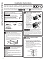
1
SHUT OFF THE MAIN WATER
SUPPLY
Turn on the nearest faucet long enough to clear
the line of water.
2
CHOOSE THE VALVE LOCATION
&KRRVHDORFDWLRQIRUWKHYDOYHWKDWLVHDVLO\
DFFHVVLEOH,WLVEHVWWRFRQQHFWLQWRWKHVLGHRI
a vertical water pipe. When it is necessary to
connect into a horizontal water pipe, make the
connection to the top or side, rather than at the
bottom, to avoid drawing off any sediment from
the water pipe.
3
CHOOSE THE VALVE LOCATION
'ULOODKROHLQWKHZDWHUSLSHHYHQLIXVLQJ
DVHOISLHUFLQJYDOYHXVLQJDVKDUSELW5HPRYH
any burrs resulting from drilling the hole in the
pipe. Take care not to allow water to drain into
the drill. )DLOXUHWRGULOODKROHPD\UHVXOW
in reduced ice production or smaller cubes.
4
FASTEN THE SHUTOFF VALVE
Fasten the shutoff valve to the cold water pipe
with the pipe clamp.
NOTE: &RPPRQZHDOWKRI0DVVDFKXVHWWV
3OXPELQJ&RGHV&05VKDOOEHDGKHUHGWR
6DGGOHYDOYHVDUHLOOHJDODQGXVHLVQRWSHUPLWWHG
LQ0DVVDFKXVHWWV&RQVXOWZLWK\RXUOLFHQVHG
plumber.
9HUWLFDO&ROG
Water Pipe
6DGGOH7\SH
6KXWRႇ9DOYH
3LSH&ODPS

18 49-60698 Rev. 7
INSTALLING THE WATER LINE (Continued)
Installation Instructions
5
TIGHTEN THE PIPE CLAMP
Tighten the clamp screws until the sealing
washer begins to swell.
NOTE: Do not overtighten or you may crush
the tubing.
8
FLUSH OUT THE TUBING
Turn the main water supply on and flush out the
tubing until the water is clear.
6KXWWKHZDWHURIIDWWKHZDWHUYDOYHDIWHUDERXW
RQHTXDUWOLWHURIZDWHUKDVEHHQIOXVKHG
through the tubing.
9
CONNECT THE TUBING TO THE
REFRIGERATOR
NOTES:
Ɣ%HIRUHPDNLQJWKHFRQQHFWLRQWRWKH
refrigerator, be sure the refrigerator power cord
is not plugged into the wall outlet.
Ɣ,I\RXUUHIULJHUDWRUGRHVQRWKDYHDZDWHUILOWHU
we recommend installing one if your water
supply has sand or particles that could clog the
VFUHHQRIWKHUHIULJHUDWRU¶VZDWHUYDOYH,QVWDOOLW
LQWKHZDWHUOLQHQHDUWKHUHIULJHUDWRU,IXVLQJ
6PDUW&RQQHFW5HIULJHUDWRU7XELQJNLW\RX
ZLOOQHHGDQDGGLWLRQDOWXEH:;;
to connect the filter. Do not cut plastic tube to
install filter.
5HPRYHWKHSODVWLFIOH[LEOH
cap from the water valve
UHIULJHUDWRUFRQQHFWLRQ
NOTE:&RPPRQZHDOWKRI0DVVDFKXVHWWV
3OXPELQJ&RGHV&05VKDOOEHDGKHUHGWR
6DGGOHYDOYHVDUHLOOHJDODQGXVHLVQRWSHUPLWWHG
LQ0DVVDFKXVHWWV&RQVXOWZLWK\RXUOLFHQVHG
plumber.
6
ROUTE THE TUBING
5RXWHWKHWXELQJEHWZHHQWKHFROGZDWHUOLQHDQG
the refrigerator.
5RXWHWKHWXELQJWKURXJKDKROHGULOOHGLQWKHZDOO
RUIORRUEHKLQGWKHUHIULJHUDWRURUDGMDFHQWEDVH
cabinet) as close to the wall as possible.
NOTE: Be sure there is sufficient extra tubing
DERXWIHHW>FP@FRLOHGLQWRWXUQVRIDERXW
>FP@GLDPHWHUWRDOORZWKHUHIULJHUDWRUWR
move out from the wall after installation.
CONNECT THE TUBING TO
THE VALVE (Continued)
)RUSODVWLFWXELQJIURPD6PDUW&RQQHFW
5HIULJHUDWRU7XELQJNLWLQVHUWWKHPROGHGHQG
of the tubing into the shutoff valve and tighten
compression nut until it is hand tight, then tighten
RQHDGGLWLRQDOWXUQZLWKDZUHQFK2YHUWLJKWHQLQJ
may cause leaks.
CONNECT THE TUBING TO
THE VALVE
3ODFHWKHFRPSUHVVLRQQXWDQGIHUUXOHVOHHYH
for copper tubing onto the end of the tubing and
connect it to the shutoff valve.
0DNHVXUHWKHWXELQJLVIXOO\LQVHUWHGLQWRWKH
valve. Tighten the compression nut securely.
Washer
,QOHW(QG
3LSH&ODPS
&ODPS
6FUHZ
6DGGOH7\SH
6KXWRႇ9DOYH
&RPSUHVVLRQ1XW
6PDUW&RQQHFW
Tubing
3DFNLQJ1XW
2XWOHW9DOYH
)HUUXOHVOHHYH
INSTALLATION INSTRUCTIONS

49-60698 Rev. 7 19
INSTALLATION INSTRUCTIONS
Installation Instructions
INSTALLING THE WATER LINE (Continued)
9
CONNECT THE TUBING TO THE
REFRIGERATOR &RQWLQXHG
3ODFHWKHFRPSUHVVLRQQXWDQGIHUUXOHVOHHYH
RQWRWKHHQGRIWKHWXELQJDVVKRZQ2Q
6PDUW&RQQHFW5HIULJHUDWRU7XELQJNLWWKHQXWV
are already assembled to the tubing.
,QVHUWWKHHQGRIWKHWXELQJLQWRWKHZDWHUYDOYH
connection as far as possible. While holding the
tubing, tighten the fitting.
)RUSODVWLFWXELQJIURPD6PDUW&RQQHFW
5HIULJHUDWRU7XELQJNLWLQVHUWWKHPROGHGHQGRI
the tubing into the refrigerator connection and
tighten compression nut until it is hand tight,
then tighten one additional turn with a wrench.
2YHUWLJKWHQLQJPD\FDXVHOHDNV
Fasten the tubing into the clamp provided to
hold it in a vertical position. You may need to pry
open the clamp.
Tubing
&ODPS
&RPSUHVVLRQ
1XW
6PDUW&RQQHFW
Tubing
5HIULJHUDWRU
&RQQHFWLRQ
7XELQJ
Ferrule
VOHHYH
10
TURN THE WATER ON AT THE
SHUTOFF VALVE
Tighten any connections that leak.
5HDWWDFKWKHFRPSUHVVRUFRPSDUWPHQWDFFHVV
cover.
11
PLUG IN THE REFRIGERATOR
Arrange the coil of tubing so that it does not
vibrate against the back of the refrigerator or
against the wall. Push the refrigerator back to
the wall.
12
START THE ICEMAKER
6HWWKHLFHPDNHUSRZHUVZLWFKWRWKH21
position. The icemaker will not begin to operate
until it reaches its operating temperature of 15°F
±&RUEHORZ,WZLOOWKHQEHJLQRSHUDWLRQ
automatically if the icemaker power switch is in
WKH21SRVLWLRQ

20 49-60698 Rev. 7
Troubleshooting Tips... Before you call for service
6DYHWLPHDQGPRQH\5HYLHZWKHFKDUWVRQWKHIROORZLQJSDJHVILUVWDQG\RXPD\QRWQHHGWRFDOOIRUVHUYLFH,I
needed, service can be scheduled by visiting us online GEAppliances.comRUFDOOLQJ*(&$5(6
,Q&DQDGDYLVLW*($SSOLDQFHVFDRUFDOO
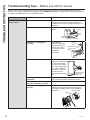
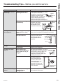
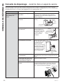
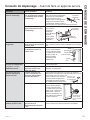
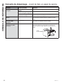
Problem Possible Causes What to Do
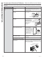
Automatic icemaker
does not work
Freezer compartment too warm. After installing the kit, allow the refrigerator to
FRPSOHWHO\FRROGRZQIRUKRXUV2QFHWKH
compartment is cool, the icemaker will begin ice
production.
Icemaker is not turned on. 0RYHWKHLFHPDNHUSRZHUVZLWFKWRWKH21
position.
Icemaker is not plugged in
correctly.
&KHFNWKDWWKH
icemaker cord plug is
fully inserted into the
VRFNHW6HH3OXJLQ
WKHLFHPDNHULQWKH
,QVWDOODWLRQ
,QVWUXFWLRQV
Water line kinked. &KHFNWKDWWKHSODVWLF
water line running from
the valve to the water
tube inlet is not kinked.
6HH&RQQHFWWKHZDWHU
OLQHLQWKH,QVWDOODWLRQ
,QVWUXFWLRQV$NLQNLQ
the water line will
restrict flow to the water
line.
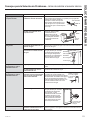
Water supply turned off or not
connected.
After installing the kit, make sure the house water
supply to the refrigerator has been turned on.
Piled up cubes in the storage bin
cause the icemaker to shut off.
/HYHOFXEHVE\KDQG
Water valve is not plugged in
correctly.
&KHFNWKDWWKHYDOYHZLUHDGDSWHULVFRPSOHWHO\
plugged onto the terminals on the water valve.
6HH$WWDFKWKHZDWHUYDOYHLQWKH,QVWDOODWLRQ
,QVWUXFWLRQV
Feeler
Arm
Power
6ZLWFK
,FHPDNHU
(Appearance may vary)
&OLS5HVWUDLQWVRQWR
/RFNLQJ7DEV
/RFNLQJ
Tabs
Hook
Adhesive-backed
Fasteners for
Water Tube
Adapter
Valve Terminals
TROUBLESHOOTING TIPS
La page est en cours de chargement...
La page est en cours de chargement...
La page est en cours de chargement...
La page est en cours de chargement...
La page est en cours de chargement...
La page est en cours de chargement...
La page est en cours de chargement...
La page est en cours de chargement...
La page est en cours de chargement...
La page est en cours de chargement...
La page est en cours de chargement...
La page est en cours de chargement...
La page est en cours de chargement...
La page est en cours de chargement...
La page est en cours de chargement...
La page est en cours de chargement...
La page est en cours de chargement...
La page est en cours de chargement...
La page est en cours de chargement...
La page est en cours de chargement...
La page est en cours de chargement...
La page est en cours de chargement...
La page est en cours de chargement...
La page est en cours de chargement...
La page est en cours de chargement...
La page est en cours de chargement...
La page est en cours de chargement...
La page est en cours de chargement...
La page est en cours de chargement...
La page est en cours de chargement...
La page est en cours de chargement...
La page est en cours de chargement...
La page est en cours de chargement...
La page est en cours de chargement...
La page est en cours de chargement...
La page est en cours de chargement...
La page est en cours de chargement...
La page est en cours de chargement...
La page est en cours de chargement...
La page est en cours de chargement...
La page est en cours de chargement...
La page est en cours de chargement...
La page est en cours de chargement...
La page est en cours de chargement...
La page est en cours de chargement...
La page est en cours de chargement...
La page est en cours de chargement...
La page est en cours de chargement...
La page est en cours de chargement...
La page est en cours de chargement...
La page est en cours de chargement...
La page est en cours de chargement...
-
 1
1
-
 2
2
-
 3
3
-
 4
4
-
 5
5
-
 6
6
-
 7
7
-
 8
8
-
 9
9
-
 10
10
-
 11
11
-
 12
12
-
 13
13
-
 14
14
-
 15
15
-
 16
16
-
 17
17
-
 18
18
-
 19
19
-
 20
20
-
 21
21
-
 22
22
-
 23
23
-
 24
24
-
 25
25
-
 26
26
-
 27
27
-
 28
28
-
 29
29
-
 30
30
-
 31
31
-
 32
32
-
 33
33
-
 34
34
-
 35
35
-
 36
36
-
 37
37
-
 38
38
-
 39
39
-
 40
40
-
 41
41
-
 42
42
-
 43
43
-
 44
44
-
 45
45
-
 46
46
-
 47
47
-
 48
48
-
 49
49
-
 50
50
-
 51
51
-
 52
52
-
 53
53
-
 54
54
-
 55
55
-
 56
56
-
 57
57
-
 58
58
-
 59
59
-
 60
60
-
 61
61
-
 62
62
-
 63
63
-
 64
64
-
 65
65
-
 66
66
-
 67
67
-
 68
68
-
 69
69
-
 70
70
-
 71
71
-
 72
72


GE IM4LED Le manuel du propriétaire
- Catégorie
- Frigos
- Taper
- Le manuel du propriétaire
- Ce manuel convient également à
dans d''autres langues
- English: GE IM4LED Owner's manual
- español: GE IM4LED El manual del propietario