Sauder Cottage Road 418072 Mode d'emploi
- Taper
- Mode d'emploi

Need help? Visit Sauder.com to view video assembly tips or chat with a live rep.
Prefer the phone? Call 1-800-523-3987.
Share your journey!
sauder.com
For all your
newfangled gadgetry.
NOTE: THIS INSTRUCTION
BOOKLET CONTAINS IMPORTANT
SAFETY INFORMATION.
PLEASE READ AND KEEP FOR
FUTURE REFERENCE.
English pg 1-22
Français pg 23-25
Español pg 26-28
Lot # 366632 11/24/14
Purchased: __________________
Be sure to give us a ring before
making any returns. 1-800-523-3987
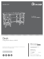
Desk
Cottage Road Collection | 418072

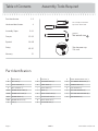
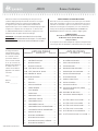
Table of Contents Assembly Tools Required
Part Identifi cation
Hardware Identifi cation
Assembly Steps
Français
Español
Safety
Warranty
Hammer
Not actual size
No. 2 Phillips Screwdriver
Tip Shown Actual Size
Skip the power trip.
This time.
2-3
4
5-22
23-25
26-28
29-30
31
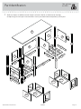
Part Identifi cation
A RIGHT END (1)
B LEFT END (1)
C RIGHT UPRIGHT (1)
D LEFT UPRIGHT (1)
D48 DRAWER RIGHT SIDE (2)
D49 DRAWER LEFT SIDE (2)
D151 DRAWER BACK (2)
D953 DRAWER BOTTOM (2)
E TOP (1)
F BOTTOM (2)
G OUTER BOTTOM (4)
H LARGE BACK (1)
I SMALL BACK (2)
J BRACE (1)
K RIGHT FRONT LEG (2)
L LEFT FRONT LEG (2)
M RIGHT REAR LEG (1)
N LEFT REAR LEG (1)
O RIGHT MIDDLE REAR LEG (1)
P LEFT MIDDLE REAR LEG (1)
Q DRAWER FRONT (2)
R TOP MOLDING (1)
S BOTTOM MOLDING (4)
T BOTTOM SIDE MOLDING (4)
U END MOLDING (2)
418072 www.sauder.com/servicesPage 2

å While not all parts are labeled, some of the parts will have a label or an inked letter on the edge
to help distinguish similar parts from each other. Use this part identifi cation to help identify similar parts.
Now you know
our ABCs.
Part Identifi cation
A
B
C
D
E
F
F
G
G
G
G
H
I
I
J
K
K
L
L
M
N
O
P
Q
Q
R
S
S
S
S
T
T
T
T
U
U
D48D151
D953
D953
D151
D49
D49
D48
418072www.sauder.com/services
Page 3

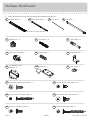
Hardware Identifi cation
å Screws are shown actual size. You may receive extra hardware with your unit.
SILVER 1/2" MACHINE SCREW - 2
38S
METAL BRACKET - 3
4G
BLACK 9/16" LARGE HEAD SCREW - 14
1S
12F
TWIST-LOCK
®
FASTENER - 2
BLACK 2" PAN HEAD SCREW - 4
66S
CAM COVER - 4
19P
3S
GOLD 5/16" FLAT HEAD SCREW - 16
BLACK 9/16" FLAT HEAD SCREW - 4
32S
CAM SCREW - 44
8F
WOOD DOWEL - 4
15F
30S
BLACK 1-9/16" FLAT HEAD SCREW - 8
HIDDEN CAM - 72
1F
CAM DOWEL - 28
2F
100K
KNOB SET - 2
FILE DRAWER FRONT
BRACKET - 4
10G
FILE GLIDE - 2
4B
W
EXTENSION SLIDE - 4
V
EXTENSION RAIL - 4
(EXTENSION SET SHOWN SEPARATED)
418072 www.sauder.com/servicesPage 4
FILE ROD - 2
7B

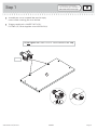
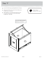
Step 1
Look for this icon. It means a
video assembly tip is available at
www.sauder.com/services/tips
å
Assemble your unit on a carpeted fl oor or on the empty
carton to avoid scratching your unit or the fl oor.
å
To begin assembly, push a SAUDER TWIST-LOCK®
FASTENER (12F) into the large holes in the LARGE BACK (H).
418072www.sauder.com/services
Page 5
Do not tighten the TWIST-LOCK® FASTENERS in this step.
12F
H
(2 used)

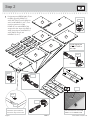
å
Push seventy-two HIDDEN CAMS (1F) into
the ENDS (A and B), UPRIGHTS (C
and D), BOTTOMS (F and G), BACKS (H
and I), and MOLDINGS (S and T). Then,
insert the metal end of a CAM
DOWEL (2F) into each HIDDEN CAM,
except in the short edges of the ENDS (A
and B), short edges of the UPRIGHTS (C
and D), BACKS (H and I) and
MOLDINGS (S and T).
Step 2
418072 www.sauder.com/servicesPage 6
I
I
F
F
G
G
G
G
A
B
C
D
T
T
T
T
S
S
S
S
H
Arrow
Arrow
1F
The arrow in the HIDDEN
CAM must point toward the
hole in the edge of the board.
Hole
Arrow
1F
2F
Arrow
1F
2F
1F
Arrow
(72 used)
(28 used)
Arrow
1F
2F
Do not tighten the
HIDDEN CAMS in
this step.
Insert the metal end of the CAM
DOWEL into the HIDDEN CAM.
Arrow

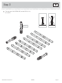
Step 3
418072www.sauder.com/services
Page 7
å
Turn forty-four CAM SCREWS (8F) into the LEGS (K, L, M,
N, O, and P).
K
K
L
L
M
N
O
P
8F
8F
8F
(44 used)

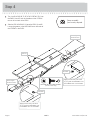
å
Turn four BLACK 9/16" FLAT HEAD SCREWS (32S) into
the ENDS (A and B) until the shoulders of the SCREWS
rest on the surfaces of the ENDS.
å
Slide the END MOLDINGS (U) onto the ENDS (A and B).
Line up the grooves in the MOLDINGS over the heads of
the SCREWS in the ENDS.
Step 4
418072 www.sauder.com/servicesPage 8
These edges
should be even.
These edges
should be even.
Shoulder
Shoulder
Apply pressure with your hands
as you guide the MOLDINGS over
the SCREWS and onto the ENDS.
Apply pressure with your hands
as you guide the MOLDINGS over
the SCREWS and onto the ENDS.
BLACK 9/16" FLAT HEAD SCREW
(4 used in this step)
32S
A
B
U
U
Groove
Some assembly
(and snacks) required.

å
Flip the ENDS (A and B) over.
å
Fasten the LEGS (K and M) and a BOTTOM SIDE
MOLDING (T) to the RIGHT END (A). Tighten six
HIDDEN CAMS.
å
Fasten the LEGS (L and N) and a BOTTOM SIDE
MOLDING (T) to the LEFT END (B). Tighten six
HIDDEN CAMS.
Step 5
418072www.sauder.com/services
Page 9
A
B
T
T
K
M
L
N
Surface with HIDDEN CAMS
Surface with
HIDDEN CAMS
Surface with
HIDDEN CAMS
These edges must be even.
These edges must be even.
1
2
LEFT END ASSEMBLY
RIGHT END ASSEMBLY

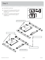
å
Fasten the LEGS (L and O) and a BOTTOM SIDE
MOLDING (T) to the UPRIGHT (C). Tighten six
HIDDEN CAMS.
å
Fasten the LEGS (K and P) and a BOTTOM SIDE
MOLDING (T) to the LEFT UPRIGHT (D). Tighten six
HIDDEN CAMS.
Step 6
418072 www.sauder.com/servicesPage 10
L
O
T
T
Surface with HIDDEN CAMS
C
D
Surface with
HIDDEN CAMS
Surface with
HIDDEN CAMS
K
P
1
2

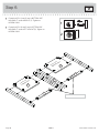
å
Separate the EXTENSION SLIDES (W) from the EXTENSION RAILS (V) as shown in the enlarged diagram below. Be
prepared, the parts are greasy.
å
Fasten the EXTENSION RAILS (V) to the ENDS (A and B) and UPRIGHTS (C and D). Use eight GOLD 5/16" FLAT
HEAD SCREWS (3S).
å
NOTE: For each EXTENSION RAIL, turn a SCREW into the hole shown in the enlarged diagram. Then, slide the inner cartridge
of the EXTENSION RAIL in to fi nd the other hole that lines up with the hole in the END. Turn a SCREW into this hole.
Step 7
418072www.sauder.com/services
Page 11
Open end
Open end
Open end
Open end
GOLD 5/16" FLAT HEAD SCREW
(8 used in this step)
3S
Push the black lever in and pull the SLIDE from the RAIL.
A
B
C
D
V
V
V
V
V
W
LEFT END ASSEMBLY
RIGHT END ASSEMBLY

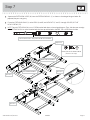
å
Insert a WOOD DOWEL (15F) into each short edge of
a BOTTOM (F).
å
Lay two OUTER BOTTOMS (G) next to the BOTTOM (F)
as shown.
å
Fasten two BOTTOM MOLDINGS (S) to the BOTTOMS (F
and G). Tighten six HIDDEN CAMS.
å
NOTE: Be sure the WOOD DOWELS insert into the
BOTTOM MOLDINGS.
å
Repeat this step for the remaining BOTTOMS (F and G)
and BOTTOM MOLDINGS (S).
Step 8
418072 www.sauder.com/servicesPage 12
S
S
F
G
G
Surface with
HIDDEN CAMS
Surface with
HIDDEN CAMS
Surface with
HIDDEN CAMS
Edge with CAM DOWELS
Edge with CAM DOWELS
15F
15F
Start Tighten
Arrow
Minimum
190 degrees
Caution
Risk of damage or
injury. HIDDEN CAMS
must be completely
tightened. HIDDEN
CAMS that are not
completely tightened
may loosen, and parts
may separate. To
completely tighten:
Arrow
Maximum
210 degrees
BOTTOM ASSEMBLY
(4 used in this step)

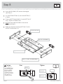
å
Fasten the MIDDLE REAR LEGS (O and P) to the LARGE
BACK (H). Tighten four HIDDEN CAMS.
å
Fasten the BRACE (J) to the MIDDLE REAR LEGS (O and P).
Use four BLACK 2" PAN HEAD SCREWS (66S).
Step 9
418072www.sauder.com/services
Page 13
Surface with
HIDDEN CAMS
Arrow
Minimum
190 degrees
Maximum
210 degrees
O
P
J
H
Edge with
TWIST-LOCK®
FASTENERS
BLACK 2" PAN HEAD SCREW
(4 used in this step)
66S

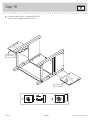
å
Fasten the SMALL BACKS (I) to the
MIDDLE REAR
LEGS (O and P). Tighten four HIDDEN CAMS.
Step 10
418072 www.sauder.com/servicesPage 14
Surface with
HIDDEN CAMS
Surface
with
HIDDEN
CAMS
O
P
I
I
12
Finished edge
Finished edge

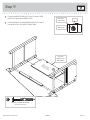
å
Fasten a BOTTOM assembly to the LEGS (L and O)
and BOTTOM SIDE MOLDING (T). Tighten four
HIDDEN CAMS.
å
Fasten the remaining BOTTOM assembly to the LEGS (K
and P) and BOTTOM SIDE MOLDING (T). Tighten four
HIDDEN CAMS.
Step 11
418072www.sauder.com/services
Page 15
Surface with
HIDDEN CAMS
Surface with
HIDDEN CAMS
Arrow
Minimum
190 degrees
Maximum
210 degrees
K
L
O
P
T
T
BOTTOM ASSEMBLY
BOTTOM ASSEMBLY
12

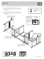
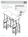
å
Fasten the LEFT END ASSEMBLY to the SMALL BACK (I) and
BOTTOM ASSEMBLY on the left end of your unit. Tighten six
HIDDEN CAMS.
å
Fasten the RIGHT END ASSEMBLY to the SMALL BACK (I) and
BOTTOM ASSEMBLY on the right end of your unit. Tighten six
HIDDEN CAMS.
Step 12
418072 www.sauder.com/servicesPage 16
12
Arrow
Minimum
190 degrees
Maximum
210 degrees
LEFT END ASSEMBLY
RIGHT END ASSEMBLY
BOTTOM ASSEMBLY
BOTTOM ASSEMBLY
I
I
Now might be a
good time to refresh
your drink.

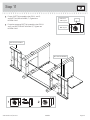
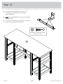
å
Carefully stand your unit upright.
å
Fasten the TOP (E) to the ENDS (A and B) and
UPRIGHTS (C and D). Tighten eight HIDDEN CAMS.
å
Fasten the TOP (E) to the LARGE BACK (H). Tighten two
TWIST-LOCK® FASTENERS.
Step 13
418072www.sauder.com/services
Page 17
A
B
C
D
H
How to use the SAUDER TWIST-LOCK
®
FASTENER
1. Insert the dowel end of the FASTENER into the hole of the
adjoining part.
NOTE: The dowel end of the FASTENER must remain fully
inserted in the hole of the adjoining part while locking
the FASTENER.
2. Tighten the FASTENER with a Phillips screwdriver as tight
as possible.
Dowel end
E

å
Fasten three METAL BRACKETS (4G) to the TOP
MOLDING (R). Use three BLACK 9/16" LARGE
HEAD SCREWS (1S).
å
NOTE: Be sure the BRACKETS are even with the edges
of the MOLDING.
å
Fasten the TOP MOLDING (R) to the TOP (E). Use three
BLACK 9/16" LARGE HEAD SCREWS (1S).
Step 14
418072 www.sauder.com/servicesPage 18
BLACK 9/16" LARGE HEAD SCREW
(6 used in this step)
1S
4G
R
R
E

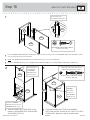
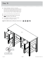
Step 15
418072www.sauder.com/services
Page 19
1
3
2
UNFINISHED
å
Pull the DRAWER FRONT BRACKETS (10G) apart and slide them into the grooves in the DRAWER SIDES (D48 and D49). You may
need to gently tap them in with a hammer.
å
NOTE: The DRAWER FRONT BRACKETS are marked “RH” and “LH” for easy identifi cation.
å
Fasten the DRAWER FRONT (Q) to the DRAWER FRONT BRACKETS (10G). Use four BLACK 9/16" LARGE HEAD SCREWS (1S).
å
Slide the DRAWER BOTTOM (D953) into the
grooves in the DRAWER SIDES (D48 and D49)
and DRAWER FRONT (Q).
å
Fasten the DRAWER BACK (D151) to the DRAWER
SIDES (D48 and D49). Use four BLACK 1-9/16" FLAT HEAD
SCREWS (30S). Repeat this step for the other drawer.
BLACK 9/16" LARGE HEAD SCREW
(8 used in this step)
1S
D48
D48
D48
D953
D151
D49
D49
D49
Q
Start each screw a few turns before
completely tightening any of them.
BLACK 1-9/16" FLAT HEAD SCREW
(8 used in this step)
30S
Be sure the DRAWER
BOTTOM inserts into the
DRAWER FRONT groove.
Be sure the
DRAWER
BOTTOM
inserts into
the DRAWER
BACK groove.
With the palm of
your hand, tap
the DRAWER
BOTTOM down
into the groove.
Tap down with your
screwdriver and hammer.
D49
10G
Q
VIEW THE T-SLOT BOX VIDEO

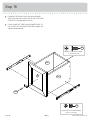
å
Fasten the EXTENSION SLIDES (W) to the DRAWER
SIDES (D48 and D49). Use four GOLD 5/16" FLAT HEAD
SCREWS (3S) through holes #1 and #3.
å
Fasten a KNOB SET (100K) to the DRAWER FRONT (Q).
Use a SILVER 1/2" MACHINE SCREW (38S). Repeat this
step for the other drawer.
Step 16
418072 www.sauder.com/servicesPage 20
W
W
D48
D49
100K
Q
SILVER 1/2" MACHINE SCREW
(2 used in this step)
38S
GOLD 5/16" FLAT HEAD SCREW
(8 used in this step)
3S
1
1
2
2
3
3
La page est en cours de chargement...
La page est en cours de chargement...
La page est en cours de chargement...
La page est en cours de chargement...
La page est en cours de chargement...
La page est en cours de chargement...
La page est en cours de chargement...
La page est en cours de chargement...
La page est en cours de chargement...
La page est en cours de chargement...
La page est en cours de chargement...
La page est en cours de chargement...
-
 1
1
-
 2
2
-
 3
3
-
 4
4
-
 5
5
-
 6
6
-
 7
7
-
 8
8
-
 9
9
-
 10
10
-
 11
11
-
 12
12
-
 13
13
-
 14
14
-
 15
15
-
 16
16
-
 17
17
-
 18
18
-
 19
19
-
 20
20
-
 21
21
-
 22
22
-
 23
23
-
 24
24
-
 25
25
-
 26
26
-
 27
27
-
 28
28
-
 29
29
-
 30
30
-
 31
31
-
 32
32


Sauder Cottage Road 418072 Mode d'emploi
- Taper
- Mode d'emploi
dans d''autres langues
Documents connexes
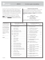
-
Sauder 410627 Mode d'emploi
-
-
-
-
-
-
-
-
-
