
2181051A
www.sears.com
Sears Roebuck and Co., Hoffman Estates, IL 60179 U.S.A.
Sears Canada, Inc., Toronto, Ontario, Canada M5B 2B8
Clear Ice Maker
Use & Care Guide
Fábrica de hielo transparente
Manual de Uso y Cuidado
Machine à glaçons transparents
Guide d’utilisation et d’entretien
Models, Modelos, Modèles: 86482, 86485
ENGLISH ESPAÑOL FRANÇAIS

2
CONTENTS
Page
Warranty...........................................................................2
Ice Maker Safety..............................................................3
Parts and Features..........................................................3
Installation Instructions..................................................4
Electrical requirements ...............................................4
Space requirements....................................................4
Unit wiring diagrams...................................................5
Installing the ice maker...............................................5
Checking operation.....................................................6
Changing the door panels...........................................7
Operating Instructions....................................................8
How the ice maker makes ice.....................................8
Things to remember....................................................8
Setting the controls.....................................................8
General Cleaning and Care ............................................9
Cleaning exterior surfaces..........................................9
Cleaning and sanitizing the ice making system..........9
Cleaning the condenser............................................10
Removing and cleaning the interior components .....10
Filtering and treating water .......................................11
Vacation and Moving Care ...........................................12
Before Calling for Service ............................................13
Sears Toll Free Numbers..............................................40
Warranty
FULL ONE-YEAR WARRANTY
For one year from the date of purchase, when the ice maker
is used for residential use and is operated and maintained
according to instructions attached to or furnished with the ice
maker, Sears will repair the ice maker free of charge, if de-
fective in materials or workmanship.
LIMITED ONE-YEAR WARRANTY
For one year from the date of purchase, when the ice maker
is used for commercial use and is operated and maintained
according to instructions attached to or furnished with the ice
maker, Sears will provide, free of charge, replacement parts
for any parts defective in materials or workmanship. You pay
for labor.
FULL FIVE-YEAR WARRANTY
ON SEALED REFRIGERATION
SYSTEM
For five years from the date of purchase, when the product is
operated and maintained according to instructions attached
to or furnished with the product, Sears will repair the sealed
system (consisting of: refrigerant, connecting tubing, and
compressor motor), free of charge, if defective in materials or
workmanship.
This warranty gives you specific legal rights, and you may
also have other rights which vary from state to state.
WARRANTY SERVICE IS AVAILABLE BY SIMPLY CON-
TACTING THE NEAREST SEARS STORE OR
SERVICE CENTER THROUGHOUT THE UNITED STATES.
Sears, Roebuck and Co. • D/817 WA • Hoffman Estates, IL 60179
COPY YOUR MODEL AND SERIAL NUMBERS HERE.
When you need service, or call with a question, have this
information ready:
Model Number
Serial Number
Purchase Date
Sears Service Center
and Telephone Number

3
ENGLISH
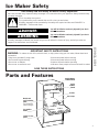
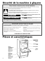
Parts and Features
Model and
serial number
plate
(on left interior
cabinet flange)
Ice retainer
baffle
Lower access
panel
Ice thickness
control knob
Ice bin
Ice scoop
Cycle
control
knob
Ice Maker Safety
You will be killed or seriously injured if you don’t
follow instructions.
You can be killed or seriously injured if you don’t
follow instructions.
Your safety and the safety of others is very important.
We have provided many important safety messages in this manual and on your appliance. Always read and obey
all safety messages.
This is the safety alert symbol.
This symbol alerts you to hazards that can kill or hurt you and others.
All safety messages will be preceded by the safety alert symbol and the word “DANGER” or
“WARNING.” These words mean:
wDANGER
wWARNING
All safety messages will identify the hazard, tell you how to reduce the chance of injury, and tell you what can
happen if the instructions are not followed.
IMPORTANT SAFETY INSTRUCTIONS
WARNING:
To reduce the risk of fire, electric shock, or injury when using your ice maker, follow these basic
precautions:
• Plug into a grounded 3 prong outlet.
• Do not remove ground prong.
• Do not use an adapter.
• Do not use an extension cord.
SAVE THESE INSTRUCTIONS
• Disconnect power before cleaning.
• Disconnect power before servicing.
• Replace all panels before operating.
• Use two or more people to move and install ice maker.

4
Electrical requirements
Electrical requirements
A 115 Volt, 60 Hz., AC only, 15 ampere fused electrical supply
circuit, properly grounded in accordance with the National
Electrical Code and local codes and ordinances, is required.
It is recommended that a separate circuit, serving only this
appliance, be provided. Use a receptacle which cannot be
turned off with a switch or pull chain.
NOTE: A time delay fuse or circuit breaker is recommended.
Grounding method
For your personal safety, this appliance must be grounded.
This appliance is equipped with a power supply cord having
a 3 prong grounding plug. To minimize possible shock
hazard, the cord must be plugged into a mating, 3 prong,
grounding-type wall receptacle, grounded in accordance with
the National Electrical Code and local codes and ordinances.
If a mating wall receptacle is not available, it is the personal
responsibility of the customer to have a properly-grounded,
3 prong wall receptacle installed by a qualified electrician.
wWARNING
Electrical Shock Hazard
Plug into a grounded 3 prong outlet.
Do not remove ground prong.
Do not use an adapter.
Do not use an extension cord.
Failure to follow these instructions can result in
death, fire, or electrical shock.
Installation Instructions
3-prong grounding
type wall receptacle
Ground prong
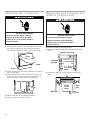
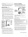
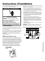
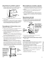
Space requirements
• To ensure proper ventilation for your ice maker, the front
side must be completely unobstructed. The unit may be
closed-in on the top and three sides, but the installation
should allow the ice maker to be pulled forward for servicing
if necessary.
• Installation of the ice maker requires a cold water supply
inlet of
1
⁄4" (6 mm) OD soft copper tubing with a shut-off
valve and either a gravity-drain system or condensate pump
to carry the water to an existing drain.
• Choose a well ventilated area with temperatures above 55°F
(13°C) and below 110°F (43°C). Best results are obtained
between 70°F (21°C) and 90°F (32°C). This unit MUST be
installed in an area protected from the elements, such as
wind, rain, water spray, or drip.
• When installing the ice maker under a counter, follow the
recommended opening dimensions shown.
NOTE: Do not kink or pinch the power supply cord between
the ice maker and cabinet.
Built-in Opening Dimensions
34
1
⁄2"
(88 cm)
90°
90°
9" max
(23 cm)
Locate
outlet within
this space
18" (46 cm)
4
1
⁄2" (11.5 cm)
To center line

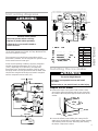
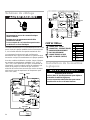
Unit wiring diagrams
This model operates at 115 Volts, except for the cutter grid
circuit which operates at 8.5 Volts at 1 Amp. Maximum fuse
size used should be 15 amps.
The compressor runs at all times except when the bin
thermostat is satisfied. This de-energizes the system except
for the transformer and cutter grid.
Under normal operating conditions, when the evaporator
reaches the preset temperature (10°F [-12°C] to -3°F
[-19°C], depending on ice thickness), the evaporator
thermostat opens, terminating operation of the fan motor
and pump motor. The hot gas solenoid and the water valve
solenoid are energized at this time and remain energized
until the evaporator reaches 38°F (3°C).
2
3
CLEAN
OFF
ON
SERVICE
SWITCH
8.5 V
115 V
GRID
TRANSFORMER
COMPRESSOR
START RELAY
OVERLOAD
WATER PUMP
CONDENSER
FAN
115 VOLTS
60 HERTZ
NC
NC
3
2
BIN
THERMOSTAT
EVAPORATOR
THERMOSTAT
L N
R
S
1
1
HOT GAS
6
5
Y
OR
BK
BK
OR
BK
SOL
W
W
W
W
W
W Y
CUTTER
WATER
VALVE
SOL
R
BL
BK / W
BK / W
BK
C
3
2
1
3
2
1
BK / W
Y
BIN
THERMO
EVAP
THERMO
SERVICE
SWITCH
BK/ W
BK
Y
BK
W
W
MOT
PUMP
GRID
BK
W
BL
W
BK
115 V
60 HZ
1 PH
FAN
COMPRESSOR
WATER
HOT GAS
W
SOL
N.C.
SOL
N.C.
OR
W
BK
START
RELAY
OVERLOAD
NL
PLUG
BK
R
115V
TRANS
OROR
G/Y
W
W
BK
G/Y
G
G/Y
CAB
SHELF
CABINET
6
8.5V
CONTROL
BRACKET
MOT
COLOR CHART
R Red
BK Black
BL Blue
W White
Y Yellow
OR Orange
Black/White
Tracer
Green/Yellow
Tracer
BK/W
G/Y
SYMBOL CODE
CONNECTOR - SCREW ON
CONNECTOR - CLOSED END
DISCONNECT TERMINAL
PERMANENT CONNECTION
PLUG CONNECTOR
GROUND (CHASSIS)
=
=
=
=
=
=
wWARNING
Electrical Shock Hazard
Disconnect power before servicing.
Replace all panels before operating.
Failure to do so can result in death or
electrical shock.
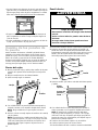
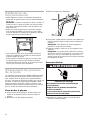
Installing the ice maker
Prepare the ice maker
1. Remove the lower access panel. Take out the screws
securing the grille at the bottom and the one screw from
the center of the front panel support and lift it free of the
cabinet.
2. Turn the fan by hand to make certain it moves freely.
3. Loosen the thumb screws holding the cutter grid and
water pan to “thumb tight,” to make water system cleaning
and sanitizing easier. See the “Removing and cleaning
the interior components” section.
wWARNING
Excessive Weight Hazard
Use two or more people to move and install
ice maker.
Failure to do so can result in back or other injury.
Screw
Screw
Screw
5
ENGLISH

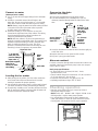
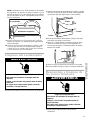
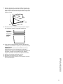
Connect to the drain
(observe local codes)
1. The unit is provided with a gravity-drain system.
2. The ideal installation has a standpipe (1
1
⁄4" [32 cm]
minimum) installed directly below the outlet of the drain
tube.
3. It may be desirable to insulate the drain line thoroughly up
to the drain inlet.
4. Replace the lower access panel and the screws.
5. Plug into 3 prong grounded outlet.
Alternate method:
If a drain connection directly below the drain tube outlet is not
available, install a UL listed drain pump in the rear compart-
ment of the ice maker.
Drain pump specifications:
• UL listed and have a UL listed, 120 VAC, 3-wire,
grounded service cord.
• Overall outside dimensions (maximum): 15" (38 cm) wide x
6" (15 cm) deep x 9
1
⁄2" (24 cm) high.
• Pump flow rate (minimum): 0.4 gpm @ 12 ft. lift.
• Operating temperature range: 55°F to 110°F.
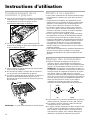
Checking operation
• Start the unit by turning the Cycle Control to ON and
opening the water line valve.
NOTE: Left is OFF – Middle is ON – Right is CLEAN. In the
CLEAN position, only the water pump operates.
• Use a flashlight to look through the space between the
cutter grid and liner to check for even water flow over the
freezing plate. Unit must be level for proper operation.
6
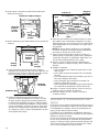
Connect to water
(observe local codes)
1. Use
1
⁄4" (6 mm) OD soft copper tubing for the cold water
supply.
2. Provide a convenient manual shut-off valve in the
water line. Do not use a piercing-type or
3
⁄16-inch saddle
valve which reduces water flow and clogs more easily.
NOTE: Always purge the water line before making the final
connection to the inlet of the water valve to prevent
possible water valve malfunction.
3. Position the tubing so it can enter the access hole
located at the right hand rear of the cabinet. The tubing
should extend beyond the cabinet front when the
cabinet is pushed back into position.
NOTE: After the cabinet is in place, bend the tubing to
meet the connection at the water valve. The garden hose-
threaded compression fitting is found in the parts bag
which is shipped under the ice scoop. This joint
provides a convenient disconnect for servicing. Be sure
the tubing is clear of compressor to prevent rattle.
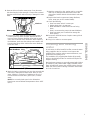
Leveling the ice maker
1. After placing unit in position, check to make certain the
unit is level side-to-side and front-to-back. Accurate
leveling is important for proper operation.
2. Unit should be shimmed so that it is solid as well as level.
The shims should be of hard, permanent-type material.
3. If required by sanitation code, seal the cabinet to the floor
with an approved caulking compound after all water and
electrical connections have been made.
2"
1/
7
/4"
3
/8"
7
23
/4"
3
3
Right End View
3
⁄4" (19 mm)
23
7
⁄8" (606 mm)
3
3
⁄4"
(95 mm)
1
⁄4" (6 mm) OD
water line com-
pression fitting at
water valve
Bend field-supplied
water line to
connect to water
valve fitting
Water
inlet
solenoid
valve
Drain tube
17
/8"
7
9"
/2"
1
1
3"
/2"
1
7
/32"
13
Back View
17
7
⁄8"
(200 mm)
7
1
⁄2"
(190 mm)
9"
(229 mm)
3"
(76 mm)
34
13
⁄32"
(874 mm)
1
1
⁄2"
(38 mm)
Access hole for
field-supplied
water line
4" long
(102 mm)
5
⁄8" ID
(16 mm) rubber
drain tube –
run to open
drain
1
1
⁄4" (32 mm)
minimum
diameter
standpipe
7
1
⁄2"
(190 mm)

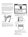
Lower panel
1. Unplug ice maker or disconnect power.
2. Remove the two screws in the lower grille area and the
one screw from the center of the front panel support.
(Open bin door slightly for better access to screw.) Pull
the bottom forward and then pull down to remove the
lower access panel.
3. Remove the screws at each side of the top trim and
remove the top trim.
4. Carefully slide out the decorator panel and reassemble
with selected surface facing out.
NOTE: A custom panel should be
1
⁄4" (6 mm) thick and
17" x 11
15
⁄16" (433 mm x 303 mm). You may need to remove
the metal panels and spacers to allow room for the custom
panel thickness.
5. Replace the top trim and screws.
6. Reinstall the lower access panel.
7. Plug in ice maker or reconnect power.
7
ENGLISH
• Water will not enter the pump pan until the freezing plate
gets cold. Then the machine goes into a harvest cycle.
• Check for desired cube thickness. Adjust after 24 hours if
necessary. Best operation is obtained with ice thickness at
1
⁄2" (13 mm) to
5
⁄8" (16 mm).
Changing the door panels
Both Kenmore models 86485 and 86482 are equipped with
a double-sided decorator panel for both the bin door and the
lower access panel. The decorator panel is white on one side
and black on the other. The Kenmore model 86485 is also
equipped with a single-sided wood grain panel. You can
make custom panels to match your existing cabinet.
Bin door
1. Open the bin door and remove the two screws on the top
of the door. These screws hold the handle in place.
2. Loosen the screws in both side trim pieces.
3. Remove the handle as shown.
4. Carefully slide out the decorator panel and reassemble
with the selected surface facing out.
NOTE: Be careful not to scratch the panel as it is inserted.
5. Replace the handle. Tighten handle and trim piece screws.
NOTE: A custom panel should be
1
⁄4" (6 mm) thick and
17" x 13
3
⁄16" (433 mm x 335 mm). You need to break off the
ribs in the door insulation to allow room for the custom
panel thickness.
Screws
Handle
Screws
(both sides)
wWARNING
Electrical Shock Hazard
Disconnect power before servicing.
Replace all panels before operating.
Failure to do so can result in death or
electrical shock.
Top trim
Front
panel
support
Screw
Screw
Screw

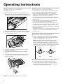
NORMAL
THICK
THIN
ICE
ON
CLEAN
OFF
CYCLE
How the ice maker
makes ice
1. Water constantly circulates over a freezing plate. As the
water freezes into ice, minerals in the water are rejected.
This produces a clear sheet of ice with a low mineral content.
2. When the desired thickness is reached, the ice sheet is
released and slides onto a cutter grid. The grid divides the
sheet into individual cubes.
3. The water containing the rejected minerals is drained
after each freezing cycle.
4. Fresh water enters the unit for the next ice making
cycle.
5. Cubes fall into the storage bin. When the bin is full, the
ice maker shuts off automatically and restarts when
more ice is needed.
NOTE: A normal harvest cycle takes 1 to 2 minutes.
8
Things to remember
• Water enters only during the defrost cycle. Therefore, the
first cycle will be completed without water in the system.
• As the room and water temperatures vary, so will the
amount of ice produced. This means that higher operating
temperatures result in reduced ice production.
• The unit shuts off when ice in the storage bin touches the
bin thermostat. The unit will automatically cycle to keep the
storage bin full.
• The storage bin is not refrigerated and some melting will
occur. This varies with the room temperature.
• The unit needs good air circulation to perform efficiently.
Periodically clean the condenser and grille. If the ice maker
is located on a hard floor surface or there are pets in the
home the condensor should be cleaned every 4-6 weeks for
optimum performance.
• The water system needs to be cleaned periodically for good
circulation. See “Cleaning and sanitizing the ice making
system” section.
Setting the controls
1. Select ice thickness. The ice maker has been preset to
produce ice approximately
1
⁄2" (13 mm) thick, while operat-
ing in a room temperature of 70°F (21°C).
NOTE: Operation in different room temperatures may
require readjusting the Ice Thickness Control toward
THICK or THIN. Best performance is obtained with ice
1
⁄2"
(13 mm) to
5
⁄8" (16 mm) thick. If operating in a warm room
(above 90°F [32°C]), DO NOT set Ice Thickness Control to
the maximum thickness or the unit may malfunction.
2. To start normal ice making cycle, turn Cycle Control to ON.
3. To stop ice making cycle, turn Cycle Control to OFF.
4. The CLEAN setting is used whenever solutions are
circulated through the ice maker for cleaning. Only the
water pump operates at this setting. See “Cleaning and
sanitizing the ice making system” section.
Operating Instructions

Periodically inspect and clean the ice maker to keep it
operating at peak efficiency and to prevent premature failure
of system components.
Both the ice making system and the air-cooled condenser
need to be cleaned regularly. If the ice maker is located on a
hard floor surface or there are pets in the home the
condenser may require cleaning every 4-6 weeks for optimum
performance.
A dirty or clogged condenser prevents proper airflow, reduces
ice making capacity, and causes higher than recommended
operating temperatures which may lead to component failure.
All components of the ice maker are permanently lubricated
at the factory. They should not require any additional oiling
throughout the normal life of the machine.
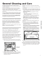
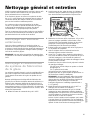
Cleaning exterior surfaces
Wash the exterior enamel cabinet surfaces and gaskets with
warm water and mild soap or detergent. Rinse and dry.
Regular use of a good household-appliance cleaner and
wax will help protect the finish. Treat wood grain panels as
furniture.
NOTE: Do not use harsh or abrasive cleaners on the enamel
surfaces – they may scratch the finish.
Cleaning and sanitizing
the ice making system
The minerals rejected from the circulating water in the freez-
ing cycle will eventually form a hard, scaly deposit in the
water system which prevents the rapid release of ice.
Clean ice making system periodically to remove mineral scale
buildup. Frequency of cleaning depends on water hardness.
With soft water, cleaning may not be required for several
years. With hard water (15 to 20 grains/gal.), cleaning may be
required as often as every 6 months.
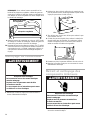
1. Turn Cycle Control to OFF.
2. Open bin door, remove the two thumb screws and slide
the ice cutter grid out of the two slots near the water pan.
3. Unplug the electrical harness. Any ice on the cutter grid
should be melted under running warm water. Attempting
to pick the ice slab from the grid may stretch and
damage the grid wires.
9
ENGLISH
General Cleaning and Care
4. Remove all ice from the storage bin and the freezing
plate.
5. Drain the water pan by removing the drain plug and then
replacing it.
6. Pour
1
⁄2 gallon (1.9 L) of hot tap water into the water pan
and turn the Cycle Control to CLEAN. This warms up the
system to make the cleaning solution more effective. Let
circulate for 5 minutes.
While tap water is circulating, prepare the cleaning
solution. Mix:
6 oz. (170 g) powdered citric or phosphoric acid
1
⁄2 gallon (1.9 L) hot water
(Citric and phosphoric acid crystals are available from
many pharmacies or scientific supply houses.)
NOTE: Commercial Ice Machine cleaners (liquid) are
also available from refrigeration parts supply stores.
Mix according to instructions on label (total quantity =
1
⁄2 gallon [1.9 L]).
7. Turn Cycle Control to OFF and drain tap water. (See
Step 5.)
8. Turn Cycle Control to CLEAN and slowly pour hot
cleaning solution into the water pan. If the solution
foams while pouring, wait until foaming stops. Then
add balance of solution.
Allow solution to circulate until the scale has dissolved
(15 to 30 minutes). Severe scale buildup may require
repeated cleaning with fresh cleaning solution.
NOTE: To clean scale off the freezing plate flanges of
the freezing plate, use rubber gloves and scrub with a
plastic scrubbing pad or non-soapfilled stainless steel
pad dipped in the cleaning solution.
9. Turn Cycle Control to OFF and drain the cleaning solu-
tion. Use rubber gloves when removing the drain plug.
10. Replace the drain plug and add
1
⁄2 gallon (1.9 L) of fresh
water into the water pan. Turn Cycle Control to CLEAN,
let circulate for 5 minutes, and drain. Repeat rinsing
process.
Electrical harness
Thumb screws (long)
Cutter grid
Freezing plate
Freezing plate
flanges

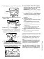
Removing and cleaning the
interior components
1. Unplug ice maker or disconnect power.
2. Remove ice retainer baffle by flexing it to slide it off the
studs.
3. Remove the water pan by unscrewing the two thumb
screws.
10
Insert
into drain
Thumb
screws
(short)
Water pan
Drain
plug
Cleaning the condenser
1. Unplug ice maker or disconnect power.
2. Remove the two screws in the lower grille area and the
one screw from the center of the front panel support.
(Open bin door slightly for better access to the screw.)
3. Pull the bottom forward and then pull down to remove the
lower access panel.
4. Remove dirt and lint from the condenser fins with a soft
brush. Then use a vacuum cleaner with attachments to
remove the dirt from inside the unit compartment.
5. Replace the lower access panel and screws.
6. Plug in ice maker or reconnect power.
wWARNING
Electrical Shock Hazard
Disconnect power before cleaning.
Replace all panels before operating.
Failure to do so can result in death or
electrical shock.
Ice retainer
baffle
Thumb screws (long)
Cutter grid
front trim
wWARNING
Electrical Shock Hazard
Disconnect power before cleaning.
Replace all panels before operating.
Failure to do so can result in death or
electrical shock.
Screw
Screw
Screw

11
ENGLISH
4. Remove the hose from the water pump. Clean the water
inlet hose hanging in the water pan. Scrape off any mineral
deposits and then wash with mild soap or detergent in warm
water.
5. Remove the water distributor from the freezing plate. It
is held in place by rubber endcaps. Remove the inlet
hose and clean all water distributor holes and the small
orifice in the inlet side of the distributor. When replacing
the distributor, make sure the endcaps are located in the
freezing plate flange holes and that the water distributor
holes face down.
6. Wash the interior components you have just removed with
mild soap or detergent and warm water. Rinse in clean
water. Sanitize in a solution of 1 tablespoon (15 ml) of
household bleach mixed with 1 gallon (3.8 L) of warm
water.
NOTE: Do not wash plastic parts in the dishwasher.
Plastic parts cannot withstand temperatures above 145°F
(63°C).
Inlet hose
Water pump
7. Wash the storage bin, door, gasket, and ice scoop with
mild soap or detergent and warm water. Rinse with
clean water. Sanitize with the chlorine bleach and water
solution.
8. Replace the interior components (water distributor,
hoses, water pan, and ice retainer baffle).
9. Check the following:
• Hose from water valve is in water pan.
• Rubber drain plug is in water pan.
• Water distributor is seated and holes are facing
down.
• Hose is reconnected to pump and water distributor.
• Hose from water pan is inserted into storage bin
drain opening.
10. Reconnect electrical harness. Replace cutter grid and
thumb screws.
11. Plug in ice maker or reconnect power.
Filtering and treating
water
In most areas, it will be beneficial to filter or treat the water
being supplied to the ice machine. It can improve the
reliability of the machine, reduce water maintenance, and
produce the best quality of ice.
The installation of a polyphosphate feeder will generally
reduce scale buildup and the ice machine will require less
frequent cleaning.
Municipal water systems are generally treated with chlorine
to maintain a safe, potable water supply. Activated carbon
filters will sufficiently remove the residual chlorine from the
water and reduce surface staining of stainless steel materi-
als in the ice machine.
Freezing plate
holes
Inlet hose
Endcaps
Orifice
Freezing plate
Water distributor

12
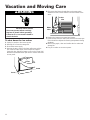
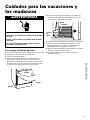
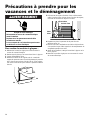
Vacation and Moving Care
To shut down the ice maker:
1. Unplug ice maker or disconnect power.
2. Remove all ice from the storage bin.
3. Shut off the water supply.
4. Remove the two screws in the lower grille area and the
one screw from the center of the front panel support.
(Open bin door slightly for better access to the screw.) Pull
the bottom forward and then pull down to remove the lower
access panel.
wWARNING
Electrical Shock Hazard
Disconnect power before servicing.
Replace all panels before operating.
Failure to do so can result in death or
electrical shock.
Screw
Screw
Screw
5. Disconnect the inlet and outlet lines to the water valve.
Allow these lines to drain and then reconnect them to the
valve.
6. Replace the lower access panel and screws.
7. Remove water from the drain lines and drain the water pan
if the unit will be subjected to freezing temperatures during
shutdown.
8. Before using again, clean and sanitize the ice maker and
storage bin.
9. Plug in ice maker or reconnect power.
Inlet
Outlet
Water
valve

13
ENGLISH
Before Calling for Service
Self-service checklist
Performance problems often result from little things you can
find and fix yourself. Check the list below. It could save you
the cost of a service call.
Unit does not run:
• Cycle Control must be in the ON position.
• Check to see that the power cord is plugged in.
• Check for blown household fuse or tripped circuit breaker.
• Room temperatures must be above 55°F (13°C).
Otherwise, the bin thermostat may sense a cold room
temperature and shut off even though bin is not full of
ice. Also, unit may not restart once it does shut down.
Unit runs but produces no ice:
• Cycle Control must be in the ON position.
• Check water supply to make sure it is open.
• If ice maker is to be operated at an elevation of 2,000 feet
(600 m) or more above sea level, both the Bin Thermostat
and the Ice Thickness Thermostat will need to be
recalibrated. Call your dealer or an authorized service
group to have the necessary changes made.
Unit runs but produces very little ice:
• Room temperature may be extremely high – over 90°F
(32°C). In this case, it is normal for ice production to
be low.
• Dirt or lint may be blocking the airflow through the finned
condenser. Condenser needs to be cleaned.
• Check to see if the unit has a scale buildup in the water
and freezing system. Clean, if necessary.
Cutter grid is not cutting ice sheets:
• Check the grid harness plug to make sure the connection
is secure.
Off-taste in ice cubes:
• There may be an unusually high mineral content in your
water supply. Water may need to be filtered.
• Do not store any foods in the storage bin.
• Make sure all packaging materials have been removed.

14
Notes

Garantía
UN AÑO DE GARANTÍA
COMPLETA
Durante un año a partir de la fecha de compra, si se usa la
fábrica de hielo para fines domésticos, haciéndola funcionar
y manteniéndola de acuerdo con las instrucciones
suministradas o que vienen con ella, Sears reparará la
fábrica de hielo, sin cargo, si tiene defectos de materiales
o de fabricación.
UN AÑO DE GARANTÍA
LIMITADA
Durante un año a partir de la fecha de compra, si se usa la
fábrica de hielo para fines comerciales, haciéndola funcionar
y manteniéndola de acuerdo con las instrucciones
suministradas o que vienen con ella, Sears proveerá, sin
cargo, las piezas de repuesto que tengan defecto de
materiales o de fabricación. Usted pagará la mano de obra.
GARANTÍA COMPLETA DE
CINCO AÑOS PARA EL
SISTEMA DE REFRIGERACIÓN
SELLADO
Durante cinco años a partir de la fecha de compra, siempre
que el funcionamiento y el mantenimiento del producto se
haga de acuerdo con las instrucciones suministradas o que
vienen con el mismo, Sears reparará el sistema sellado (que
consiste en: refrigerante, tuberías de conexión y el motor
compresor), sin cargo, si tuviera defectos de
materiales o de fabricación.
Esta garantía le otorga derechos específicos, y es posible
que usted tenga también otros derechos, los cuales varían
de un estado al otro.
EL SERVICIO DE REPARACIÓN DE LA GARANTÍA ESTÁ
A SU DISPOSICIÓN AL PONERSE EN CONTACTO CON
EL CENTRO DE SERVICIO SEARS O EL ESTABLECIMIEN-
TO SEARS MÁS CERCANO EN LOS ESTADOS UNIDOS.
Sears, Roebuck and Co. • D/817 WA • Hoffman Estates, IL 60179
ANOTE AQUÍ LOS NÚMEROS DE MODELO Y DE SERIE.
Cuando necesite el servicio, o llame para consultar, tenga la
siguiente información a mano:
Número de Modelo
Número de Serie
Fecha de Compra
Centro de Servicio Sears y número de teléfono
15
ESPAÑOL
ÍNDICE
Página
Garantía..........................................................................15
Seguridad de la fábrica de hielo..................................16
Partes y características................................................16
Instrucciones para la instalación ................................17
Requisitos eléctricos.................................................17
Requisitos de espacio...............................................17
Diagramas del cableado de la unidad......................18
Instalación de la fábrica de hielo..............................18
Control del funcionamiento.......................................19
Cambio de los paneles de la puerta.........................20
Instrucciones de funcionamiento................................21
Forma en que la fábrica produce el hielo.................21
Puntos para recordar ...............................................21
Ajuste de los controles..............................................21
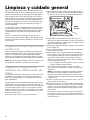
Limpieza y cuidado general.........................................22
Limpieza de las superficies exteriores......................22
Limpieza e higiene del sistema
de elaboración de hielo.............................................22
Limpieza del condensador........................................23
Desmontaje y limpieza de las piezas interiores .......23
Filtrado y tratamiento del agua.................................24
Cuidados para las vacaciones y las mudanzas.........25
Antes de llamar al servicio...........................................26
Números de Sears para llamadas gratuitas...............40

16
Su seguridad y la seguridad de los demás es muy importante.
Hemos incluido muchos mensajes importantes de seguridad en este manual y en su electrodoméstico. Lea
y obedezca siempre todos los mensajes de seguridad.
Este es el símbolo de advertencia de seguridad.
Este símbolo le llama la atención sobre peligros que pueden ocasionar la muerte o una lesión
a usted y a los demás.
Todos los mensajes de seguridad irán precedidos por el símbolo de advertencia de seguridad
y la palabra “PELIGRO” o “ADVERTENCIA”. Estas palabras significan:
Seguridad de la fábrica de hielo
CONSERVE ESTAS INSTRUCCIONES
Si no sigue las instrucciones, usted morirá o sufrirá
una lesión grave.
Si no sigue las instrucciones, usted puede morir o
sufrir una lesión grave.
Todos los mensajes de seguridad identificarán el peligro, le informarán cómo reducir las posibilidades de sufrir una
lesión y lo que puede suceder si no siguen las instrucciones.
wPELIGRO
wADVERTENCIA
INSTRUCCIONES IMPORTANTES DE SEGURIDAD
ADVERTENCIA:
Para reducir el riesgo de incendio, choque eléctrico o lesiones personales al usar la fábrica
de hielo siga estas precauciones básicas:
• Conecte a un contacto de pared de conexión a tierra
de 3 terminales.
• No quite el terminal de conexión a tierra.
• No use un adaptador.
• No use un cable eléctrico de extensión.
• Desconecte el suministro de energía antes de limpiarlo.
• Desconecte el suministro de energía antes de darle
servicio.
• Vuelva a colocar todos los paneles antes de hacer
funcionar.
• Use dos o más personas para mover e instalar la
fábrica de hielo.
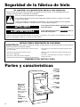
Partes y características
Placa con el
número de
modelo y de
serie
(en la pestaña
interior izquierda
del aparato)
Placa
contenedora
de hielo
Panel de acceso
inferior
Perilla de
control del
ciclo
Perilla de
control del
grosor del
hielo
Cajón del
hielo
Pala para el
hielo

17
ESPAÑOL
Requisitos eléctricos
Requisitos eléctricos
Se requiere un circuito de suministro eléctrico con fusibles de
15 amperios, 115 V, 60 Hz, CA solamente, conectado ade-
cuadamente a tierra de acuerdo con las Normas para
Instalaciones Eléctricas y con las normas y ordenanzas
locales.
Se recomienda tener un circuito separado que sirva sola-
mente para este electrodoméstico. Use un receptáculo que no
pueda ser desconectado con un interruptor o con un conmu-
tador a cadena.
NOTA: Se recomienda el empleo de un fusible retardador
o cortacircuitos.
Método para la conexión a tierra
Para su seguridad personal, este electrodoméstico debe estar
conectado a tierra. Está equipado con un cable eléctrico que
tiene un enchufe de tres terminales con conexión a tierra.
Para reducir el peligro de posibles choques eléctricos, el
cable debe ser enchufado en un contacto de pared que tenga
tres terminales con conexión a tierra, de acuerdo con las
Normas para Instalaciones Eléctricas y con los códigos y
ordenanzas locales. Si no hubiera un contacto adecuado, el
usuario tiene la responsabilidad de contratar a un electricista
calificado para instalar un contacto de pared apropiado que
tenga tres terminales con conexión a tierra.
Contacto de pared
de conexión a tierra
de 3 terminales
Terminal para
conexión a tierra
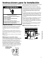
Instrucciones para la instalación
Requisitos de espacio
• Para asegurar la ventilación adecuada de su fábrica de
hielo, la parte del frente debe mantenerse completamente
libre de obstrucciones. La parte superior y los tres lados de
la unidad pueden estar cerrados, pero la instalación debe
ser hecha de manera que la fábrica de hielo pueda ser
movida hacia adelante para hacerle el servicio, si fuera
necesario.
• La instalación de la fábrica de hielo requiere una entrada de
suministro de agua fría con tubos de cobre blando de
1
⁄4 de
pulgada (6 mm) de diámetro exterior y una válvula de cierre,
así como también un sistema de desagüe por gravedad o
una bomba condensadora para llevar el agua a un desagüe
ya existente.
• Elija un área bien ventilada con temperaturas por encima de
los 55°F (13°C) y por debajo de los 110°F (43°C). Los
mejores resultados se logran con temperaturas entre 70°F
(21°C) y 90°F (32°C). Esta unidad DEBE ser instalada en
un área protegida de los elementos tales como el viento, llu-
via, rocío de agua o goteras.
• Cuando instale la fábrica de hielo debajo de un mostrador,
siga las dimensiones de abertura recomendadas que se
muestran a continuación.
NOTA: No deje que el cable eléctrico se tuerza o quede
atrapado entre la fábrica de hielo y el gabinete.
Dimensiones del espacio de empotrado
34
1
⁄2"
(88 cm)
90°
90°
9" máx
(23 cm)
18" (46 cm)
4
1
⁄2" (11.5 cm) A
la línea central
Coloque la
salida dentro
de este
espacio
wADVERTENCIA
Peligro de Choque Eléctrico
Conecte a un contacto de pared de conexión a
tierra de 3 terminales.
No quite el terminal de conexión a tierra.
No use un adaptador.
No use un cable eléctrico de extensión.
No seguir estas instrucciones puede ocasionar
la muerte, incendio o choque eléctrico.

18
Diagramas del cableado de
la unidad
Este modelo funciona con 115V, exceptuando el circuito de la
rejilla de corte que funciona con 8,5V y 1 Amp. El amperaje
máximo del fusible usado debe ser 15 Amp.
El compresor funciona en todo momento exceptuando el
momento en que el termostato lo interrumpe. Esto desactiva
todo el sistema excepto el transformador y la rejilla de corte.
Bajo condiciones normales de funcionamiento, cuando el
evaporador alcanza la temperatura preestablecida (de 10°F
[-12°C] a -3°F [-19°C], dependiendo del espesor del hielo), el
termostato evaporador se abre apagando el motor del
ventilador y el de la bomba. El solenoide de gas caliente y el
solenoide de la válvula de agua permanecen activados en
este momento y permanecen así hasta que el evaporador
alcance los 38°F (3°C).
2
3
CLEAN
OFF
ON
SERVICE
SWITCH
8.5 V
115 V
GRID
TRANSFORMER
COMPRESSOR
START RELAY
OVERLOAD
WATER PUMP
CONDENSER
FAN
115 VOLTS
60 HERTZ
NC
NC
3
2
BIN
THERMOSTAT
EVAPORATOR
THERMOSTAT
L N
R
S
1
1
HOT GAS
6
5
Y
OR
BK
BK
OR
BK
SOL
W
W
W
W
W
W Y
CUTTER
WATER
VALVE
SOL
R
BL
BK / W
BK / W
BK
C
3
2
1
3
2
1
BK / W
Y
BIN
THERMO
EVAP
THERMO
SERVICE
SWITCH
BK/ W
BK
Y
BK
W
W
MOT
PUMP
GRID
BK
W
BL
W
BK
115 V
60 HZ
1 PH
FAN
COMPRESSOR
WATER
HOT GAS
W
SOL
N.C.
SOL
N.C.
OR
W
BK
START
RELAY
OVERLOAD
NL
PLUG
BK
R
115V
TRANS
OROR
G/Y
W
W
BK
G/Y
G
G/Y
CAB
SHELF
CABINET
6
8.5V
CONTROL
BRACKET
MOT
CUADRO DE COLORES
R Rojo
BK Negro
BL Azul
W Blanco
Y Amarillo
OR Naranja
BK/W Trazador de
Negro/Blanco
G/Y Trazador de
Verde/Amarillo
SYMBOL CODE
CONNECTOR - SCREW ON
CONNECTOR - CLOSED END
DISCONNECT TERMINAL
PERMANENT CONNECTION
PLUG CONNECTOR
GROUND (CHASSIS)
=
=
=
=
=
=
w
ADVERTENCIA
Peligro de Choque Eléctrico
Desconecte el suministro de energía antes de darle
servicio.
Vuelva a colocar todos los paneles antes de hacer
funcionar.
No seguir estas instrucciones puede ocasionar
la muerte o choque eléctrico.
= CONECTADOR – PARA ATORNILLAR
= CONECTADOR – EXTREMO CERRADO
= DESCONECTE EL TERMINAL
= CONEXIÓN PERMANENTE
= CONECTADOR DEL ENCHUFE
= TOMA DE TIERRA (CHASIS)
CÓDIGO DE SÍMBOLOS
wADVERTENCIA
Peligro de Peso Excesivo
Use dos o más personas para mover e instalar
la fábrica de hielo.
No seguir esta instrucción puede ocasionar
una herida a la espalda u otra herida.
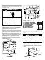
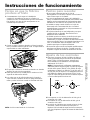
Instalación de la fábrica de
hielo
Preparación de la fábrica de hielo
1. Quite el panel inferior de acceso. Quite los tornillos que
fijan la rejilla a la parte de abajo y un tornillo en el centro
del soporte del panel del frente y levántelo sacándolo del
aparato.
Tornillo
Tornillo
Tornillo

2"
1/
7
3
/4"
3
/8"
7
23
/4"
3
3
Conexión con el desagüe
(cumpla con los códigos locales)
1. La unidad tiene un sistema de desagüe por gravedad.
2. La instalación ideal tiene un tubo de circulación (de 1
1
⁄4
pulgs. [32 cm] como mínimo) puesto directamente por
debajo de la salida del tubo de desagüe.
3. Quizás sea preferible aislar bien la tubería de desagüe
hasta la entrada del drenaje.
4. Vuelva a colocar el panel de acceso inferior y los
tornillos.
5. Enchufe la unidad en un contacto de pared de conexión a
tierra de 3 terminales.
Método alternativo:
Si no se dispone de una conexión de desagüe directamente
ubicada debajo de la salida de la tubería de desagüe,
instale en el compartimiento posterior de la fábrica de hielo
una bomba de desagüe listada en la UL.
Especificaciones para la bomba de desagüe:
• Debe estar listada en la UL y tener un cable de 120 VCA,
de 3 alambres y con conexión a tierra.
•
Las dimensiones exteriores totales (máximas) son: 15 pulgs.
(38 cm) de ancho x 6 pulgs. (15 cm) de profundidad x 9
1
⁄2
pulgs. (24 cm) de altura.
• Gasto de la bomba (mínimo): 0,4 gpm a 12 pies de altura.
• Escala de temperaturas de funcionamiento: 55° F a 110° F.
Control del funcionamiento
• Haga funcionar la unidad poniendo el Control del Ciclo en la
posición “ON” y abriendo la válvula de la tubería de agua.
NOTA: La izquierda es “OFF” (apagado) – la mitad es “ON”
(encendido) y la derecha es “CLEAN” (limpieza). En la posi-
ción “CLEAN” solamente funciona la bomba de agua.
19
ESPAÑOL
17
/8"
7
9"
/2"
1
1
3"
/2"
1
7
/32"
13
34
2. Haga girar a mano el ventilador para asegurarse de que se
mueva libremente.
3. Afloje algo los tornillos de mariposa que sostienen la rejilla
de corte y la bandeja de agua para facilitar la limpieza e
higienización del sistema de agua. Vea la sección
“Desmontaje y limpieza de las piezas interiores”
Conexión del agua
(cumpla con los códigos locales)
1. Utilice tuberías de cobre blando de
1
⁄4 de pulg. (6 mm) de
diámetro exterior para el suministro de agua fría.
2. Ponga en la tubería de agua una válvula de cierre manual
adecuada. No use válvulas perforadoras ni las de tipo de
montura de
3
⁄16 de pulg. porque reducen la corriente de
agua y se atascan con más facilidad.
NOTA: Siempre purgue las tuberías de agua antes de
hacer la conexión final con la válvula de entrada de agua
para prevenir el posible mal funcionamiento de la válvula
de agua.
3. Coloque la tubería de manera que entre en el orificio de
acceso localizado en el lado derecho de la parte trasera
del aparato. Cuando se empuja el aparato hacia atrás para
dejarlo en su posición, la tubería debe sobresalir del frente
del mismo.
NOTA: Luego de poner el aparato en su lugar doble la
tubería para unirla con la conexión en la válvula de agua.
El accesorio de manguera de compresión con rosca se
encuentra en la bolsa de accesorios debajo de la pala de
hielo. Este acoplamiento ofrece un medio conveniente de
desconexión cuando se hace el servicio. Asegúrese de que
la tubería no toque al compresor para evitar ruidos
molestos.
Nivelación de la fábrica de hielo
1. Luego de colocar la unidad en la posición deseada, com-
pruebe que el lado derecho y el izquierdo, el frente y la
parte de atrás estén nivelados. La nivelación precisa es
muy importante para que funcione adecuadamente.
2. La unidad debe estar calzada de manera de que esté firme
y nivelada. Las calzas deben ser de un material duro y
resistente.
3. Si el código de higiene lo requiere, selle el aparato al piso
con un compuesto de enmasillado aprobado, luego de
haber hecho todas las conexiones eléctricas y las de agua.
Vista lateral derecha
3
⁄4" (19 mm)
23
7
⁄8"
(606 mm)
Vista posterior
17
7
⁄8"
(200 mm)
3
3
⁄4"
(95 mm)
7
1
⁄2"
(190 mm)
9"
(229 mm)
3"
(76 mm)
34
13
⁄32"
(874 mm)
7
1
⁄2"
(190 mm)
1
1
⁄2"
(38 mm)
Accesorio de
compresión de la
tubería de agua de
1
⁄4 de pulg. (6 mm)
de diámetro
exterior, en la
válvula de agua.
Doble la tubería
de agua de
suministro local
para conectarla
con el acople
de la válvula de
agua
Válvula
solenoide
de la
entrada
de agua
Orificio de
acceso de la
tubería de agua
de suministro
local.
Tubo de desagüe
de goma al
drenaje abierto,
de 4 pulgs.
(102 mm) de
longitud,
5
⁄8 de
pulg. (16 mm) de
diámetro interior
Tubo de
circulación con
un diámetro
mínimo de 1
1
⁄4
pulgs. (32 mm)
Tubo de
desagüe
continúa en la página siguiente

Panel inferior
1. Desenchufe la fábrica de hielo o desconecte la electricidad.
2. Quite los dos tornillos del área inferior de la rejilla y el
tornillo del centro del soporte del panel del frente. (Abra
ligeramente la puerta del cajón para lograr mejor acceso al
tornillo.) Tire de la parte inferior hacia adelante y luego
hacia abajo para quitar el panel de acceso inferior.
3. Quite los tornillos que están a cada lado del ribete superior
y quítelo.
4. Con cuidado deslice el panel decorativo para quitarlo y
vuelva a montarlo con la superficie elegida hacia afuera.
NOTA: El panel hecho a pedido especial debe tener
1
⁄4 de pulg. (6 mm) de espesor y 17 pulgs. x 11
15
⁄16 pulgs.
(433 mm x 303 mm). Es posible que tenga que quitar los
paneles de metal y los espaciadores para dejarle lugar al
panel hecho a pedido especial.
5. Vuelva a colocar el ribete superior con los tornillos.
6. Vuelva a instalar el panel de acceso inferior.
7. Enchufe la fábrica de hielo o vuelva a conectar la electricidad.
w
ADVERTENCIA
Peligro de Choque Eléctrico
Desconecte el suministro de energía antes de darle
servicio.
Vuelva a colocar todos los paneles antes de hacer
funcionar.
No seguir estas instrucciones puede ocasionar
la muerte o choque eléctrico.
Ribete
superior
Soporte del
panel del
frente
20
• Use una linterna para observar el espacio que está entre la
rejilla de corte y el revestimiento para controlar que haya un
flujo de agua parejo sobre la placa congeladora. La unidad
debe estar nivelada para que funcione adecuadamente.
• El agua no entrará a la bandeja de la bomba hasta que la
placa congeladora se enfríe. Luego la máquina ingresa al
ciclo de cosecha.
• El mejor rendimiento se obtiene con un espesor de hielo de
1
⁄2 pulg. (13 mm) hasta
5
⁄8 de pulg. (16 mm).
Cambio de los paneles de
la puerta
Ambos modelos de Kenmore, el 86485 y el 86482 vienen
equipados con paneles decorativos de dos frentes para la
puerta del cajón y el acceso inferior. El panel decorativo es
blanco de un lado y negro del otro. El modelo 86485 de
Kenmore está también equipado con un panel de madera de
un lado. Usted puede adquirir también paneles hechos por
encargo para que hagan juego con los demás muebles.
Puerta del cajón
1. Abra la puerta del cajón y quite los dos tornillos de la parte
superior de la puerta. Estos tornillos fijan la manija de la
puerta.
2. Afloje los tornillos de los dos ribetes laterales.
3. Quite la manija según se muestra.
4. Con cuidado deslice el panel decorativo hasta quitarlo y
vuélvalo a montar con la superficie elegida hacia afuera.
NOTA: Tenga cuidado de no rayar el panel cuando lo
inserte.
5. Vuelva a colocar la manija. Apriete los tornillos de la manija
y de los ribetes.
NOTA: El panel hecho a pedido especial debe tener
1
⁄4 de
pulg. (6 mm) de espesor y 17 pulg. x 13
3
⁄16 pulgs. (433 mm
x 335 mm). Debe quitar las varillas de la aislación de la
puerta para darle lugar al espesor del panel hecho a
pedido especial.
Tornillo
Tornillo
Tornillo
Tornillos
Manija
Tornillos
(en los
dos lados)
La page est en cours de chargement...
La page est en cours de chargement...
La page est en cours de chargement...
La page est en cours de chargement...
La page est en cours de chargement...
La page est en cours de chargement...
La page est en cours de chargement...
La page est en cours de chargement...
La page est en cours de chargement...
La page est en cours de chargement...
La page est en cours de chargement...
La page est en cours de chargement...
La page est en cours de chargement...
La page est en cours de chargement...
La page est en cours de chargement...
La page est en cours de chargement...
La page est en cours de chargement...
La page est en cours de chargement...
La page est en cours de chargement...
La page est en cours de chargement...
-
 1
1
-
 2
2
-
 3
3
-
 4
4
-
 5
5
-
 6
6
-
 7
7
-
 8
8
-
 9
9
-
 10
10
-
 11
11
-
 12
12
-
 13
13
-
 14
14
-
 15
15
-
 16
16
-
 17
17
-
 18
18
-
 19
19
-
 20
20
-
 21
21
-
 22
22
-
 23
23
-
 24
24
-
 25
25
-
 26
26
-
 27
27
-
 28
28
-
 29
29
-
 30
30
-
 31
31
-
 32
32
-
 33
33
-
 34
34
-
 35
35
-
 36
36
-
 37
37
-
 38
38
-
 39
39
-
 40
40


Kenmore 86482 Manuel utilisateur
- Taper
- Manuel utilisateur
- Ce manuel convient également à
dans d''autres langues
- English: Kenmore 86482 User manual
- español: Kenmore 86482 Manual de usuario
Documents connexes
-
Kenmore 10689483995 Le manuel du propriétaire
-
-
-
-
-
-
-
-
-