ROSIERES RDG9DCK3B-ALG/1 Manuel utilisateur
- Catégorie
- Ventilateurs ménagers
- Taper
- Manuel utilisateur
Ce manuel convient également à

لﯾﻟد مدﺧﺗﺳﻣﻟاو بﯾﻛرﺗﻟا
ENGLISH INSTALLATION AND USER’S MANUAL
FRENCH NOTICE D’INSTALLATION ET D’UTILISATION

30
INSTALLATION AND USER’S MANUAL
CONTENT
INTRODUCTION
2
SAFETY PRECAUTION
2
SPECIFICATION
5
INSTALLATION (VENT OUTSIDE)
6
INSTALLATION (VENT INSIDE)
17
DESCRIPTION OF COMPONENTS
18
OPERATION
18
MAINTENANCE
22
TROBULESHOOTING
23
CONFORMITY WITH DIRECTIVES
23
ENVIRONMENTAL PROTECTION
24
1

31
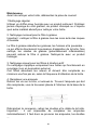
INTRODUCTION
Thank you for choosing this cooker hood.
This instruction manual is designed to provide you with all required
instructions related to the installation, use and maintenance of the appliance.
In order to operate the unit correctly and safety, please read this instruction
manual carefully before installation and usage.
The cooker hood uses high quality materials, and is made with a streamlined
design. Equipped with large power electric motor and centrifugal fan, it also
provides strong suction power, low noise operation, non-stick grease filter and
easy assembly installation.
SAFETY PRECAUTION
Never let the children operate the machine.
The cooker hood is for home use only, not suitable for barbecue, roast
shop and other commercial purpose.
The cooker hood and its filter should be clean regularly in order to
keep in good working condition.
Clean the cooker hood according to the instruction manual and keep
the unit from danger of burning.
Forbid the direct baking from the gas cooker.
Please keep the kitchen room a good convection.
Before connecting this appliance check that the power supply cord is
not damaged. A damage supply cord must be replaced by qualified
service personnel only.
There shall be adequate ventilation of the room when the range hood
is used at the same time as appliances burning gas or other fuels;
he air must not be discharged into a flue that is used for
exhausting fumes from appliances burning gas or other fuels;
Regulations concerning the discharge of air have to be fulfilled.
This appliance if not intended for use by persons(including children)
with reduced physical, sensory or mental capabilities, or lack of
experience and knowledge, unless they have been given supervision
or instruction concerning use of the appliance by a person slide for
their safety.
Children should be supervised to ensure that they do not play with the
appliance.
2

32
Do not flambé under the range hood.
CAUTION: Accessible parts may become hot when used with cooking
appliance
Electrical Shock Hazard
Only plug this unit into a properly earthed outlet. If in doubt seek
advice from a suitably qualified engineer.
Failure to follow these instructions can result in death, fire, or
electrical shock.
- These shall be adequate ventilation of the room when the
range hood is used at the same time as appliances burning
gas or other fuels(not applicable to appliances that only
discharge the air back into the room);
- the details concerning the method and frequency of cleaning.
- there is a fire risk if cleaning is not carried out in accordance
with the instructions; - do not flame under the range hood;
- CAUTION:Accessible parts may become hot when used with
cooking appliances.
3

32
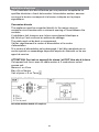
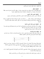
Direct Connection
The appliance must be connected directly to the mains using an
omnipolar circuit breaker with a minimum opening of 3mm between
the contacts.
The installer must ensure that the correct electrical connection has
been made and that it complies with the wiring diagram.
The cable must not be bent or compressed.
Regularly check the power plug and power cord for damage. If the
supply cord is damaged, it must be replaced by a special cord or
assembly available from the manufacturer or its service agent.
WARNING: This is a Class I appliance and MUST be earthed
This appliance is supplied with a 3 core mains cable coloured as
follows:
Brown = L or Live
Blue = N or Neutral
Green and Yellow = E or Earth
The fuse must be rated at 3 Amps.
Electrical Installation
All installation must be carried out by a competent person or qualified
electrician. Before connecting the mains supply ensure that the mains
voltage corresponds to the voltage on the rating plate.
4

33
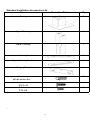
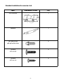
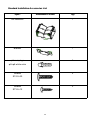
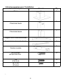
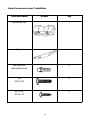
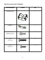
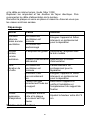
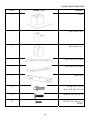
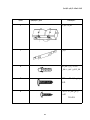
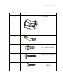
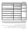
Standard Installation Accessories List
Spec.
Illustration Picture
Qty
Casing
1
Upper Chimney
1
Lower Chimney
1
Lower chimney bracket
1
Upper chimney bracket
1
Hanging Board
1
φ8 rawl plugs
φ8×φ6 white color
9
Screws
ST4.0×30
9
φ7.2screws
ST4.0×8
2
5

34
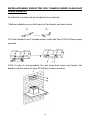
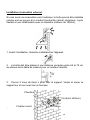
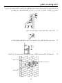
INSTALLATION
(
wall mounting
)
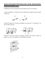
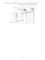
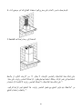
If you have an outlet to the outside, your cooker hood can be connected as
below picture by means of an extraction duct (enamel, aluminum, flexible pipe or
inflammable material with an interior diameter of 150mm)
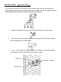
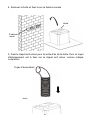
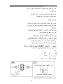
1. Before installation, turn the unit off and unplug it from the outlet.
2. The cooker hood should be placed at a distance of 65~75cm above
the cooking plane for best effect.
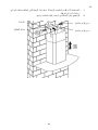
3. Drill 3 x 8mm holes to accommodate the bracket. Screw and tighten
the bracket onto the wall with the screws provided.
Wall plug
Wall bracket
107.5mm
Screw(4mm x 30mm)
6

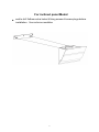
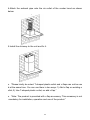
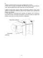
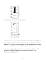
eed to drill 2x8mm extra holes & fixing screws & screw plugs before
installation. Voor schuine modellen
For inclined panel Model
7

35
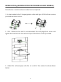
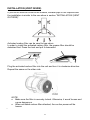
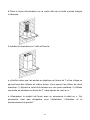
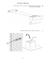
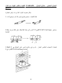
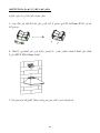
4. Leave up the cooker hood and hang onto the wall bracket hook.
Cooker hook
Wall
bracket
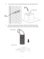
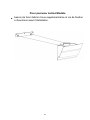
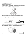
5. Fix the one-way-valve to the air outlet of the cooker hood. Then,
attached the exhaust pipe onto the one-way-valve as shown below.
Exhaust pipe
Cooker hood
8

36
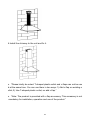
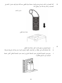
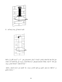
6.
i. Place the glass in appropriate position on the top the cooker
hood.
ii. Fix with 4 screws and washer. In order to avoid the glass
cracking, please do not tighten the screws too strongly.
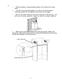
i. By Put the inner chimney into outer chimney .Then pulling out
the inner chimney upwards. Adjust to reach the height required.
ii. Sliding the chimney to adjust the chimney height. When the
height you required is reached, then hang the fixing hole to the fixing
screws as showed in below pictures.
Inner chimney
Outer chimney
9

37
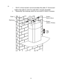
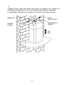
8.
i. Drill 2 x 8mm holes to accommodate the plate II. Screw and
tighten the plate II onto the wall with 2 screws provided.
ii. Assembly the chimney onto the unit and fix it with 2 screws.
Plate II
Wall plug
Screw
4mm x 8mm
Screw
(4mm x 30mm)
10

Standard Installation Accessories List
Spec. Illustration Picture Qty
Air Deflector 1
Bracket 1
φ8 rawl plugs
φ8×φ6whitecolor
2
Screws
ST4.0×30
2
Screws
ST3.5×12
2
11

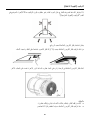
INSTALLATION(AIR DEFLECTOR FOR T-SHAPE,CURVED GLASS,FLAT
GLASS MODELS):
Air deflector is mentioned as included and not optional.
1.Before installation,curve both ends of the bracket as shown below:
2.Fix the bracket to the T-shaped plastic outlet with 2pcs ST3.5x12mm screws
provided.
3.Drill 2 holes to accommodate the wall plugs,then screw and tighten the
bracket onto the wall with 2pcs ST4x30mm screws provided.
12

4.Attach the exhaust pipe onto the air outlet of the cooker hood as shown
below:
5.Install the chimney to the unit and fix it.
o “Please kindly be noted: T-shaped plastic outlet and v-flaps can not be use
datthesametime.Youcanusethemintwoways:1)Addv-flaponexistingo
utlet; 2) Use T-shaped plastic outlet, no add v-flap.”
o “Note: The product is provided with v-flap accessory. This accessory is not
mandatory for installation, operation and use of the product.”
13

Standard Installation Accessories List
Spec. Illustration Picture Qty
Air Deflector 1
Bracket 1
φ8rawlplugs
φ8×φ6whitecolor
2
Screws
ST4.0×30
2
Screws
ST3.5×12
2
14

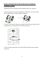
INSTALLATION(AIR DEFLECTOR FOR PYRAMID & SLANT MODELS):
Air deflector is mentioned as included and not optional.
1.Fix the bracket to the T-shaped plastic outlet with 2pcs ST3.5x12mm screws
provided as shown below:
2. Drill 2 holes on the wall to accommodate the wall plugs,then screw and
tighten the bracket onto the wall with 2pcs ST4x30mm screws provided.
3. Attach the exhaust pipe onto the air outlet of the cooker hood as shown
below:
15

4.Install the chimney to the unit and fix it.
o “Please kindly be noted: T-shaped plastic outlet and v-flaps can not be use
datthesametime.Youcanusethemintwoways:1)Addv-flaponexistingo
utlet; 2) Use T-shaped plastic outlet, no add v-flap.”
o “Note: The product is provided with v-flap accessory. This accessory is not
mandatory for installation, operation and use of the product.”
16

38
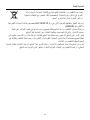
INSTALLATION (VENT INSIDE)
If you do not have an outlet to the outside, exhaust pipe is not required and
the installation is similar to the one show in section “INSTALLATION (VENT
OUTSIDE)”.
Activated carbon filter can be used to trap odors.
In order to install the activated carbon filter, the grease filter should be
detached first. Press the lock and pull it downward.
Plug the activated carbon filter into the unit and turn it in clockwise direction.
Repeat the same on the other side.
NOTE:
oMake sure the filter is securely locked. Otherwise, it would loosen and
cause dangerous.
oWhen activated carbon filter attached, the suction power will be
lowere
17

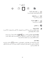
DESCRIPTION OF COMPONENTS
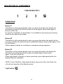
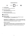
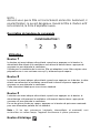
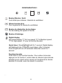
OPERATION
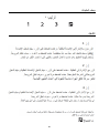
Button 1
The button is with indicate backlit, when you press the button,the backlit will
be turned on and the fan will be turned on at low speed. when press again, it
will turn off the fan.
It’s used for Ventilation on the kitchen. It is suitable for simmering and cooking
which do not make much steam.
Button 2
The button is with indicate backlit, when you press the button,the backlit will be
turned on and the fan will be turned on at Medium Speed. when press again, it will
turn off the fan.
Airflow speed is ideally for ventilation in standard cooking operation.
Button 3
The button is with indicate backlit, when you press the button,the backlit will
be turned on and the fan will be turned on at High Speed. when press
again,. it will turn off the fan.
When high density of smoke or steam produced, press high-speed button for
highest effective ventilation.
Light button
CONFIGURATION 1
NOTE: If Low / Medium / High speed buttons are press at the same time, the
unit will only operate at the highest speed.
18

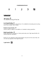
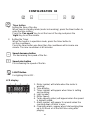
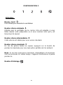
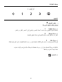
OPERATION
Low Speed button 1
It’s used for Ventilation on the kitchen. It is suitable for simmering and cooking
which do not make much steam.
Medium Speed button 2
Airflow speed is ideally for ventilation in standard cooking operation.
High Speed button 3
When high density of smoke or steam produced, press high-speed button for
highest effective ventilation.
Light button
NOTE: If Low / Medium / High speed buttons are press at the same time, the
unit will only operate at the highest speed.
Off button
It’s used for turning off the fan.
CONFIGURATION 2
19
La page charge ...
La page charge ...
La page charge ...
La page charge ...
La page charge ...
La page charge ...
La page charge ...
La page charge ...
La page charge ...
La page charge ...
La page charge ...
La page charge ...
La page charge ...
La page charge ...
La page charge ...
La page charge ...
La page charge ...
La page charge ...
La page charge ...
La page charge ...
La page charge ...
La page charge ...
La page charge ...
La page charge ...
La page charge ...
La page charge ...
La page charge ...
La page charge ...
La page charge ...
La page charge ...
La page charge ...
La page charge ...
La page charge ...
La page charge ...
La page charge ...
La page charge ...
La page charge ...
La page charge ...
La page charge ...
La page charge ...
La page charge ...
La page charge ...
La page charge ...
La page charge ...
La page charge ...
La page charge ...
La page charge ...
La page charge ...
La page charge ...
La page charge ...
La page charge ...
La page charge ...
La page charge ...
La page charge ...
-
 1
1
-
 2
2
-
 3
3
-
 4
4
-
 5
5
-
 6
6
-
 7
7
-
 8
8
-
 9
9
-
 10
10
-
 11
11
-
 12
12
-
 13
13
-
 14
14
-
 15
15
-
 16
16
-
 17
17
-
 18
18
-
 19
19
-
 20
20
-
 21
21
-
 22
22
-
 23
23
-
 24
24
-
 25
25
-
 26
26
-
 27
27
-
 28
28
-
 29
29
-
 30
30
-
 31
31
-
 32
32
-
 33
33
-
 34
34
-
 35
35
-
 36
36
-
 37
37
-
 38
38
-
 39
39
-
 40
40
-
 41
41
-
 42
42
-
 43
43
-
 44
44
-
 45
45
-
 46
46
-
 47
47
-
 48
48
-
 49
49
-
 50
50
-
 51
51
-
 52
52
-
 53
53
-
 54
54
-
 55
55
-
 56
56
-
 57
57
-
 58
58
-
 59
59
-
 60
60
-
 61
61
-
 62
62
-
 63
63
-
 64
64
-
 65
65
-
 66
66
-
 67
67
-
 68
68
-
 69
69
-
 70
70
-
 71
71
-
 72
72
-
 73
73
-
 74
74


ROSIERES RDG9DCK3B-ALG/1 Manuel utilisateur
- Catégorie
- Ventilateurs ménagers
- Taper
- Manuel utilisateur
- Ce manuel convient également à
dans d''autres langues
- English: ROSIERES RDG9DCK3B-ALG/1 User manual
Documents connexes
-
ROSIERES RDG9DCK3B-ALG/1 Manuel utilisateur
-
-
-
-
-
-
-