
Solar and High-Performance
DHW Storage Tanks
SM80/5, SM100/5
6 720 647 567-00.1ITL
[en] Installation and Service Instructions - Read carefully prior to installation and maintenance.. . . . . . . . . . . . . . . . . . . . . . . . . . . . . 2
[fr] Notice d’installation et d’entretien - À lire attentivement avant le montage et la maintenance. . . . . . . . . . . . . . . . . . . . . . . . . . . . 19
[es] Instrucciones de mantenimiento y de instalación -
Léase atentamente antes del montaje o de la realización de trabajos de mantenimiento. . . . . . . . . . . . . . . . . . . . . . . . . . . . . . . . 37
6 720 800 156 (2017/07) US/CA/MX
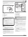
WARNING:
These installation instructions are intended solely for use by a licensed
heating contractor or service technician. Read all instructions before in-
stalling. Perform steps exactly in the order given. Failure to follow these
instructions can result in severe injury, death or property damage.
NOTICE:
The heat transfer medium must be nontoxic water with Toxicity Class 1
as listed in "Clinical Toxicology of Commercial Products," 5th edition.
The heat transfer medium must be limited to a maximum pressure of
30 PSIG by an approved safety or pressure relief valve.
DANGER :
Cette notice d’installation doit être utilisée uniquement par des installa-
teurs chauffagistes ou des techniciens de maintenance qualifiés. Lisez
attentivement toutes les consignes avant l’installation. Exécutez les ac-
tions précisément dans l’ordre indiqué. En cas de non-respect, vous ris-
quez de subir de sérieuses blessures pouvant conduire à la mort ou
d’entraîner de lourds dommages matériels.
REMARQUE :
Le milieu caloporteur doit être de l’eau non toxique de classe 1 telle que
précisé dans la 5e édition de « Clinical Toxicology of Commercial
Products ». Le liquide caloporteur doit être limité à une pression maximale
de 30 PSIG par une soupape de sécurité ou de surpression homologuée.
PELIGRO :
Este manual de instalación únicamente lo pueden utilizar instaladores de
calefacción o técnicos especializados. Antes de la instalación, lea todas
las indicaciones. Realice todas las acciones exactamente en el orden in-
dicado. En caso de incumplimiento, existe riesgo de lesiones graves e in-
cluso de muerte o daños materiales considerables.
AVISO :
El portador de calor se debe limitar a una presión máxima de 2 bar me-
diante una válvula de seguridad o de sobrepresión.

Contents
SM80/5, SM100/5 – 6 720 800 156 (2017/07)2
Contents
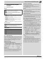
1 Safety Considerations and Symbol Descriptions . . . . . . . . . . 3
1.1 Explanation of symbols . . . . . . . . . . . . . . . . . . . . . . . . . . 3
1.2 Safety instructions . . . . . . . . . . . . . . . . . . . . . . . . . . . . . . 3
1.3 Instructions for the owner and operator . . . . . . . . . . . . . 4
2 Product Information . . . . . . . . . . . . . . . . . . . . . . . . . . . . . . . . . . . 4
2.1 Scope of delivery . . . . . . . . . . . . . . . . . . . . . . . . . . . . . . . 4
2.2 Designated use . . . . . . . . . . . . . . . . . . . . . . . . . . . . . . . . . 5
2.3 Product Information . . . . . . . . . . . . . . . . . . . . . . . . . . . . . 5
2.4 Data plate . . . . . . . . . . . . . . . . . . . . . . . . . . . . . . . . . . . . . 5
2.5 Pressure drop curve of heating coil . . . . . . . . . . . . . . . . . 6
2.6 Technical Data . . . . . . . . . . . . . . . . . . . . . . . . . . . . . . . . . 7
2.7 Physical and connection dimensions . . . . . . . . . . . . . . . 8
3 Standards, regulations and directives . . . . . . . . . . . . . . . . . . . 9
4 Moving the tank . . . . . . . . . . . . . . . . . . . . . . . . . . . . . . . . . . . . . . 9
5 Installation . . . . . . . . . . . . . . . . . . . . . . . . . . . . . . . . . . . . . . . . . . . 9
5.1 Tank installation . . . . . . . . . . . . . . . . . . . . . . . . . . . . . . . . 9
5.1.1 Requirements for installation location . . . . . . . . . . . . . . 9
5.1.2 Wall clearances . . . . . . . . . . . . . . . . . . . . . . . . . . . . . . . . 10
5.1.3 Positioning the tank . . . . . . . . . . . . . . . . . . . . . . . . . . . . 10
5.2 Water connections . . . . . . . . . . . . . . . . . . . . . . . . . . . . . 11
5.2.1 Connecting the tank on the water side . . . . . . . . . . . . . 12
5.2.2 Installing a T&P safety valve (on-site) . . . . . . . . . . . . . . 12
5.3 Installing the DHW water temperature sensor
(accessory) or Aquastat (accessory) . . . . . . . . . . . . . . 12
5.4 Connecting the KS solar pump station . . . . . . . . . . . . . 14
5.5 Connection as high-performance DHW tank . . . . . . . . . 14
5.5.1 Series connection of the lower and upper heat
exchanger . . . . . . . . . . . . . . . . . . . . . . . . . . . . . . . . . . . 14
5.5.2 Parallel connection of the lower and upper heat
exchanger . . . . . . . . . . . . . . . . . . . . . . . . . . . . . . . . . . . . 15
6 Start-up procedure . . . . . . . . . . . . . . . . . . . . . . . . . . . . . . . . . . . 15
6.1 Commissioning the DHW tank . . . . . . . . . . . . . . . . . . . . 15
7 Shutdown . . . . . . . . . . . . . . . . . . . . . . . . . . . . . . . . . . . . . . . . . . . 15
7.1 Shutting down the tank . . . . . . . . . . . . . . . . . . . . . . . . . 15
7.2 Shutting down the heating system when there is a risk
of frost . . . . . . . . . . . . . . . . . . . . . . . . . . . . . . . . . . . . . . 15
8 Environmental protection/disposal . . . . . . . . . . . . . . . . . . . . . 15
9 Maintenance . . . . . . . . . . . . . . . . . . . . . . . . . . . . . . . . . . . . . . . 15
9.1 Preparing the DHW tank for cleaning . . . . . . . . . . . . . . 15
9.2 Descaling/cleaning the tank . . . . . . . . . . . . . . . . . . . . . 16
9.3 Check the magnesium anodes . . . . . . . . . . . . . . . . . . . . 16
9.4 Startup after maintenance . . . . . . . . . . . . . . . . . . . . . . . 17
10 Spare Parts . . . . . . . . . . . . . . . . . . . . . . . . . . . . . . . . . . . . . . . . . 18
10.1 Spare parts for SM80/5, SM100/5 . . . . . . . . . . . . . . . 18

1
Safety Considerations and Symbol Descriptions
SM80/5, SM100/5 – 6 720 800 156 (2017/07) 3
1 Safety Considerations and Symbol
Descriptions
1.1 Explanation of symbols
Warnings
The following keywords are defined and can be used in this document:
• DANGER indicates a hazardous situation which, if not avoided, will
result in death or serious injury.
• WARNING indicates a hazardous situation which, if not avoided,
could result in death or serious injury.
• CAUTION indicates a hazardous situation which, if not avoided,
could result in minor to moderate injury.
• NOTICE is used to address practices not related to personal injury.
Important Information
Additional symbols
1.2 Safety instructions
Read all instructions before installing. Perform the steps in the indicated
sequence. Have the DHW tank inspected by a trained service technician
at least once every year. Failure to comply with these instructions can
result in severe, possibly fatal, personal injury as well as damage to
property and equipment.
Installation and servicing
▶ Risk of fire from soldering and brazing!
Take appropriate protective measures when soldering and brazing as
the insulation is flammable, for example, cover the insulation.
▶ Ensure that only a licensed contractor installs or services the DHW
tank.
▶ Use installation material with adequate temperature stability.
Forbidden:
Connection of the potentiostat for an impressed current anode to the
magnesium anode installed in a storage tank is absolutely forbidden!
This would destroy the tank! The warranty would be voided.
Installation and commissioning
▶ The electrical connection must be connected by a electrician.
The wiring diagram must be followed.
▶ Do not install this device in rooms with a high moisture level
(e.g. bathrooms, saunas).
Function
▶ To ensure that the tank functions properly, heed these installation
and maintenance instructions.
▶ Never close the blow-off line of the T&P safety valve. For safety
reasons, water may escape during heating.
Danger from electric shock
▶ Make sure that only certified electricians perform the electrical work.
▶ Before performing electrical work, disconnect the power and secure
the unit against unintentional reconnection.
▶ Ensure the system has been disconnected from the power supply.
Risk of scalding at the hot water draw-off point
▶ When the DHW tank is in operation, temperatures in excess of 122 °F
(50 °C) can occur. To limit the temperature at the tap, install a
thermostatic DHW mixing valve.
▶ Water heated for washing the laundry, dishes and for other cleaning
purposes can cause scalding and permanent injuries.
▶ Children, elderly, and handicapped persons are more likely to be
permanently injured by hot water. Never leave such individuals in the
tub or shower unattended under any circumstances. Children must
not be allowed to operate hot water faucets themselves or to fill a
bathtub.
▶ If the building has occupants in the above groups who operate hot
water faucets, or state laws / local ordinances stipulate specific
water temperatures, take the following precautions:
– Use the lowest possible temperature setting.
– To prevent scalding, install a tempering device, such as an
automatic mixing valve, at hot water tap or water heater. Select
and install the automatic mixing valve in accordance with the
valve manufacturer's recommendations and instructions.
▶ Water exiting from drain valves can be extremely hot. To avoid
injuries:
– Check that all connections are tight.
– Direct exiting water away from people.
▶ Measures must be taken to protect against excessive temperature
and pressure! Installation of a T&P safety valve is required.
The chart below shows the relationship between water temperature and
time until there is a risk of scalding. It can be used as the basis for
determining the safest water temperature for your application.
Warnings in this document are identified by a warning
triangle printed against a grey background.
Keywords at the start of a warning indicate the type and
seriousness of the ensuing risk if measures to prevent
the risk are not taken.
This symbol indicates important information where
there is no risk to people or property. It is separated by
horizontal lines above and below the text.
Symbol Function
▶ Sequence of steps
Cross-reference to another part of the document
• Listing/list entry
– Listing/list entry (2nd level)
Table 1

2
Product Information
SM80/5, SM100/5 – 6 720 800 156 (2017/07)4
To protect against corrosion and ensure compliance with the rules for
electrical safety, observe the following points:
▶ Use metal fittings for drinking water heating systems with plastic
piping.
▶ Use only original accessories from the manufacturer.
▶ When installation of the tank is complete, inspect the ground
conductor (including metal fittings).
Maintenance
Customers are advised to:
▶ Sign a maintenance and inspection contract with an authorized
contractor. Inspect and maintain the DHW tank as necessary on a
yearly basis. Service as needed.
▶ Use only original spare parts.
Flooding
▶ After a flood, do not use the appliance if any part has been
submerged. Damage to appliances that have been submerged can be
quite severe and pose numerous safety risks.
▶ An appliance that was subject to flooding must be replaced.
1.3 Instructions for the owner and operator
▶ Explain the operation and handling of the heating system and DHW
tank, making a particular point of safety-relevant features.
▶ Explain the function and how to check the T&P safety valve.
▶ Hand all enclosed documents over to the owner/operator.
▶ Recommendation for the user: Sign a maintenance and inspection
contract with a licensed contractor.
▶ Highlight the following for the user:
– Water may be discharged from the T&P safety valve during heat-
up.
– The blow-off line on the T&P safety valve must always be kept
open.
– Check that the T&P safety valve operates properly at least once
yearly.
– The tank must be inspected annually and maintained as required.
2 Product Information
2.1 Scope of delivery
• DHW tanks
•Tank components
• Installation and Maintenance Instructions
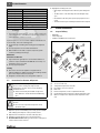
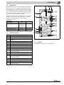
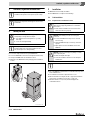
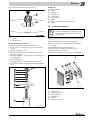
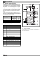
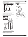
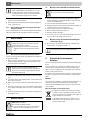
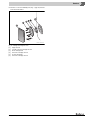
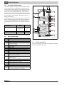
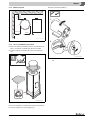
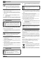
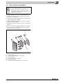
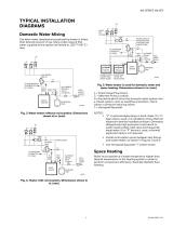
Fig. 1 Tank components
[1] Tee 1" x 1" x 3/4" (2x)
[2] Temperature and pressure relief valve
[3] Recirculation connection cap 3/4"
[4] Drain valve
[5] Bracket for aquastat, screws for aquastat bracket (4x)
[6] Compensating spring for aquastat or cylinder temperature sensor
[7] Quarter-circle spacers for aquastat or tank temperature sensor
(2x)
Temperature Time to severe scalding
120 °F (48 °C) longer than 5 minutes
125 °F (51 °C) 1.5 to 2 minutes
130 °F (54 °C) approx. 30 seconds
135 °F (57 °C) approx. 10 seconds
140 °F (60 °C) less than 5 seconds
145 °F (62 °C) less than 3 seconds
150 °F (65 °C) approx. 1.5 seconds
155 °F (68 °C) approx. 1 second
Table 2 Approximate time-temperature relationship until there is a risk
of scalding
1
1. Source: Moritz, A.R. and Henriques, F.C., Jr. (1947). Studies of thermal injury.
II. The relative importance of time and surface temperature in the causation of
cutaneous burns, Am J of Pathol, 23, 695-720.
WARNING: Risk of scalding at the taps!
There is a risk of scalding at the taps if the tank
temperature is set above 122 °F (50 °C) and during
thermal disinfection.
▶ Advise users that they should draw off only mixed
water. Otherwise, install a thermostatic DHW mixing
valve.
NOTICE: Risk of tank damage from excessively high
pressure.
▶ Never close the temperature and pressure safety
valve blow-off line.
6 720 805 397-01.1ITL
1
2
4
3
5
7
6

2
Product Information
SM80/5, SM100/5 – 6 720 800 156 (2017/07) 5
2.2 Designated use
The DHW tank can be operated in a solar thermal system with a boiler as
a back-up, or for high output only with a boiler. (Operation of the two
heat exchangers in series or parallel.) The tank is designed for heating
and storing drinking water. Please observe national, regional, and local
codes, regulations, guidelines and standards for drinking water. When
operated as part of a solar system, the solar thermal system must be
filled with solar antifreeze to prevent frost damage.
The tank can be used only in closed loop systems and is not suitable for
drain-back solar thermal systems. Any other purpose is considered
improper use. Any resulting damage is excluded from the
manufacturer's warranty.
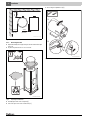
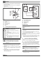
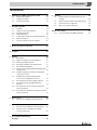
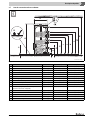
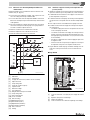
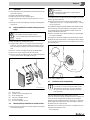
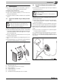
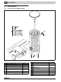
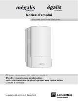
2.3 Product Information
Fig. 2 SM80/5, SM100/5
2.4 Data plate
The data plate is located at the top rear of the DHW tank.
Requirements
for potable water Unit
Water hardness, min. ppm
grain/US gallon
°dH
36
2.1
2
pH value, min. – max. 6.5 – 9.5
Conductivity, min. – max. μS/cm 130 – 1500
Table 3 Requirements for potable water
Item Description
1 DHW outlet
2 Boiler supply
3 Sensor well for temperature sensor, heat source or
aquastat
4 Recirculation connection
5 Boiler return
6 Solar supply
7 Sensor well for temperature sensor, solar
8 Solar return
9 Cold water inlet
10 Bottom heat exchanger for heating by a solar system,
smooth enameled tubing
11 Inspection port for service and cleaning at the front
12 Fitted magnesium anode without electrical insulation
13 Upper heat exchanger for reheating by heating appliance,
smooth enameled tubing
14 Tank, enameled steel
15 Fitted magnesium anode without electrical insulation
16 PS top cover
17 Jacket, painted sheet metal with rigid polyurethane foam
insulation, 2" (50 mm)
Table 4 Product Information
6 720 800 155-01.1ITL
1
10
11
15
16
4
7
8
9
2
3
5
6
14
13
12
17

2
Product Information
SM80/5, SM100/5 – 6 720 800 156 (2017/07)6
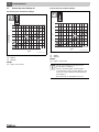
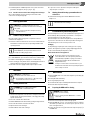
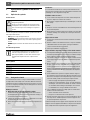
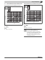
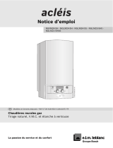
2.5 Pressure drop curve of heating coil
Pressure drop curve of bottom heat exchanger
Fig. 3 Pressure drop curve of bottom heat exchanger
[1] SM80/5
[2] SM100/5
Example:
[A] 8 gpm, 2.2feed of head
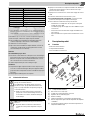
Pressure drop curve of top heat exchanger
Fig. 4 Pressure drop curve of top heat exchanger
[1] SM80/5
[2] SM100/5
Example:
[B] 8 gpm, 1.4 feed of head
20.00
feed of head
gpm
15.00
10.00
5.00
0.00
4.00 6.00 8.00 10.00 12.00 14.00 16.00
6 720 800 155-18.2T
1
2
A
18.00
20.00 22.00 24.00
26.00 28.00
feed of head
If the two heat exchangers are piped in series, the
pressure drops are cumulative.
If they are operated in parallel, a separate pump is
recommended for each heat exchanger. Otherwise, flow
setters are needed to regulate the flow through the two
heat exchangers.
Ensure that in any case the pumps meet the load.
6 720 800 155-19.2T
20.00
feed of head
gpm
15.00
10.00
5.00
0.00
4.00 6.00 8.00 10.00 12.00 14.00 16.00
1
2
B
18.00
20.00 22.00 24.00
26.00 28.00
feed of head

2
Product Information
SM80/5, SM100/5 – 6 720 800 156 (2017/07) 7
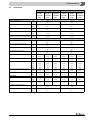
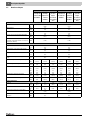
2.6 Technical Data
SM80/5 SM100/5
Lower heat
exchanger
connected to
boiler
Upper heat
exchanger
connected to
boiler
Both heat
exchangers in
series with the
boiler
Lower heat
exchanger
connected to
boiler
Upper heat
exchanger
connected to
boiler
Both heat
exchangers in
series with the
boiler
Tank capacity
Available capacity (total) gal
(l)
75.4
(285)
96.9
(366)
Maximum flow rate gpm
(l/min)
7.5
(28)
9.7
(37)
Maximum permissible DHW temperature °F
(°C)
203
(95)
203
(95)
Maximum permissible DHW operating pressure psi
(bar)
150
(10.3)
150
(10.3)
Stand-by heat loss (at 149 °F (65 °C) DHW
temperature, 68 °F (20 °C) room temperature)
°F/h
(K/h)
0.6
(0.34)
0.5
(0.28)
Storage tank performance
Cold water inlet temperature °F
(°C)
50
(10)
50
(10)
Domestic hot water outlet temperature °F
(°C)
140
(60)
140
(60)
DHW temperature rise °F
(°C)
90
(50)
90
(50)
Heat exchanger flow temperature °F
(°C)
176
(80)
176
(80)
Heat exchanger flow rate gpm
(l/h)
11.4
(2600)
11.4
(2600)
11.4
(2600)
14
(3180)
14
(3180)
14
(3180)
Heat exchanger pressure drop f o h
(mbar)
2.5
(74)
1.8
(53)
3.2
(95)
5.8
(175)
3.5
(106)
10.2
(305)
Continuous rating gph
(l/h)
gpm
(l/min)
185
(700)
3.1
(12)
135
(510)
2.2
(9)
298
(1128)
5.0
(19)
265
(1005)
4.4
(17)
153
(578)
2.5
(10)
376
(1422)
6.3
(24)
Amount that can be drawn off in the first hour gph
(l/h)
257
(973)
135
(510)
362
(1370)
356
(1348)
153
(578)
462
(1750)
Maximum heat input btu/hr
(kW)
112 398
(33)
78 187
(22.9)
178 797
(52.4)
169 083
(49.5)
87 856
(25.7)
235 434
(69)
Heat exchanger
Content gal
(liter)
2.3
(8.7)
1.6
(6.1)
3.8
(14.4)
3.1
(11.7)
1.9
(7.2)
4.9
(18.5)
Surface area ft
2
(m
2
)
13.99
(1.3)
9.69
(0.9)
23.68
(2.2)
19.38
(1.8)
10.76
(1)
30.14
(2.8)
Maximum heating water temperature °F
(°C)
230
(110)
230
(110)
Max. operating pressure, heat exchanger psi
(bar)
232
(16)
232
(16)
Table 5 Technical Data

2
Product Information
SM80/5, SM100/5 – 6 720 800 156 (2017/07)8
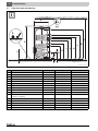
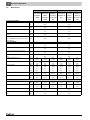
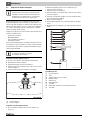
2.7 Physical and connection dimensions
Fig. 5 Physical and connection dimensions
SM80/5 SM100/5
A Diameter inch (mm) 26-3/8 (670) 26-3/8 (670)
B Minimum floor weight carrying capacity lb (kg) 899 (408) 1135 (515)
C Clearance off floor inch (mm) 3/8 - 3/4 (10 - 20) 3/8 - 3/4 (10 - 20)
D Overall height inch (mm) 58-7/8 (1495) 72-1/4 (1835)
E Height, cold water inlet inch (mm) 3-1/8 (80) 3-1/8 (80)
F Height, solar return inch (mm) 12-1/2 (318) 12-1/2 (318)
G Height, sensor well for temperature sensor (solar) inch (mm) 24-21/64 (618) 31-7/32 (793)
H Height, solar supply inch (mm) 28-1/2 (722) 35-3/8 (898)
i Height, tank return inch (mm) 32 (813) 40-5/8 (1033)
J Height, recirculation connection inch (mm) 35-1/2 (903) 45 (1143)
K Height, sensor well for temperature sensor
(heat source or aquastat)
inch (mm) 39-7/8 (1013) 50-5/16 (1278)
V Boiler flow connection height inch (mm) 44 (1118) 54-1/2 (1383)
M Height, hot water outlet inch (mm) 53-3/8 (1355) 66-3/4 (1695)
N Minimum room height for anode replacement inch (mm) 72-7/8 (1850) 82-3/4 (2100)
O Empty weight lb (kg) 260 (118) 298 (135)
P Total weight when filled lb (kg) 899 (408) 1135 (515)
Table 6
C
D
E
F
H
I
J
K
L
M
N
G
B
A
O
P
M1
M2
6 720 800 155-21.2ITL
B

3
Standards, regulations and directives
SM80/5, SM100/5 – 6 720 800 156 (2017/07) 9
3 Standards, regulations and directives
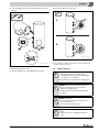
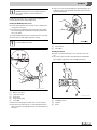
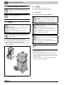
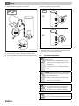
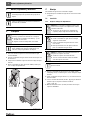
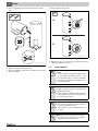
4 Moving the tank
▶ Position the dolly at the back of the packed DHW tank.
▶ Secure the DHW tank to the means of transportation with a strap.
▶ Transport the DHW tank to the installation location.
▶ Only remove the DHW tank from the packaging at the installation
location.
Fig. 6 Transporting with a dolly
5 Installation
The DHW tank is delivered fully assembled.
▶ Check DHW tank for completeness and damage.
5.1 Tank installation
5.1.1 Requirements for installation location
▶ Place the DHW tank on a plinth if there is a risk that water may collect
at the installation site.
▶ The installation site must be a dry and frost-free room.
▶ Observe minimum room height ( Tab. 6, page 8) and minimum
wall clearance in installation room ( Fig. 7, page 10).
▶ Maintain a distance of 2" (51 mm) from heated pipes and
combustible surfaces.
5.1.2 Wall clearances
Observe all local regulations and standards applicable to
installation and operation of the system in your country!
All electrical components must be approved for the USA
and Canada.
WARNING: Risk of injury from carrying heavy loads and
inadequately securing loads for transport.
▶ Use suitable means of transportation, e.g. a dolly
with strap.
▶ Secure the load against falling.
Where possible, do not remove the DHW tank from its
packaging until it has reached the installation location.
This ensures protection during handling.
6 720 647 567-02.1ITL
NOTICE: Risk of damage from inadequate load-bearing
capacity of the supporting substructure or unsuitable
floor surface!
▶ Ensure that the installation area is level and offers
sufficient load-bearing capacity.
NOTICE: Risk of damage from stress cracking and
corrosion!
▶ Position the DHW tank in a dry room free from the
risk of freezing.
▶ Install this DHW tank only in closed-loop, unvented
systems.
▶ Open expansion vessels can NOT be used for this
DHW tank.
NOTICE: If leaks can result in property damage or a drain
pan is required by law:
▶ Install an adequate drain pan.
▶ Follow the installation instructions of the drain pan
manufacturer.
Follow drain pan manufacturer's instructions.

5
Installation
SM80/5, SM100/5 – 6 720 800 156 (2017/07)10
Fig. 7 Recommended minimum wall clearances
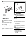
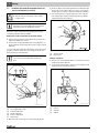
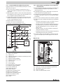
5.1.3 Positioning the tank
▶ Unpack the tank by removing the wrap, wooden boards and foam pad
on the top.
▶ Lay the foam pad on the floor to serve as a mat.
Fig. 8 Unpacking the DHW tank
▶ Carefully lay the tank on the foam pad [1].
▶ Cut out the protections in the foam bottom [2].
▶ Unscrewing the adjustable foot[3].
Fig. 9 Lay the DHW cylinder on its side and expose the adjustable foot
6 720 800 155-10.1ITL
15-¾ inch
4 inch
(102 mm)
(400 mm)
(500 mm)
19-¾ inch
6 720 647 567-05.1ITL
6 720 647 567-35.1ITL
1.
2.
3.

5
Installation
SM80/5, SM100/5 – 6 720 800 156 (2017/07) 11
▶ Position the DHW tank on a level floor with adequate load-bearing
capacity.
Fig. 10 Positioning the tank
▶ Maintain minimum wall clearances.
▶ Using the adjustable foot, align the DHW cylinder vertically.
▶ Remove the caps from the connections.
Fig. 11 Remove caps
▶ Use Teflon tape or Teflon cord to seal the connections. Do not use
hemp to seal the connections.
5.2 Water connections
6 720 647 567-07.1ITL
WARNING: Risk of fire from soldering and brazing!
▶ Take appropriate protective measures when
soldering and welding as the insulation is flammable,
for example, cover the insulation.
▶ Check tank jacket for damage after completing work.
DANGER: Risk of injury from contaminated water!
Work carried out without due care for cleanliness
contaminates the drinking water.
▶ Install in accordance with national standards and
guidelines.
NOTICE: Water damage
▶ Connect the drain to the bottom tank connection
prior to filling the tank.
▶ Seal off all unused tank connections.
NOTICE: Risk of corrosion from damage to the enamel
coating!
▶ Attach connections to the DHW tank only "hand-
tight".
6 720 800 155-22.1ITL
A
B

5
Installation
SM80/5, SM100/5 – 6 720 800 156 (2017/07)12
5.2.1 Connecting the tank on the water side
Example of system with all recommended valves ( Fig. 12, page 12).
▶ When selecting the expansion vessel for the hot water side, take the
content of the heat exchanger and DHW tank into consideration.
▶ Route the connection cables for the tank temperature sensors at the
back of the tank through the insulation to the heating appliance or
controller.
▶ Install piping runs so that natural circulation is prevented. If
necessary, install check valves.
▶ Install connection cables free of stress.
▶ Attach piping to the tank connections on-site.
▶ Check all connections for leaks.
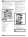
Fig. 12 Installation (illustrative)
[1] Storage tank
[2] Shutoff valve
[3] P&T safety valve (combined with hot water outlet)
[4] Check valve
[5] Tank primary pump
[6] Recirculation pump (optional)
[7] Air eliminator (in main supply)
[8] Drain valve
[9] Expansion vessel
[10] Thermostatic DHW mixing valve
[11] Tank primary pump
[12] Solar pump station
[AW] DHW outlet
[EZ] Recirculation inlet
[VS1] Tank supply (solar)
[RS1] Tank return (solar)
[VS2] Tank supply (boiler)
[RS2] Tank return (boiler)
[EK] Cold water inlet
[EL] Tank drain
5.2.2 Installing a T&P safety valve (on-site)
▶ Install a listed T&P safety valve that is approved for drinking water
( ¾ ")in the DHW outlet.
▶ This DHW tank must be installed with a new T&P safety valve.
▶ The T&P valve must be sized no smaller than the rated tank capacity.
▶ Observe the safety valve installation instructions.
▶ T&P discharge pipe:
– The blow-off line must be at least equal to the outlet cross-section
of the safety valve.
– Route the blow-off line from the T&P valve directly to an adequate
drain (maximum length 6 ft (2 m) with no more than two 90°-
elbows).
– The discharge line must terminate at an adequate drain in order to
prevent property damage from spillage.
– Check that the T&P safety valve operates properly at least once
annually.
▶ Never plug the blow-off line. During heating, water may be
discharged for operational reasons at any time.
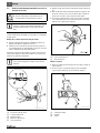
Fitting the B-kit
Fig. 13 Connecting the DHW tank components
[1] Tee 1" x 1" x 3/4" (2x) with T&P safety valve
[2] 3/4" cap for recirculation connection
[3] Bracket with Aquastat
[4] Tee with fill and drain valve
5.3 Installing the DHW water temperature sensor
(accessory) or Aquastat (accessory)
6 720 800 155-11.1ITL
1
1
DANGER: Risk of fatal injury from electric shock.
▶ Isolate the system electrically prior to commencing
work on the system.
6 720 800 155-05.1ITL

5
Installation
SM80/5, SM100/5 – 6 720 800 156 (2017/07) 13
Install a tank temperature sensor or an aquastat on the DHW tank to
measure and monitor the hot water temperature.
Installing the DHW temperature sensor
▶ Take the tank temperature sensor from the scope of delivery of the
control panel (accessories).
▶ Insert the sensor set until it bottoms out inside the sensor well [5].
This automatically pushes back the plastic spiral [3] that holds the
sensor set together.
The compensating spring [4] ensures contact between the sensor well
and sensor surfaces, and a reliable temperature reading.
Fig. 14 Installing the DHW temperature sensor
[1] Quarter-circle spacer
[2] Temperature sensor
[3] Plastic spiral
[4] Compensating spring
[5] Sensor Well
▶ Push sensor retaining clip [1] from the side onto sensor well [2].
▶ Route the sensor lead to the boiler or control panel and ensure the
cable is not strained. This piping must not be in contact with any hot
boiler parts.
▶ In the case a sensor is being used without a compensating spring, the
empty space in the sensor well must be filled with a sufficient amount
of heat-conducting paste.
Fig. 15 Installing the sensor retainer
[1] Sensor retainer
[2] Sensor Well
Installing the aquastat
▶ Remove cover from the aquastat. To do so, undo the screw on the
top.
▶ If necessary, remove any unnecessary attachments. Attach bracket
[3] to aquastat [2] by means of two self-tapping screws [1].
Fig. 16 Screw the bracket onto the aquastat
[1] Self-tapping screws
[2] Aquastat
[3] Holder
Connect the electrical power and set the temperature on
the DHW temperature sensor or the aquastat as shown in
the respective aquastat or control manufacturer's
instructions.
Always ensure that the full length of the sensor surface is
in contact with the sensor well.
6 720 800 155-17.1ITL
5
4
123
6 720 800 155-03.1ITL

5
Installation
SM80/5, SM100/5 – 6 720 800 156 (2017/07)14
▶ Feed the temperature sensor [4] with the compensating spring [3]
into the sensor well [5].
▶ Attach bracket [6] to DHW cylinder by means of 4 self-tapping sheet
metal screws [1].
▶ Replace the cover of the aquastat [2].
Fig. 17 Installing the aquastat
[1] Self-tapping screws
[2] Aquastat
[3] Compensating spring
[4] Temperature sensor
[5] Sensor Well
[6] Holder
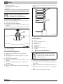
5.4 Connecting the KS solar pump station
▶ Attach the KS solar pump station [4] to the lower heat exchanger in
the DHW tank at the VS
1
(solar supply) and RS
1
(solar return)
connections.
▶ Attach the reheating device to the upper heat exchanger in the DHW
tank at the VS2 (storage tank supply) and RS2 (storage tank return)
connections.
▶ Use piping and pipe connections made of copper, brass and non-
galvanized steel for the connection between the KS solar pump
station [4] and DHW tank [5].
Fig. 18 Connecting the KS solar pump station (schematic illustration)
[1] Collector supply connection
[2] Collector return connection
[3] Oil-/gas-fired boiler
[4] Solar pump station
[5] DHW tanks
Grounding the piping
▶ Attach one grounding clamp each to the supply and return pipes (at
any position).
▶ Connect the grounding clamps to the building's grounding rod by
means of standard bonding cables AWG9.
Laying pipes with an automatic air vent valve on the roof (available
as accessory)
▶ Pipes to the air vent valve should follow a rising gradient. For every
downwards change of direction, an additional air separator with air
vent valve is required (heat-resistant to 302 °F (150 °C)).
5.5 Connection as high-performance DHW tank
The DHW tank can also be used as a high-performance DHW tank.
In this case, 2 connection configurations are possible.
5.5.1 Series connection of the lower and upper heat exchanger
▶ Attach the upper connection on the lower heat exchanger to the
lower connection on the upper heat exchanger in the DHW tank.
▶ Attach the tank charging pump to the upper connection on the upper
heat exchanger.
▶ Attach the lower connection on the lower heat exchanger to the
return piping on the boiler.
WARNING: Risk of equipment damage from very high
operating temperatures and pressures!
▶ Use pressure- and temperature-resistant piping
materials.
▶ Do not use any galvanized piping, pipe connections
or graphite seals.
▶ Do not use any plastic piping or connections of any
kind.
▶ When using soldered connections in the entire solar
circuit, use high-temperature solder (melting point
455 °F (235 °C)).
To ensure proper operation of the solar thermal system,
air must be bled adequately from the entire system.
For information on bleeding the solar thermal system,
refer to the installation instructions for the KS solar
pump station.
6 720 800 155-04.1ITL
5
4
3
2 1
6
Allow only an authorized contractor to make all the
piping connections.
When the heat exchangers are connected in series, the
pressure loss across the two coils is cumulative.
Pressure drop of connecting pipe must be added. Ensure
that the pump used can handle the resulting pressure
drop.

6
Start-up procedure
SM80/5, SM100/5 – 6 720 800 156 (2017/07) 15
▶ Install the Aquastat or DHW temperature sensor in the sensor well
provided for this purpose ( Fig. 2, page 5, [3]).
5.5.2 Parallel connection of the lower and upper heat exchanger
We recommend that the two heat exchangers in the tank each be
connected to its own primary pump.
6 Start-up procedure
6.1 Commissioning the DHW tank
Have the installer of the heating system or a qualified contractor
commission the equipment.
▶ Commission the boiler and other accessories in accordance with the
manufacturer's instructions in the corresponding installation and
operating manuals.
▶ To bleed air from the DHW tank, open the highest tap/valve.
▶ To fill the DHW tank, open the shut-off valve for the cold water inlet.
▶ Flush the tank and piping thoroughly prior to commissioning.
▶ Before heating up, verify that the boiler, tank and pipework are filled
with water. Open the air bleeder valve for this purpose.
▶ Check all connections, piping and the inspection port for leaks.
7 Shutdown
7.1 Shutting down the tank
▶ Switch off the temperature controller at the control panel, shut of the
heating system emergency shutoff switch, or disengage the heating
system circuit breaker.
▶ Close the cold water inlet shutoff valve.
▶ Drain the DHW tank via the drain valve by opening the highest faucet.
▶ Close the shut-off valves to and from the boiler.
▶ Depressurize the heat exchanger.
▶ Drain and blow out the heat exchanger.
▶ To prevent corrosion, dry out the inner space and keep the
inspection port covers open.
7.2 Shutting down the heating system when there is a
risk of frost
▶ Shut down the heating system and the DHW tank as shown in
Chapter 7.1.
8 Environmental protection/disposal
Environmental protection is one of the fundamental company policies of
the Bosch Group. We regard quality of performance, economy and
environmental protection as equal objectives.
Environmental protection laws and regulations are strictly adhered to.
To protect the environment, we use the best possible technology and
materials taking into account economic points of view.
Packaging
For the packaging, we participate in the country-specific recycling
systems, which guarantee optimal recycling. All packaging materials
used are environmentally-friendly and recyclable.
Old electrical and electronic appliances
Electrical or electronic devices that are no longer
serviceable must be collected separately and sent for
environmentally compatible recycling (in accordance
with the European Waste Electrical and Electronic
Equipment Directive).
To dispose of old electrical or electronic devices, you
should use the return and collection systems put in place
in the country concerned.
9 Maintenance
▶ Allow the DHW tank to cool down sufficiently before performing any
maintenance.
▶ Remedy all faults immediately.
▶ Use original spare parts only!
▶ The tank must be inspected annually and maintained as required.
▶ Check the T&P safety valve annually.
9.1 Preparing the DHW tank for cleaning
▶ Disconnect electrical power from the heating system.
▶ Drain the DHW tank. To do so, close the shut-off valve for cold water
inlet and the open drain valve. To vent the system, open the air vent
valve or the highest faucet.
▶ Remove the cleanout cover [6] shroud over the inspection port [1] in
the DHW tank.
NOTICE: Risk of equipment damage from excess
pressure! Excess pressure can cause stress cracking in
the enamel.
▶ Never close the temperature and pressure safety
valve blow-off line.
Use only drinking water to check the DHW tank for leaks.
On the DHW side, the test pressure must not exceed
150 psi (10.3 bar) gauge pressure.
NOTICE: Risk of tank damage!
Residual moisture can result in corrosion.
▶ Thoroughly dry out the inside (e. g. by means of hot
air) and leave the cleanout cover open.
WARNING: Risk of scalding from hot water!
▶ Let the tank cool down sufficiently.
Drain the DHW tank completely, even the lower chamber
of the tank and the heat exchanger.
WARNING: Risk of scalding!
Hot water can cause scalding.
▶ Prior to cleaning, allow the DHW tank to cool down
sufficiently.

9
Maintenance
SM80/5, SM100/5 – 6 720 800 156 (2017/07)16
▶ Loosen the hex bolts [5] in the cleanout cover [4].
▶ Remove the cleanout cover [4], magnesium anode [3] and cleanout
cover gasket [2].
Fig. 19 Removing the cleanout cover
[1] Inspection port
[2] Handhole cover gasket
[3] Magnesium anode
[4] Handhole cover
[5] Hex bolts
[6] Cleanout cover shroud
9.2 Descaling/cleaning the tank
▶ Check the DHW tank interior for scale deposits (calcium).
Should limescale be discovered inside the DHW tank, proceed as
follows:
▶ Hose down the inside of the DHW tank with a "high pressure"
(approx. 58 – 72.5 psi (4 – 5 bar) gauge pressure) stream of cold
water ( Fig. 20, page 16).
You can increase the cleaning effect by heating up the heat exchangers
in the drained DHW tank before cleaning. The thermal shock effect
releases scale deposits more easily from the coil-type heat exchanger.
▶ Use a wet & dry vacuum cleaner with plastic suction hose to remove
the residues.
Extremely tough limescale inside the DHW tank can be removed by
chemical means. We recommend that you have a qualified contractor
carry out the chemical cleaning operation.
Fig. 20 Hosing down the interior of the DHW tank
9.3 Check the magnesium anodes
The purpose of the magnesium anode is to protect the storage tank
against corrosion.
Every year, check whether the magnesium anode must be replaced. The
surface of the magnesium anode must be free of deposits.
If the rod surface appears pitted, bumpy, rusty, deposits have built up on
the surface, or if the rod is less than 5/8" (15 mm) in diameter, then it
must be replaced.
Certain installations may require more frequent replacement of the
magnesium anode rod:
• Recirculation connection
• Poor water quality
• Galvanic/electrolytic corrosion
• High flow rate
In the event of poor water quality it is recommended that a water
treatment professional be consulted for water treatment options. The
DHW cylinder warranty is void if the magnesium anode is not correctly
maintained.
Checking the top magnesium anode
▶ Remove PS top cover if not already removed.
▶ Unscrew the magnesium anodes.
▶ Check the magnesium anodes for degradation.
▶ Replace the magnesium anode if the diameter has decreased to
approx. 5/8" (15 mm).
NOTICE: Risk of tank damage due to damaged enamel.
▶ Never use hard objects or tools with sharp edges to
clean the interior of the tank.
6720 800 155-02.1ITL
The warranty is void if the magnesium anode is not
correctly maintained. Annual service records must be
kept in a safe location and submitted together with the
original purchase receipt in the event of a warranty
claim.
Never bring the magnesium anode surface into contact
with oil or grease.
▶ Keep everything clean.

9
Maintenance
SM80/5, SM100/5 – 6 720 800 156 (2017/07) 17
▶ Insert the magnesium anodes into the sleeve again.
Fig. 21 Checking the top magnesium anode
[1] Hex bolt
[2] Magnesium anode
Checking the side magnesium anode
▶ Empty the DHW cylinder as described in Chapter 9.1.
▶ Remove cleanout cover ( Fig. 19, page 16), if it is not already
removed.
▶ Check the magnesium anodes.
▶ Replace the magnesium anode if the diameter has decreased to
approx. 5/8" (15 mm).
▶ Unscrew the nut M8 [9] to release the eyelet of the grounding cable
connecting lead[8].
▶ Unscrew the M8 nut [7].
▶ Remove the handhole cover [1] from the magnesium anode [3].
▶ Fit the new magnesium anode together with all small parts supplied
with it.
Fig. 22 Replacing the magnesium anode
Key to Fig. 22:
[1] Magnesium anode
[2] Gasket
[3] Handhole cover
[4] Insulating sleeve
[5] Dished washer
[6] Serrated washer
[7] M8 Nut
[8] Eyelet of the grounding cable connecting lead
[9] M8 Nut
9.4 Startup after maintenance
▶ Put the cleanout cover [4] back in place together with the new gasket
[2].
▶ Thread hex bolts [5] into cleanout cover [4] "hand-tight".
▶ Then use a torque wrench to tighten the hex bolts to 18-22 lbf-ft
(25 – 30 Nm).
▶ Fill the DHW tank and restart the heating system.
▶ Check all connections and the inspection port for leaks.
▶ Replace the cleanout cover shroud.
▶ Reinstall the PS jacket cover ( Fig. 2, page 5) on the DHW tank.
Fig. 23 Reinstall handhole cover
[1] Inspection port
[2] Handhole cover gasket
[3] Magnesium anode
[4] Handhole cover
[5] Hex bolts
[6] Cleanout cover shroud
6 720 800 155-23.1ITL
NOTICE: Risk of tank damage from a faulty gasket!
▶ To prevent the DHW tank from leaking, install a new
cleanout cover gasket upon completion of cleaning
and maintenance.
6720 800 155-02.1ITL

10
Spare Parts
SM80/5, SM100/5 – 6 720 800 156 (2017/07)18
10 Spare Parts
10.1 Spare parts for SM80/5, SM100/5
Fig. 24 DHW tank SM80/5, SM100/5
6 720 800 155-20.1ITL
1
2
10
5
5
5
14
13
6
3
9
8
5
9
11
7
9
Item Description Part number
1 Cover D670 lid, black 8 718 541 369 0
2 Plug, EPS upper part D672.5 8 718 541 767 0
3 Cleanout gasket D670, black 8 718 542 063 0
5 Self-tapping hex screw M10x25 (8x) 7 747 005 744
6 Cleanout cover DN120 for anode 7 747 004 739
7 O-ring 120.02x6.99-N 8 718 572 538 0
8 Anode D33x400 mm 8 718 571 568 0
9 Anode mounting kit (10x) screw-in 5264278
Table 7 Spare parts for SM80/5, SM100/5
10 Anode G1 1/2 x 750,
without electrical insulation D=33
8 718 542 778 0
10 Anode G1 1/2 x 600,
without electrical insulation D=40
8 718 542 704 0
11 Anode grounding cable (insulated) 63037168
13 Self-tapping screw St 4.2x13 (10x) 7 747 027 696
14 Retaining plate for the aquastat 7 747 028 761 0
Logo Buderus 8 718 541 573
Item Description Part number
Table 7 Spare parts for SM80/5, SM100/5

Table des matières
SM80/5, SM100/5 – 6 720 800 156 (2017/07) 19
Table des matières
1 Explication des symboles et mesures de sécurité . . . . . . . . . 20
1.1 Explication des symboles . . . . . . . . . . . . . . . . . . . . . . . 20
1.2 Consignes de sécurité . . . . . . . . . . . . . . . . . . . . . . . . . . 20
1.3 Initiation de l’utilisateur . . . . . . . . . . . . . . . . . . . . . . . . . 21
2 Description du produit . . . . . . . . . . . . . . . . . . . . . . . . . . . . . . . 21
2.1 Fourniture . . . . . . . . . . . . . . . . . . . . . . . . . . . . . . . . . . . . 21
2.2 Utilisation conforme à l’usage prévu . . . . . . . . . . . . . . . 22
2.3 Description du produit . . . . . . . . . . . . . . . . . . . . . . . . . . 22
2.4 Plaque signalétique . . . . . . . . . . . . . . . . . . . . . . . . . . . . 22
2.5 Courbe des pertes de pression échangeur thermique . 23
2.6 Données techniques . . . . . . . . . . . . . . . . . . . . . . . . . . . 24
2.7 Cotes de construction et de raccordement . . . . . . . . . 25
3 Normes, prescriptions et directives . . . . . . . . . . . . . . . . . . . . 26
4 Transport . . . . . . . . . . . . . . . . . . . . . . . . . . . . . . . . . . . . . . . . . . . 26
5 Montage . . . . . . . . . . . . . . . . . . . . . . . . . . . . . . . . . . . . . . . . . . . . 26
5.1 Mise en place . . . . . . . . . . . . . . . . . . . . . . . . . . . . . . . . . 26
5.1.1 Exigences requises pour le lieu d’installation . . . . . . . . 26
5.1.2 Distances par rapport aux murs . . . . . . . . . . . . . . . . . . 27
5.1.3 Mise en place du ballon d’eau chaude sanitaire . . . . . . 27
5.2 Raccordements hydrauliques . . . . . . . . . . . . . . . . . . . . 28
5.2.1 Effectuer le raccordement hydraulique du ballon d’eau
chaude sanitaire . . . . . . . . . . . . . . . . . . . . . . . . . . . . . . 29
5.2.2 Installer la soupape de sécurité pour la température
et la pression (sur site) . . . . . . . . . . . . . . . . . . . . . . . . . 29
5.3 Installation de la sonde de température ECS
(accessoire) ou de l’Aquastat (accessoire) . . . . . . . . . 30
5.4 Raccordement de la station de pompe solaire KS . . . . 31
5.5 Raccordement en tant que ballon ECS grande
puissance . . . . . . . . . . . . . . . . . . . . . . . . . . . . . . . . . . . . 31
5.5.1 Raccordement en série des échangeurs thermiques
inférieur et supérieur . . . . . . . . . . . . . . . . . . . . . . . . . . 31
5.5.2 Raccordement en parallèle des échangeurs thermiques
inférieur et supérieur . . . . . . . . . . . . . . . . . . . . . . . . . . 32
6 Mise en service . . . . . . . . . . . . . . . . . . . . . . . . . . . . . . . . . . . . . . 32
6.1 Mise en service du ballon d’eau chaude sanitaire . . . . 32
7 Mise hors service . . . . . . . . . . . . . . . . . . . . . . . . . . . . . . . . . . . . 32
7.1 Mise hors service du ballon d’eau chaude sanitaire . . . 32
7.2 Mise hors service de l’installation de chauffage
en cas de risques de gel . . . . . . . . . . . . . . . . . . . . . . . . 32
8 Protection de l’environnement/
Recyclage . . . . . . . . . . . . . . . . . . . . . . . . . . . . . . . . . . . . . . . . . . 32
9 Entretien . . . . . . . . . . . . . . . . . . . . . . . . . . . . . . . . . . . . . . . . . . 33
9.1 Préparer le ballon d’eau chaude sanitaire pour le
nettoyage . . . . . . . . . . . . . . . . . . . . . . . . . . . . . . . . . . . . .33
9.2 Détartrer/nettoyer le ballon d'eau chaude sanitaire . . 33
9.3 Vérifier les anodes en magnésium . . . . . . . . . . . . . . . . 33
9.4 Mise en service après maintenance . . . . . . . . . . . . . . . 34
10 Pièces de rechange . . . . . . . . . . . . . . . . . . . . . . . . . . . . . . . . . . 36
10.1 Pièces de rechange pour SM80/5, SM100/5 . . . . . . . 36

1
Explication des symboles et mesures de sécurité
SM80/5, SM100/5 – 6 720 800 156 (2017/07)20
1 Explication des symboles et mesures de
sécurité
1.1 Explication des symboles
Avertissements
Les mots de signalement suivants sont définis et peuvent être utilisés
dans le présent document :
• AVIS signale le risque de dégâts matériels.
• PRUDENCE signale le risque d’accidents corporels légers à moyens.
• AVERTISSEMENT signale le risque d’accidents corporels graves à
mortels.
• DANGER signale la survenue d’accidents mortels en cas de non res-
pect.
Informations importantes
Autres symboles
1.2 Consignes de sécurité
Lisez attentivement toutes les consignes avant l’installation. Exécuter
les étapes dans l’ordre indiqué. Faire contrôler le ballon d’eau chaude
sanitaire par un technicien qualifié au moins une fois par an. Le non-res-
pect de ces consignes peut entraîner des accidents graves voire mortels
et/ou des dégâts matériels.
Montage et entretien
▶ Risque d’incendie en raison des travaux de soudure !
L’isolation thermique étant inflammable, prendre des mesures de
sécurité appropriées pour effectuer tous les travaux de soudage, en
recouvrant l’isolation thermique par ex.
▶ S’assurer que les travaux d’installation et de maintenance sont exclu-
sivement réalisés par un professionnel agréé.
▶ Utiliser des matériaux suffisamment résistants aux températures éle-
vées.
Interdiction :
Il est formellement interdit de raccorder le potentiostat d'une anode
externe à l'anode au magnésium montée dans un ballon ! Le ballon serait
endommagé ! Le droit de garantie serait perdu.
Installation et mise en service
▶ Le raccordement électrique doit être réalisé exclusivement par un
électricien. Respecter le schéma de connexion !
▶ Ne pas monter cet appareil dans des pièces humides (par ex. salle de
bain, sauna).
Fonction
▶ Respecter cette notice d’installation et d’entretien afin de garantir un
fonctionnement parfait.
▶ Ne pas obturer la conduite de purge de la soupape de sécurité T&D.
Pendant le chauffage, de l’eau risque de s’écouler pour des raisons
de sécurité.
Risques d’électrocution
▶ S’assurer que seuls des électriciens autorisés réalisent ces travaux
électriques.
▶ Avant de commencer les travaux d’électricité, couper le courant du
câble d’alimentation sur tous les pôles et protéger l’installation
contre tout réenclenchement involontaire.
▶ Vérifier que l’installation est hors tension.
Risques de brûlure aux points de puisage de l’eau chaude sanitaire
▶ Les températures du ballon d’eau chaude sanitaire pendant son fonc-
tionnement peuvent dépasser 122 °F (50 °C). Pour limiter la tempé-
rature de puisage, installer un mélangeur thermostatique.
▶ L’eau chauffée utilisée pour la lessive, la vaisselle et d’autres tâches
de nettoyage peut provoquer des brûlures et des blessures perma-
nentes.
▶ Chez les enfants, les personnes âgées et sénile ou mentalement han-
dicapée, il existe un risque accru de blessure permanente à l’eau
chaude. Ne jamais laisser ces personnes sans surveillance dans la
baignoire ou sous la douche. Ne pas autoriser les jeunes enfants à
actionner eux-mêmes les robinets d’eau chaude ou de remplir une
baignoire.
▶ Si dans un bâtiment les personnes comprises dans les catégories
précédemment citées actionnent des robinets d’eau chaude ou si les
directives locales imposent des températures précises pour les robi-
nets d’eau chaude, prendre les mesures spécifiques suivantes :
– Utiliser le réglage de température le plus bas possible.
– Installer une sécurité anti-brûlure, par ex. une vanne mélangeur
automatique, sur le robinet d’eau chaude ou le chauffe-eau. Choi-
sir et installer la vanne mélangeur automatique en fonction des
recommandations et consignes du fabricant de la vanne.
▶ L’eau s’échappant des vannes de vidange peut être extrêmement
chaude. Pour éviter les blessures :
– Assurer l’étanchéité des raccordements.
– Eloigner les écoulements d’eau de toute personne.
▶ Prendre des mesures de protection contre les températures et pres-
sions trop élevées ! Installer impérativement une soupape de sécu-
rité pour la température et la pression.
Le tableau suivant présente le rapport entre la température de l’eau et le
temps nécessaire à l’apparition de brûlures. Vous pouvez ainsi détermi-
ner les températures d’eau les plus sûres pour votre application.
Les avertissements sont indiqués dans le texte par un
triangle de signalisation.
En outre, les mots de signalement caractérisent le type
et l’importance des conséquences éventuelles si les me-
sures nécessaires pour éviter le danger ne sont pas res-
pectées.
Les informations importantes ne concernant pas de si-
tuations à risques pour l'homme ou le matériel sont si-
gnalées par le symbole ci-contre. Elles sont limitées par
des lignes dans la partie inférieure et supérieure du
texte.
Symbole Fonction
▶Etape à suivre
Renvois à un autre passage dans le document
• Enumération/Enregistrement dans la liste
– Enumération / Entrée de la liste (2e niveau)
Tab. 1
La page charge ...
La page charge ...
La page charge ...
La page charge ...
La page charge ...
La page charge ...
La page charge ...
La page charge ...
La page charge ...
La page charge ...
La page charge ...
La page charge ...
La page charge ...
La page charge ...
La page charge ...
La page charge ...
La page charge ...
La page charge ...
La page charge ...
La page charge ...
La page charge ...
La page charge ...
La page charge ...
La page charge ...
La page charge ...
La page charge ...
La page charge ...
La page charge ...
La page charge ...
La page charge ...
La page charge ...
La page charge ...
La page charge ...
La page charge ...
La page charge ...
La page charge ...
-
 1
1
-
 2
2
-
 3
3
-
 4
4
-
 5
5
-
 6
6
-
 7
7
-
 8
8
-
 9
9
-
 10
10
-
 11
11
-
 12
12
-
 13
13
-
 14
14
-
 15
15
-
 16
16
-
 17
17
-
 18
18
-
 19
19
-
 20
20
-
 21
21
-
 22
22
-
 23
23
-
 24
24
-
 25
25
-
 26
26
-
 27
27
-
 28
28
-
 29
29
-
 30
30
-
 31
31
-
 32
32
-
 33
33
-
 34
34
-
 35
35
-
 36
36
-
 37
37
-
 38
38
-
 39
39
-
 40
40
-
 41
41
-
 42
42
-
 43
43
-
 44
44
-
 45
45
-
 46
46
-
 47
47
-
 48
48
-
 49
49
-
 50
50
-
 51
51
-
 52
52
-
 53
53
-
 54
54
-
 55
55
-
 56
56


Buderus SM80/5 Installation And Service Instructions Manual
- Taper
- Installation And Service Instructions Manual
- Ce manuel convient également à
dans d''autres langues
- English: Buderus SM80/5
- español: Buderus SM80/5
Documents connexes
Autres documents
-
 Honeywell Home MX129LF Guide d'installation
-
Bradford White BMT2V0200NACK5XC Manuel utilisateur
-
Laars MT2H0300NACK2BXN Guide d'installation
-
Chaffoteaux & Maury BK1S 850 Le manuel du propriétaire
-
 ELM LEBLANC MEGALIS NGVA 24-5H V 24 KW Le manuel du propriétaire
-
Atlantic BALLON ANNULAIRE DUOTHERM 200L Le manuel du propriétaire
-
Hunter 43658 Manuel utilisateur
-
 ELM LEBLANC ACLEIS NGVM V Le manuel du propriétaire
-
Watts CO-190-PR, CO-190-PR-60, CO-1190-PR, CO-1190-PR-60 Guide d'installation
-
Drive AquaSense 3-in-1 Contoured Raised Toilet Seat Le manuel du propriétaire


