3M DBI-SALA® Roof Top Anchor 2100138, 1 EA Mode d'emploi
- Taper
- Mode d'emploi

© Copyright 2013, Capital Safety
ANSI Z359.1 OSHA
This manual is intended to meet the Manufacturer’s
Instructions as required by ANSI Z359.1 and should
be used as part of an employee training program as
required by OSHA.
INSTRUCTION MANUAL
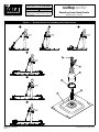
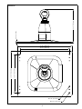
Figure 1 – Rooftop Anchor for Standing Seam Metal Roofs
1 2 3
4
A
B
F
E
C
D
5
6
FORM NO: 5903505
REV: A
rooftop anchor
Standing Seam Metal Roofs
Model Number: 2100138
The Ultimate in Fall Protection

2
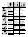
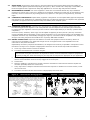
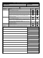
Table 1 – 2100138 Rooftop Anchor Applications and Required Seam Clamps
Required Clamps
S
S
Bulb Type Standing Seam
1
Vertical Folded Standing Seams
1
Horizontal Folded Standing Seams
1
EZ-Stop™ and Force2™
Energy Absorbing Lanyard
7241204 “Z” Clamp Kit:
• 4 Clamps - One clamp in each corner
of Baseplate
• Mounting Bolt - Torque to:
22 ft-lbs (30 Nm)
• Setscrews - Torque to:
22 ga Steel 160-180 in-lbs (18-20 Nm)
24 ga Steel 130-150 in-lbs (14-17 Nm)
Other Metals
(22-24 ga)
130-150 in-lbs (14-17 Nm)
7241206 “E” Clamp Kit or
7241208 “U” Clamp Kit:
• 4 Clamps - One clamp in each corner
of Baseplate
• Mounting Bolt - Torque to:
22 ft-lbs (30 Nm)
• Setscrews - Torque to:
22 ga Steel 160-180 in-lbs (18-20 Nm)
24 ga Steel 130-150 in-lbs (14-17 Nm)
Other Metals
(22-24 ga)
130-150 in-lbs (14-17 Nm)
7241208 “U” Clamp Kit if S>0.5” or
7241206 “E” Clamp if S≤0.5”:
• 4 Clamps - One clamp in each corner
of Baseplate
• Mounting Bolt - Torque to:
22 ft-lbs (30 Nm)
• Setscrews - Torque to:
22 ga Steel 160-180 in-lbs (18-20 Nm)
24 ga Steel 130-150 in-lbs (14-17 Nm)
Other Metals
(22-24 ga)
130-150 in-lbs (14-17 Nm)
DBI-SALA
®
or Protecta
®
Leading Edge Rated
Self-Retracting Lifeline
7241204 “Z” Clamp Kit:
• 4 Clamps - One clamp in each corner
of Baseplate
• Mounting Bolt - Torque to:
22 ft-lbs (30 Nm)
• Setscrews - Torque to:
22 ga Steel 160-180 in-lbs (18-20 Nm)
24 ga Steel 130-150 in-lbs (14-17 Nm)
Other Metals
(22-24 ga)
130-150 in-lbs (14-17 Nm)
7241206 “E” Clamp Kit or
7241208 “U” Clamp Kit:
• 4 Clamps - One clamp in each corner
of Baseplate
• Mounting Bolt - Torque to:
22 ft-lbs (30 Nm)
• Setscrews - Torque to:
22 ga Steel 160-180 in-lbs (18-20 Nm)
24 ga Steel 130-150 in-lbs (14-17 Nm)
Other Metals
(22-24 ga)
130-150 in-lbs (14-17 Nm)
7241208 “U” Clamp Kit if S>0.5” or
7241206 “E” Clamp if S≤0.5”:
• 4 Clamps - One clamp in each corner
of Baseplate
• Mounting Bolt - Torque to:
22 ft-lbs (30 Nm)
• Setscrews - Torque to:
22 ga Steel 160-180 in-lbs (18-20 Nm)
24 ga Steel 130-150 in-lbs (14-17 Nm)
Other Metals
(22-24 ga)
130-150 in-lbs (14-17 Nm)
DBI-SALA
®
or Protecta
®
Rope
Grabs or Rope Adjusters and
Vertical Lifelines
7241204 “Z” Clamp Kit:
• 4 Clamps - One clamp in each corner
of Baseplate
• Mounting Bolt - Torque to:
22 ft-lbs (30 Nm)
• Setscrews - Torque to:
22 ga Steel 160-180 in-lbs (18-20 Nm)
24 ga Steel 130-150 in-lbs (14-17 Nm)
Other Metals
(22-24 ga)
130-150 in-lbs (14-17 Nm)
7241206 “E” Clamp Kit or
7241208 “U” Clamp Kit:
• 4 Clamps - One clamp in each corner
of Baseplate
• Mounting Bolt - Torque to:
22 ft-lbs (30 Nm)
• Setscrews - Torque to:
22 ga Steel 160-180 in-lbs (18-20 Nm)
24 ga Steel 130-150 in-lbs (14-17 Nm)
Other Metals
(22-24 ga)
130-150 in-lbs (14-17 Nm)
7241208 “U” Clamp Kit if S>0.5” or
7241206 “E” Clamp if S≤0.5”:
• 4 Clamps - One clamp in each corner
of Baseplate
• Mounting Bolt - Torque to:
22 ft-lbs (30 Nm)
• Setscrews - Torque to:
22 ga Steel 160-180 in-lbs (18-20 Nm)
24 ga Steel 130-150 in-lbs (14-17 Nm)
Other Metals
(22-24 ga)
130-150 in-lbs (14-17 Nm)
Sayfl ine™ Synthetic Rope
Horizontal Lifeline
7241204 “Z” Clamp Kit:
• 2 Kits: 4 Clamps per Anchor - One
clamp in each corner of Baseplate
• Mounting Bolt - Torque to:
22 ft-lbs (30 Nm)
• Setscrews - Torque to:
22 ga Steel 160-180 in-lbs (18-20 Nm)
24 ga Steel 130-150 in-lbs (14-17 Nm)
Other Metals
(22-24 ga)
130-150 in-lbs (14-17 Nm)
7241206 “E” Clamp Kit or
7241208 “U” Clamp Kit:
• 2 Kits: 4 Clamps per Anchor - One
clamp in each corner of Baseplate
• Mounting Bolt - Torque to:
22 ft-lbs (30 Nm)
• Setscrews - Torque to:
22 ga Steel 160-180 in-lbs (18-20 Nm)
24 ga Steel 130-150 in-lbs (14-17 Nm)
Other Metals
(22-24 ga)
130-150 in-lbs (14-17 Nm)
7241208 “U” Clamp Kit if S>0.5” or
7241206 “E” Clamp if S≤0.5”:
• 2 Kits: 4 Clamps per Anchor - One
clamp in each corner of Baseplate
• Mounting Bolt - Torque to:
22 ft-lbs (30 Nm)
• Setscrews - Torque to:
22 ga Steel 160-180 in-lbs (18-20 Nm)
24 ga Steel 130-150 in-lbs (14-17 Nm)
Other Metals
(22-24 ga)
130-150 in-lbs (14-17 Nm)
Sayfl ine™ Wire Rope
Horizontal Lifeline
7241204 “Z” Clamp Kit:
• 2 Kits: 4 Clamps per Anchor - One
clamp in each corner of Baseplate
• Mounting Bolt - Torque to:
22 ft-lbs (30 Nm)
• Setscrews - Torque to:
22 ga Steel 160-180 in-lbs (18-20 Nm)
24 ga Steel 130-150 in-lbs (14-17 Nm)
Other Metals
(22-24 ga)
130-150 in-lbs (14-17 Nm)
7241206 “E” Clamp Kit or
7241208 “U” Clamp Kit:
• 2 Kits: 4 Clamps per Anchor - One
clamp in each corner of Baseplate
• Mounting Bolt - Torque to:
22 ft-lbs (30 Nm)
• Setscrews - Torque to:
22 ga Steel 160-180 in-lbs (18-20 Nm)
24 ga Steel 130-150 in-lbs (14-17 Nm)
Other Metals
(22-24 ga)
130-150 in-lbs (14-17 Nm)
7241208 “U” Clamp Kit if S>0.5” or
7241206 “E” Clamp if S≤0.5”:
• 2 Kits: 4 Clamps per Anchor - One
clamp in each corner of Baseplate
• Mounting Bolt - Torque to:
22 ft-lbs (30 Nm)
• Setscrews - Torque to:
22 ga Steel 160-180 in-lbs (18-20 Nm)
24 ga Steel 130-150 in-lbs (14-17 Nm)
Other Metals
(22-24 ga)
130-150 in-lbs (14-17 Nm)
EZ-Line™ Retractable
Horizontal Lifeline
7241204 “Z” Clamp Kit:
• 2 Kits: 4 Clamps per Anchor - One
clamp in each corner of Baseplate
• Mounting Bolt - Torque to:
22 ft-lbs (30 Nm)
• Setscrews - Torque to:
22 ga Steel 160-180 in-lbs (18-20 Nm)
24 ga Steel 130-150 in-lbs (14-17 Nm)
Other Metals
(22-24 ga)
130-150 in-lbs (14-17 Nm)
7241206 “E” Clamp Kit or
7241208 “U” Clamp Kit:
• 2 Kits: 4 Clamps per Anchor - One
clamp in each corner of Baseplate
• Mounting Bolt - Torque to:
22 ft-lbs (30 Nm)
• Setscrews - Torque to:
22 ga Steel 160-180 in-lbs (18-20 Nm)
24 ga Steel 130-150 in-lbs (14-17 Nm)
Other Metals
(22-24 ga)
130-150 in-lbs (14-17 Nm)
7241208 “U” Clamp Kit if S>0.5” or
7241206 “E” Clamp if S≤0.5”:
• 2 Kits: 4 Clamps per Anchor - One
clamp in each corner of Baseplate
• Mounting Bolt - Torque to:
22 ft-lbs (30 Nm)
• Setscrews - Torque to:
22 ga Steel 160-180 in-lbs (18-20 Nm)
24 ga Steel 130-150 in-lbs (14-17 Nm)
Other Metals
(22-24 ga)
130-150 in-lbs (14-17 Nm)
1 Roof Panel Requirements: See Table 2 for Standing Seam Roof Panel Requirements.

3
DESCRIPTION:
Figure 1 illustrates the Standing Seam Metal Roof Rooftop Anchor. The Rooftop Anchor is comprised of a Mounting Plate (A) for
mounting the anchor on roof decks and a Single Anchor Point Tip Over Element (B) that manages the load transferred to the roof
in the event of a fall. A Top Connector (C) is attached to the top of the anchor for connection of a Self-Retracting Lifeline (SRL),
Lanyard, or Lifeline subsystem. The Top Connector rotates 360 degrees, allowing the user to walk completely around the anchor
without reorienting the lanyard, or lifeline. A Nut Cap (D), Can (E), and Seal Ring (F) protect internal components from moisture
and debris.
WARNING: This product is part of a personal fall arrest or fall restraint system. The user must follow the manufacturer’s instructions for
each component of the system. These instructions must be provided to the user of this equipment. The user must read and understand these
instructions before using this equipment. Manufacturer’s instructions must be followed for proper use and maintenance of this equipment.
Alterations or misuse of this product or failure to follow instructions may result in serious injury or death.
IMPORTANT: If you have questions on the use, care, or suitability of this equipment for your application, contact Capital Safety.
IMPORTANT: Before using this equipment, record the product identifi cation information from the ID label in the Inspection and
Maintenance Log (Table 3) at the back of this manual.
1.0 APPLICATIONS
1.1 PURPOSE: The Rooftop Anchor described in this instruction manual is designed for use on Standing Seam Metal Roofs
with slopes up to 3:12 pitch constructed from Roof Panels meeting the following requirements:
Table 2 – Roof Panel Requirements
Seam Type: Material: Thickness: Panel Width - Seam to Seam:
Bulb, Folded Aluminum, Steel, Stainless Steel 22 Guage, 24 Guage 12 in. (300 mm), 16 in (400 mm)
Table 1 illustrates Seam Types and their required Seam Clamps
1
.
The Rooftop Anchor serves as an anchorage connector for Personal Fall Arrest Systems (PFAS) and is intended for use with
the following products (see Figure 1):
1. DBI-SALA or Protecta Leading Edge Rated Self-Retracting Lifelines (Figure 1-1)
2. DBI-SALA EZ-Stop™ and Force2™ Energy Absorbing Lanyards (Figure 1-2)
3. DBI-SALA or Protecta Rope Grabs or Rope Adjusters and Vertical Lifelines (Figure 1-3)
4. DBI-SALA Sayfl ine™ Synthetic Rope Horizontal Lifeline (HLL) Systems (Figure 1-4)
5. DBI-SALA Sayfl ine™ Wire Rope Horizontal Lifeline (HLL) Systems (Figure 1-5)
6. DBI-SALA EZ-Line™ Retractable Horizontal Lifeline (HLL) Systems (Figure 1-6)
See Table 1 for a list of the required Seam Clamps for each PFAS and Standing Seam Metal Roof type.
WARNING: Unless otherwise noted, Capital Safety equipment is designed for use with Capital Safety approved components and
subsystems only. Substitution or replacement with non-approved components or subsystems may jeopardize compatibility of equipment
and may affect safety and reliability of the complete system. Do not hang, lift, or support tool or equipment from the Rooftop Anchor, or
attach guy lines for antennas, phone lines, etc.
1.2 STANDARDS: Your Rooftop Anchor conforms to the national standard(s) identifi ed on the front cover of this instruction
manual. Refer to local, state, and federal (OSHA) requirements governing occupational safety for additional information
regarding Personal Fall Arrest Systems (PFAS).
1.3 TRAINING: It is the responsibility of the users and purchasers of this equipment to assure they are familiar with these
instructions, trained in the correct care and use of, and are aware of the operating characteristics, application limitations,
and consequences of improper use of this equipment.
CAUTION: Training must be conducted without exposing the user to a fall hazard. Training should be repeated on a periodic basis.
1.4 RESCUE PLAN: When using this equipment and connecting subsystem(s), the employer must have a rescue plan and the
means at hand to implement and communicate that plan to users, authorized persons
2
, and rescuers
3
.
1.5 INSPECTION FREQUENCY:
The Rooftop Anchor shall be inspected by the user before each use and, additionally, by a
competent person
4
other than the user at intervals of no more than one year
5
. Inspection procedures are described in the
“Inspection and Maintenance Log” (Table 3). Results of each Competent Person inspection should be recorded on copies of
the “Inspection and Maintenance Log”.
1.6 AFTER A FALL: Rooftop Anchors subjected to the forces of arresting a fall must be removed from service immediately
and destroyed.
1 Seam Clamps: Standing Seam Metal Roof Rooftop Anchors shall only be attached to the structure with the Seam Clamps specifi ed in Table 1. Lag Bolts, Teks
Screws, Rivets, etc. do not provide suffi cient strength to counteract forces generated by a fall while using the Fall Arrest System. The Tension Indicator supplied with
Sayfl ine Wire Rope HLL systems should not be used with Rooftop Anchors. Instead, visually tension the Horizontal Lifeline to allow 6 to 12 inches (15 to 30 cm) at
mid-point of the HLL span.
2 Authorized Person: For purposes of the Z359 standards, a person assigned by the employer to perform duties at a location where the person will be exposed
to a fall hazard.
3 Rescuer: Person or persons other than the rescue subject acting to perform an assisted rescue by operation of a rescue system.
4 Competent Person: One who is capable of identifying existing and predictable hazards in the surroundings or working conditions which are unsanitary,
hazardous, or dangerous to employees, and who has authorization to take prompt corrective measures to eliminate them.
5 Inspection Frequency: Extreme working conditions (harsh environments, prolonged use, etc.)may require increasing the frequency of competent person
inspections.

4
2.0 REQUIREMENTS
Observe the following requirements when planning and installing the Rooftop Anchor(s) and Personal Fall Arrest System
(PFAS):
2.1 ANCHORAGE STRENGTH: Anchorage selected for the Rooftop Anchor shall have a strength capable of sustaining static
loads applied in the directions permitted by the system of a least:
• Energy Absorbing Lanyards, Self-Retracting Lifelines, or Verticle Lifelines: 5,000 lb (22.2 kN) for non-
certifi ed anchorage or two times the maximum arrest force permitted on the system for certifi ed anchorage
1
.
• Sayfl ine or EZ-Line Horizontal Lifelines: 5,000 lbs. (22.2 kN) along the axis of the Horizontal Lifeline and 3,600
lbs. (16.0 kN) applied in all potential directions of fall arrest that perpendicular to the axis of the HLL.
FROM OSHA 1926.500 AND 1910.66: Anchorages used for attachment of Personal Fall Arrest Systems shall be independent of
any anchorage being used to support or suspend platforms, and capable of supporting at least 5,000 lbs (22 kN) per user attached, or
be designed, installed, and used as part of a complete Personal Fall Arrest System which maintains a safety factor of a least 2, and is
under the supervision of a qualifi ed person.
2.2 CAPACITY: The Rooftop Anchor is designed for use by one person with a combined weight (clothing, tools, etc.) of no
more than 310 lbs (141 kg). Only one person (or one PFAS) shall be attached to the Top Connector on the Rooftop Anchor
at any time. For Horizontal Lifeline applications, observe the HLL system capacity restrictions.
2.3 PERSONAL FALL ARREST SYSTEM: Personal Fall Arrest Systems (PFAS) incorporating a Full Body Harness must be
used with the Rooftop Anchor. The PFAS must meet applicable OSHA, ANSI, state, and federal requirements and should
be selected by a Competent Person
2
. See the PFAS equipment manufacturer’s product instructions for specifi cs regarding
capabilities and requirements.
2.4 SRL LOCKING SPEED: Situations which restrict the speed of the fall should be avoided. Working in confined or cramped
spaces may not allow the body to reach sufficient speed to cause the SRL to lock if a fall occurs. Working on slowly
shifting material, such as sand or grain,may not allow enough speed buildup to cause the SRL to lock. A clear path is
required to assure positive locking of the SRL.
2.5 FALL CLEARANCE: There must be suffi cient clearance below the user to arrest a fall before the user strikes the ground
or other obstruction. Fall Clearance is dependent on the following factors:
• Deceleration Distance • Worker Height • Elevation of Anchorage Connector
• Free Fall Distance • Movement of Harness Attachment Element • Connecting Subsystem Length
See the Person Fall Arrest System manufacturer’s instructions for specifi cs regarding Fall Clearance calculation.
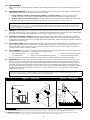
2.6 SWING FALLS: Swing Falls occur when the anchorage point is not directly above the point where the fall occurs (see
Figure 2). The force of striking an object while swinging from the pendulum effects of a Swing Fall can cause serious
injury. Swing Falls can be minimized by limiting the horizontal distance between the user and the anchorage point. In a
Swing Fall, the total vertical fall distance will be greater than if the user had fallen directly below the anchorage point,
thus increasing Fall Clearance required to safely arrest the user’s fall. See the PFAS manufacturer’s instructions for details
regarding Swing Falls and Fall Clearance calculation. If a Swing Fall hazard exists in your application, contact Capital
Safety before proceeding.
SRL SWING FALLS: In the event of a fall, and SRL will activate (lock up) regardless of the SRL’s orientation and location relative
to the user’s position; however, a common guideline is not to extend the work zone beyond 30° from the anchorage point. (The
Rooftop Anchor swivels allowing a 30° work area on all sides of the Rooftop Anchor.
Figure 2 – Swing Falls Figure 3 – Sharp Edges
Unexpected Hazards
Swing Fall Hazard
Sharp Edge
covered
with
Protective
Material
Sharp Edge
Approved SRL
1 Certifi ed Anchorage: An anchorage for Fall Arrest, Positioning, Restraint, or Rescue systems that a Qualifi ed Person certifi es to be capable of supporting the
potential fall forces that could be encountered during a fall or that meet the criteria for a certifi ed anchorage prescribed in the ANSI Z359 standards.
2 Competent Person: One who is capable of identifying existing and predictable hazards in the surroundings or working conditions which are unsanitary,
hazardous, or dangerous to employees, and who has authorization to take prompt corrective measures to eliminate them.

5
2.7 SHARP EDGES: Avoid working where Lifeline or Lanyard components of the Personal Fall Arrest System (PFAS) can
contact or abrade against unprotected sharp edges (see Figure 3). Where contact with a sharp edge is unavoidable, use
fall arrest equipment that is approved for sharp edge applications or cover the edge with protective material.
2.8 ENVIRONMENTAL HAZARDS: Use of this equipment in areas with environmental hazards may require additional
precautions to prevent injury to the user or damage to the equipment. Hazards may include, but are not limited to; heat,
chemicals, corrosive environments, high voltage power lines, explosive or toxic gases, moving machinery, and sharp
edges.
2.9 COMPONENT COMPATIBILITY: Capital Safety equipment is designed for use with Capital Safety approved components
and subsystems only. Substitutions or replacements made with non-approved components or subsystems may jeopardize
compatibility of equipment and may effect the safety and reliability of the complete system.
IMPORTANT: Equipment substitutions require written consent from Capital Safety.
2.10 CONNECTOR COMPATIBILITY: Connectors are considered to be compatible with connecting elements when they
have been designed to work together in such a way that their sizes and shapes do not cause their gate mechanisms
to inadvertently open regardless of how they become oriented. Contact Capital Safety if you have any questions about
compatibility.
Connectors (hooks, carabiners, and D-rings) must be capable of supporting at least 5,000 lbs. (22.2 kN). Connectors
must be compatible with the anchorage or other system components. Do not use equipment that is not compatible. Non-
compatible connectors may unintentionally disengage (see Figure 4). Connectors must be compatible in size, shape, and
strength. Self-locking snap hooks and carabiners are required by ANSI Z359 and OSHA.
2.11 MAKING CONNECTIONS: Snap hooks and carabiners used with this equipment must be self-locking. Ensure all
connections are compatible in size, shape and strength. Do not use equipment that is not compatible. Ensure all
connectors are fully closed and locked.
Capital Safety connectors (snap hooks and carabiners) are designed to be used only as specifi ed in each product’s user’s
instructions. See Figure 5 for examples of inappropriate connections. Do not connect snap hooks and carabiners:
A. To a D-ring to which another connector is attached.
B. In a manner that would result in a load on the gate.
NOTE: Large throat snap hooks should not be connected to standard size D-rings or similar objects which will
result in a load on the gate if the hook or D-ring twists or rotates, unless the snap hook complies is equipped with
a 3,600 lb (16 kN) gate. Check the marking on your snap hook to verify that it is appropriate for your application.
C. In a false engagement, where features that protrude from the snap hook or carabiner catch on the anchor, and
without visual confi rmation seems to be fully engaged to the anchor point.
D. To each other.
E. Directly to webbing or rope lanyard or tie-back (unless the manufacturer’s instructions for both the lanyard and
connector specifi cally allows such a connection).
F. To any object which is shaped or dimensioned such that the snap hook or carabiner will not close and lock, or that
roll-out could occur.
G. In a manner that does not allow the connector to align properly while under load.
Figure 4 – Unintentional Disengagement Figure 5 – Inappropriate Connections
If the connecting element to which a snap hook (shown) or carabiner attaches
is undersized or irregular in shape, a situation could occur where the connecting
element applies a force to the gate of the snap hook or carabiner. This force may
cause the gate (of either a self-locking or a non-locking snap hook) to open,
allowing the snap hook or carabiner to disengage from the connecting point.
Small ring or other
non-compatibly
shaped element
Force is applied to the
Snap Hook.
The Gate presses against
the Connecting Ring.
The Gate opens allowing
the Snap Hook to slip off.
A. B. C. D.
E. F. G.

6
3.0 INSTALLATION & USE
IMPORTANT: Do not alter or intentionally misuse this equipment. Consult Capital Safety when installing or using this equipment in
combination with components or subsystems other than those described in this manual. Some subsystems and component combinations
may interfere with the operation of this equipment.
3.1 SITE PLAN: Prior to roof construction, a site plan should be established which defi nes where the Rooftop Anchors will
be installed (see Figure 6) and how they may be used. In addition to the requirements defi ned in Section 2, the site plan
should take into account the following considerations:
• Structure: Structure on which the Rooftop Anchor is installed must meet or exceed the ‘Anchorage Strength’
requirement stated in Section 2.
• Fall Protection System: The Standing Seam Rooftop Anchor has been tested for use in the Fall Protection Systems
illustrated in Table 1. Depending on location of the Rooftop Anchor(s) on the roof deck, the Fall Protection System is
used in a Restraint
1
or Fall Arrest
2
application. For Restraint applications, the Rooftop Anchor(s) must be located on
the roof deck where they prevent the user from reaching any fall hazard (roof edge, access doorway, etc.).
TIP-OVER LOAD: The Rooftop Anchor can sustain loads to approximately 674 - 719 lbs (3.0 - 3.2 kN) before it starts to deploy
(tip over). In Restraint applications signifi cant force applied to the Rooftop Anchor may cause tip-over without an actual fall; in
which case, the Rooftop Anchor must be removed from service and replaced.
• Roof Type: The Standing Seam Rooftop Anchor shall only be mounted on fl at roofs or sloped roofs not exceeding
3:12 pitch. Roof Panels must meet the criteria listed in Table 2.
• Seam Clamps: Rooftop Anchors shall only be attached to the roof deck with the Seam Clamps defi ned in Table 1 for
your fall protection system and roof type.
• Anchor Position: The Rooftop Anchor must only be used in an upright position relative to the angle of the roof.
• Roof Support: Do not install the Rooftop Anchor on unsupported roof structures such as overhangs.
IMPORTANT: Use of the Rooftop Anchor with fall protection systems, roof types, or fasteners other than defi ned in Table 3 must be
approved by Capital Safety.
Figure 6 – Roof Anchor Site Plan - Anchor Locations
3.2 INSTALLATION: The Rooftop Anchor is designed for use on Standing Seam Metal Roofs meeting the requirements
defi ned in Table 1. Supported Personal Fall Arrest Systems (PFAS) and required Seam Clamps for securing the
Rooftop Anchor to the metal roof are also defi ned in Table 1.
IMPORTANT: Use of PFAS or fasteners other than recommended in Table 1 must be approved by Capital Safety.
Figure 7 illustrates installation of the Rooftop Anchor on a Standing Seam Metal Roof. Inspect Rooftop Anchors prior to
installation (see Table 3) and install all anchors in accordance with an approved Site Plan (see Section 3.1). To install the
Rooftop Anchor:
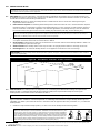
1. Install the required Seam Clamps (Table 1) on each corner of the Rooftop Anchor Mounting Plate:
HORIZONTAL SEAMS: Installation on Horizontal Seams narrower than 0.5 in. (12.7 mm)
requires “E” Seam Clamps in a vertical orientation. Installation on Horizontal Seams 0.5 in (12.7
mm) to 0.65 in (16.5 mm) wide requires “U” Seam Clamps in a vertical orientation. Installation
of the Rooftop Anchor on Horizontal Seams wider than 0.65 in. (16.5 mm) requires positioning
of the “U” Seam Clamps horizontally with the Setscrew(s) accessible from the top for tightening.
When installing Seam Clamps horizontally, the Seam Clamps should be positioned properly on
the roof seams (Step 2) and the Setscrews tightened to their required torque values (Step 3)
before securing the Seam Clamps to the Rooftop Anchor Mounting Plate (Step 1).
S<.5” .5”≤S≥.65” S>.65”
S
E
S
U
S
U
1 Restraint: The technique of securing an authorized person to an anchorage using a lanyard/lifeline short enough to prevent the person’s center of gravity from
reaching the fall hazard.
2 Fall Arrest: The action or event of stopping a free fall or the instant where the downward free fall has been stopped.

7
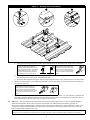
Figure 7 – Rooftop Anchor Installation
1 2
3
A. Remove the Mounting Bolt from the Seam Clamp and reposition the Setscrews in the proper holes if necessary.
SETSCREWS: On Folded Standing
Seams, the Seam Clamp Setscrews
should be positioned opposite the open
(overlap) side of the seam. On Horizontal
Seams wider than 0.65 in. (16.5 mm),
the Seam Clamp Setscrews should be
accessible from the top of the clamp.
“Z” SEAM CLAMPS: The “Z”
Seam Clamps used on Bulb Type
Standing Seams include an Insert
Shim. The Insert Shim should be
removed prior to installation of the
Clamp on the Bulb Type Standing
Seam.
B. Position the Seam Clamp on the bottom of the Mounting Plate so the mounting hole on the Seam Clamp aligns
with the largest hole in the corner of the Mounting Plate.
C. Thread the Mounting Bolt through the hole in the Mounting Plate and into the mounting hole on the Seam Clamp.
2. Position the Seam Clamps on two adjacent Roof Seams so the Rooftop Anchor is located at the position indicated on
the Site Plan (Figure 6).
“Z” SEAM CLAMPS: When “Z”
Seam Clamps are used to secure the
Rooftop Anchor to Bulb Type Standing
Seams, slide the Insert Shims between
seam and the Seam Clamp until the Insert
Shim aligns with the body of the Seam
Clamp.
3. Tighten all Mounting Plates and Setscrews to the torque values specifi ed in Table 1. A 3/16” Allen Bit is provided with
each Seam Clamp for tightening the Setscrews. For accurate torque values, the manufacturer recommends using a
Dial-Calibraed Torque Wrench (rather than a Clicking Torque Wrench).
3.3 USE: Table 1 lists and illustrates the Personal Fall Arrest Systems (PFAS) approved for use with the Rooftop Standing
Seam Metal Roof Anchor. Refer to the instructions included with your PFAS equipment for details regarding use.
In the event of a fall, Internal Supports inside the anchor Can break away allowing the Tip Over Element to bend. Figure
8 illustrates a deployed Rooftop Anchor. Once deployed, the Roof Anchor reduces the moment load on the roof so the
anchor remains safely attached to the roof.
IMPORTANT: If the Rooftop Anchor is exposed to fall forces and deploys, remove it from service immediately and replace. Do not
attempt to repair the Rooftop Anchor Inspect the roof for signs of damage or structural weakening before installing the new anchor.

8
Figure 8 – Rooftop Anchor Deployment
Normal
Deployed
4.0 INSPECTION
4.1 INSPECTION FREQUENCY: The Rooftop Anchor must be inspected at the intervals defi ned in Section 1. Inspection
procedures are described in the “Inspection and Maintenance Log” (Table 3). Inspect all other components of the Fall
Protection System per the frequencies and procedures defi ned in the manufacturer’s instructions.
4.2 DEFECTS: If inspection reveals an unsafe or defective condition, remove the Rooftop Anchor from service immediately
and replace. Do not attempt to repair the Rooftop Anchor.
4.3 PRODUCT LIFE: The functional life of the Rooftop Anchor is determined by work conditions and maintenance. As long as
the product passes inspection criteria, it may remain in service.
5.0 MAINTENANCE, SERVICING, STORAGE
5.1 CLEANING: Periodically clean The Rooftop Anchor with a soft brush, warm water, and a mild soap solution. Ensure parts
are thoroughly rinsed with clean water.
IMPORTANT: Although highly resistant to chemicals and environmental conditions, avoid contaminating the Rooftop Anchor with
acids, bitumen, cement, paint, cleaning fl uids, etc. If the Rooftop Anchor contacts acids or other caustic chemicals, remove from service
and wash with water and a mild soap solution. Inspect per Table 3 before returning to service.
5.2 SERVICE: The Rooftop Anchor is not repairable. If the anchor has been subject to fall force or inspection reveals an
unsafe or defective conditions, remove the anchor from service and replace with another Rooftop Anchor.
IMPORTANT: Only Capital Safety or parties authorized in writing may make repairs to this equipment.
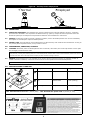
6.0 SPECIFICATIONS & LABELING
B
A
C
D
Component Materials Weight
A
Can Steel, Powder Coated 0.66 lbs (0.3 kg)
B
Eye Stainless Steel 1.0 lbs (0.46 kg)
C
Mounting Plate Steel, Powder Coated 8.1 lbs (3.69 kg)
Max. Allowable Fall Arrest Load: 1,800 lbs (8 kN) Max. Allowable HLL System Load: 2,500 lbs (11.1 kN)
D

9
Dimensions:
Ø 0.32” (8.2 mm)
Ø 0.41” (10.5 mm)
17.32” (440 mm)
16.00” (400 mm)
13.78” (350 mm)
12.00” (300 mm)
10.16” (258 mm)
0.12” (3 mm)

Table 3 – Inspection and Maintenance Log
Serial Number(s): Date Purchased:
Model Number: Date of First Use:
Inspection Date: Inspected By:
Component: Inspection: (See Section 1 for Inspection Frequency) User
Competent
Person
Rooftop Anchor Visually inspect the Rooftop Anchor for physical damage. Look for cracks,
dents, or deformities in the metal.
Visually inspect the Rooftop Anchor for excessive corrosion.
Inspect the Eye for proper operation. Verify that the the Nut securing the
Eye is tight and the Eye rotates freely 360° around the top of the anchor.
Verify that the Rooftop Anchor has not deployed. If the Rooftop Anchor
has deployed, remove the anchor from service immediately and replace.
Inspect the roof for signs of damage or structural weakening before
installing the new anchor.
Seam Clamps Visually inspect the Seam Clamps for physical damage. Look for cracks,
dents, or deformities in the metal.
Pull up on the Rooftop Anchor Mounting Plate to verify that all four Seam
Clamps are secure on the Mounting Plate and are clamped securely to the
roof seams. If the Seam Clamps feel loose, tighten the Mounting Bolts and
Setscrews to the torque values specifi ed in Table 1.
Tighten Mounting Bolts and Setscrews on all Seam Clamps to the torque
values specifi ed in Table 1.
Label Verify that the label is securely attached to the Rooftop Anchor and it is
fully legible (see Section 6).
Fall Protection
Equipment
Inspect all other Fall Protection Equipment used with the Rooftop Anchors
(Harness, SRL, lanyard, etc.) per the manufacturer’s instructions.
Corrective Action/Maintenance: Approved By:
Date:
Corrective Action/Maintenance: Approved By:
Date:
Corrective Action/Maintenance: Approved By:
Date:
Corrective Action/Maintenance: Approved By:
Date:
Corrective Action/Maintenance: Approved By:
Date:
Corrective Action/Maintenance: Approved By:
Date:
Corrective Action/Maintenance: Approved By:
Date:
Corrective Action/Maintenance: Approved By:
Date:
Corrective Action/Maintenance: Approved By:
Date:
Corrective Action/Maintenance: Approved By:
Date:
Corrective Action/Maintenance: Approved By:
Date:
Corrective Action/Maintenance: Approved By:
Date:

LIMITED LIFETIME WARRANTY
Warranty to End User: D B Industries, Inc., dba CAPITAL SAFETY USA (“CAPITAL SAFETY”)
warrants to the original end user (“End User”) that its products are free from defects in materials and
workmanship under normal use and service. This warranty extends for the lifetime of the product
from the date the product is purchased by the End User, in new and unused condition, from a CAPITAL
SAFETY authorized distributor. CAPITAL SAFETY’S entire liability to End User and End User’s exclusive
remedy under this warranty is limited to the repair or replacement in kind of any defective product
within its lifetime (as CAPITAL SAFETY in its sole discretion determines and deems appropriate). No oral
or written information or advice given by CAPITAL SAFETY, its distributors, directors, offi cers, agents
or employees shall create any different or additional warranties or in any way increase the scope of
this warranty. CAPITAL SAFETY will not accept liability for defects that are the result of product abuse,
misuse, alteration or modifi cation, or for defects that are due to a failure to install, maintain, or use the
product in accordance with the manufacturer’s instructions.
CAPITAL SAFETY’S WARRANTY APPLIES ONLY TO THE END USER. THIS WARRANTY IS THE ONLY
WARRANTY APPLICABLE TO OUR PRODUCTS AND IS IN LIEU OF ALL OTHER WARRANTIES AND
LIABILITIES, EXPRESSED OR IMPLIED. CAPITAL SAFETY EXPRESSLY EXCLUDES AND DISCLAIMS
ANY IMPLIED WARRANTIES OF MERCHANTABILITY OR FITNESS FOR A PARTICULAR PURPOSE, AND
SHALL NOT BE LIABLE FOR INCIDENTAL, PUNITIVE OR CONSEQUENTIAL DAMAGES OF ANY NATURE,
INCLUDING WITHOUT LIMITATION, LOST PROFITS, REVENUES, OR PRODUCTIVITY, OR FOR BODILY
INJURY OR DEATH OR LOSS OR DAMAGE TO PROPERTY, UNDER ANY THEORY OF LIABILITY, INCLUDING
WITHOUT LIMITATION, CONTRACT, WARRANTY, STRICT LIABILITY, TORT (INCLUDING NEGLIGENCE) OR
OTHER LEGAL OR EQUITABLE THEORY.
GARANTIE LIMITÉE SUR LA DURÉE DE VIE
Garantie offerte à l’utilisateur fi nal : D B Industries, Inc., dba CAPITAL SAFETY USA (« CAPITAL SAFETY »)
garantit à l’utilisateur fi nal d’origine (« Utilisateur fi nal ») que les produits sont libres de tout défaut matériel et de
fabrication dans des conditions normales d’utilisation et de service. Cette garantie couvre toute la durée de vie du
produit, de sa date d’achat à l’état neuf et inutilisé par l’utilisateur auprès d’un distributeur agréé CAPITAL SAFETY.
La responsabilité intégrale de Capital Safety et le seul recours du Client dans le cadre de cette garantie se limitent
à la réparation ou le remplacement en nature des produits défectueux pendant leur durée de vie (à la seule
discrétion de Capital Safety et selon ce qu’elle juge approprié). Aucun renseignement ou avis oral ou écrit fourni par
CAPITAL SAFETY, ses détaillants, administrateurs, cadres, distributeurs, mandataires ou employés ne représentera
une garantie ou n’augmentera de quelque manière la portée de la présente garantie limitée. CAPITAL SAFETY
n’accepte aucune responsabilité pour les défauts causés par un abus, une utilisation abusive, une altération ou une
modifi cation, ou pour les défauts causés par le non-respect des instructions du fabricant relatives à l’installation,
à l’entretien ou à l’utilisation du produit.
CETTE GARANTIE CAPITAL SAFETY S’APPLIQUE UNIQUEMENT À L’UTILISATEUR FINAL. ELLE EST LA SEULE
GARANTIE APPLICABLE À NOS PRODUITS. ELLE EXCLUT TOUTE AUTRE GARANTIE EXPRESSE OU IMPLICITE.
CAPITAL SAFETY EXCLUT EXPLICITEMENT ET DÉCLINE TOUTE GARANTIE IMPLICITE DE MISE EN MARCHÉ ET
D’ADAPTATION À DES FINS PARTICULIÈRES, ET NE SERA RESPONSABLE POUR AUCUN DOMMAGE-INTÉRÊT
DIRECT OU INDIRECT, CORRÉLATIF OU ACCESSOIRE DE TOUTE NATURE Y COMPRIS ET DE MANIÈRE NON
LIMITATIVE, LES PERTES DE PROFITS, LES REVENUS OU LA PRODUCTIVITÉ, LES BLESSURES CORPORELLES,
VOIRE LA MORT OU DOMMAGES À LA PROPRIÉTÉ, DANS LE CADRE DE TOUTE THÉORIE DE RESPONSABILITÉ, Y
COMPRIS ET DE MANIÈRE NON LIMITATIVE UN CONTRAT, UNE GARANTIE, UNE RESPONSABILITÉ (Y COMPRIS LA
NÉGLIGENCE) OU TOUTE AUTRE THÉORIE LÉGALE OU ÉQUITABLE.

ISO
9001
CSG USA & Latin America
3833 SALA Way
Red Wing, MN 55066-5005
Toll Free: 800.328.6146
Phone: 651.388.8282
Fax: 651.388.5065
solutions@capitalsafety.com
CSG Canada
260 Export Boulevard
Mississauga, ON L5S 1Y9
Phone: 905.795.9333
Toll-Free: 800.387.7484
Fax: 888.387.7484
info.ca@capitalsafety.com
CSG Northern Europe
5a Merse Road
North Moons, Moat
Reditch, Worcestershire, UK
B98 9HL
Phone: + 44 (0)1527 548 000
Fax: + 44 (0)1527 591 000
csgne@capitalsafety.com
CSG EMEA
(Europe, Middle East, Africa)
Le Broc Center
Z.I. 1ère Avenue
5600 M B.P. 15 06511
Carros
Le Broc Cedex
France
Phone: + 33 4 97 10 00 10
Fax: + 33 4 93 08 79 70
information@capitalsafety.com
CSG Australia & New Zealand
95 Derby Street
Silverwater
Sydney NSW 2128
AUSTRALIA
Phone: +(61) 2 8753 7600
Toll-Free : 1 800 245 002 (AUS)
Toll-Free : 0800 212 505 (NZ)
Fax: +(61) 2 87853 7603
sales@capitalsafety.com.au
CSG Asia
Singapore:
16S, Enterprise Road
Singapore 627666
Phone: +65 - 65587758
Fax: +65 - 65587058
inquiry@capitalsafety.com
Shanghai:
Rm 1406, China Venturetech Plaza
819 Nan Jing Xi Rd,
Shanghai 200041, P R China
Phone: +86 21 62539050
Fax: +86 21 62539060
www.capitalsafety.com
The Ultimate in Fall Protection
-
 1
1
-
 2
2
-
 3
3
-
 4
4
-
 5
5
-
 6
6
-
 7
7
-
 8
8
-
 9
9
-
 10
10
-
 11
11
-
 12
12


3M DBI-SALA® Roof Top Anchor 2100138, 1 EA Mode d'emploi
- Taper
- Mode d'emploi
dans d''autres langues
Documents connexes
-
3M DBI-SALA® Window and Door Jamb Anchor 2100080, 1 EA Mode d'emploi
-
-
-
-
-
-
-
-
-