Kichler Lighting 42494CH Manuel utilisateur
- Taper
- Manuel utilisateur

Date Issued: 08/09/17 IS-42494-US
We’re here to help 866-558-5706
Hrs: M-F 9am to 5pm EST
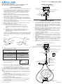
CAUTION – RISK OF SHOCK –
Disconnect Power at the main circuit breaker panel or main
fuse box before starting and during the installation.
1) Select proper length of stem(s) required. Pass wire through short
threaded nipple and thread into coupling at top of fixture us-
ing thread locking compound. Thread stem(s) onto nipple using
thread locking compound. Continue with remaining stem(s).
Thread small nipple into top of last stem (ceiling side) using
thread locking compound.
2) NOTE: Thread locking compound must be applied to all stem
threads as noted with symbol to prevent accidental rotation of
stems during cleaning, relamping, etc
3) Pass fixture wires thru hole in canopy. Make sure open side of
canopy faces ceiling. Pass threaded nipple of stem thru hole in
canopy. Slip lockwasher over end of nipple. Thread hexnut onto
end of stem. Tighten to secure.
4) Find the appropriate threaded holes on mounting strap. Assemble
mounting screws into threaded holes.
5) Attach mounting strap to outlet box. Mounting strap can be ad-
justed to suit position of fixture.
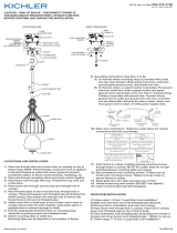
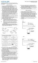
6) Grounding instructions: (See Illus. A or B)
A) On fixtures where mounting strap is provided with a
hole and two raise dimples. Wrap ground wire from
outlet box around green ground screw, and thread into
hole.
B) On fixtures where a cupped washer is provided. Put
ground wire from outlet box under cupped washer and
green ground screw and thread screw into hole in
mounting strap.
If fixture is provided with ground wire. Connect fixture ground wire
to outlet box ground wire with wire connector, after following the
above steps. Never connect ground wire to black or white power
supply wires.
7) Make wire connections. Reference chart below for correct con-
nections and wire accordingly.
8) Push fixture to ceiling, carefully passing mounting screws through
holes in canopy. Make sure all wires are inside canopy and do
not get pinched between canopy and ceiling.
9) Slip lockwashers over mounting screws. Thread lockup knobs
onto mounting screw and tighten to secure fixture to ceiling
Read all of the remaining steps before installing the remaining
arms:
10) Slip the upper end of a support arm into a hole in the upper hous-
ing. Slip the bottom of the arm into a hole in the bottom of the
socket housing.
11) Using the allen wrench (supplied), screw the top part of the arm
into the housing with a set screw. Tighten to secure.
12) Screw the bottom part of the arm into the side of the socket
housing. Tighten to secure.
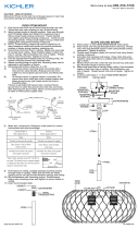
13) Insert recommended bulb (Not supplied).
14) Carefully place glass over the bulb and then rest the glass onto
the arms. (the lip should be on the inside of the glass). HOLD
GLASS IN PLACE.
15) Repeat steps 10 through 12 for installing the third arm.
GREEN GROUND
SCREW
CUPPED
WASHER
OUTLET BOX
GROUND
FIXTURE
GROUND
DIMPLES
WIRE CONNECTOR
OUTLET BOX
GROUND
GREEN GROUND
SCREW
FIXTURE
GROUND
A
B
Connect Black or
Red Supply Wire to:
Connect
White Supply Wire to:
Black White
*Parallel cord (round & smooth) *Parallel cord (square & ridged)
Clear, Brown, Gold or Black
without tracer
Clear, Brown, Gold or Black
with tracer
Insulated wire (other than green)
with copper conductor
Insulated wire (other than green)
with silver conductor
*Note: When parallel wires (SPT I & SPT II)
are used. The neutral wire is square shaped
or ridged and the other wire will be round in
shape or smooth (see illus.)
Neutral Wire
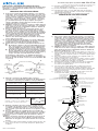
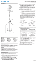
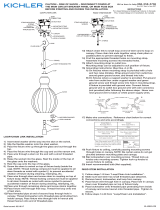
RIGID STEM MOUNT
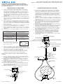
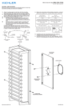
SLOPE CEILING MOUNT
1) Select proper length of stem(s) required. Pass wire through
short threaded nipple and thread into coupling at top of fixture
using thread locking compound. Thread stem(s) onto nipple
using thread locking compound. Continue with remaining
stem(s). Thread small nipple into top of last stem (ceiling side)
using thread locking compound.
2) NOTE: Thread locking compound must be applied to all stem
threads as noted with symbol to prevent accidental rotation of
stems during cleaning, relamping, etc
3) Pass fixture wire through threaded hole in first loop. Thread
loop onto last threaded nipple in stem using thread locking
compound. Tighten to secure.
4) Thread small threaded nipple into second loop using thread
locking compound.
5) Add chain link between both loops. Close chain link ends to-
gether using chain pliers or padded pliers to prevent damage
to finish.
6) Weave fixture wire thru chain link and second loop and pass
thru threaded nipple in second loop.
7) Make sure open side of canopy faces ceiling. Pass threaded
nipple of loop thru hole in canopy. Slip lockwasher over end
of nipple. Thread hexnut onto end of nipple. Tighten to se-
cure.
8) Continue with steps 4 through 15 from RIGID STEM MOUNT
instructions.
RIGID STEM MOUNT
SMALL THREADED PIPE
TUBO ROSCADO PEQUEÑO
LOCK-UP KNOBS
PERILLAS DE SUJECIÓN
LOCKWASHERS
ARANDELA DE SEGURIDAD
STEM(S)
VÁSTAGO
OUTLET BOX
CAJA DE SALIDA
WIRE CONNECTORS
CONECTORES DE ALAMBRE
STRAP MOUNTING SCREWS
TORNILLOS DE MONTAJE
DE LA ABRAZADERA
HEXNUT / TUERCA HEXAGONAL
LOCKWASHER / ARANDELA DE SEGURIDAD
THREAD LOCKING COMPOUND
COMPUESTO PARA ROSCA ESTANCA
STEM(S)
VÁSTAGO
SHORT THREADED PIPE
TUBO ROSCADO CORTO
►
MOUNTING SCREWS / TORNILLO DE MONTAJE
OUTLET BOX
CAJA DE SALIDA
WIRE CONNECTORS
CONECTORES DE ALAMBRE
STRAP MOUNTING SCREWS
TORNILLOS DE MONTAJE
DE LA ABRAZADERA
MOUNTING STRAP / ABRAZADERA DE MONTAJE
CANOPY / ESCUDETE
LOCK-UP KNOBS / PERILLAS DE SUJECIÓN
LOCKWASHERS / ARANDELA DE SEGURIDAD
LOOP
ANILLO
CHAIN LINK
ESLABÓN DE CADENA
HEXNUT / TUERCA HEXAGONAL
LOCKWASHER / ARANDELA DE SEGURIDAD
SMALL THREADED PIPE / TUBO ROSCADO PEQUEÑO
►
ALLEN WRENCH
LLAVE ALLEN
ALLEN WRENCH
LLAVE ALLEN
GLASS
VIDRIO
(3) SUPPORT ARM
BRAZOS DE APOYO
SOCKET
PORTALÁMPARAS
COUPLING
ACOPLAMIENTO
UPPER HOUSING
ALOJAMIENTO SUPERIOR
SET SCREW
TORNILLO DE AJUSTE
SET SCREW
TORNILLO DE AJUSTE

Date Issued: 08/09/17 IS-42494-US
Estamos aquí para ayudarle 866-558-5706
Horario: Lunes-Viernes 9am a 5pm EST (hora oficial del este)
1) Seleccione el largo apropiado del vástago o los vástagos
requeridos. Pase el cable a través del niple roscado corto
y enrosque en el acoplamiento en la parte superior del ar-
tefacto, usando compuesto para rosca estanca. Enrosque
el vástago o los vástagos en el niple usando compuesto
para rosca estanca. Continúe con el vástago o los vásta-
gos restantes. Enrosque el niple pequeño en la parte
superior del último vástago (del lado del techo) usando
compuesto para rosca estanca.
2) NOTA: El compuesto para rosca estanca se debe aplicar a
todas las roscas de los vástagos indicadas con el símbolo
para evitar la rotación accidental del artefacto durante la
limpieza, cambio de foco, etc.
3) Pase los cables del artefacto a través del agujero en el
escudete. Cerciórese que el lado abierto del escudete
mire al techo. Pase el niple roscado del vástago a través
del agujero en el escudete. Pase la arandela de seguridad
sobre el extremo del niple. Enrosque la tuerca hexagonal
en el extremo del vástago. Apriete para asegurar.
4) Encuentre los agujeros roscados apropiados en la
abraza- dera de montaje. Monte los tornillos de montaje
en los agujeros roscados.
5) Acople la abrazadera de montaje a la caja de salida. (No
se provee tornillos). La abrazadera de montaje se puede
ajustar para acomodar la posición del artefacto.
6) Instrucciones de conexión a tierra (Vea la ilustración A o
B)
A) En artefactos donde se provee la abrazadera de mon
taje con un agujero y dos depresiones onduladas: En
vueva el alambre de tierra de la caja de salida alred
edor del tornillo de tierra verde y rosque en el agujero.
B) En artefactos donde se provee una arandela cóncava.
Acople el alambre de tierra de la caja de salida debajo
de la arandela cóncava y del tornillo de tierra verde, y
rosque el tornillo en la abrazadera de montaje.
Si el artefacto está provisto con alambre de tierra: Co-
necte el alambre de tierra del artefacto con el alambre de
tierra de la caja de salida con un conector de alambre. (No
se provee.)
7) Haga las conexiones de alambres (No se provee
conecto- res). Vea la tabla de referencia de abajo para las
conexiones correctas y los alambres correspondientes.
8) Empuje el artefacto al techo, pasando cuidadosamente
los tornillos de montaje a través de los agujeros en el
escudete. Confirme que todos los cables queden dentro
del escudete, y que el borde de éste no los apriete contra
el techo.
9) Pase las arandelas de seguridad sobre los tornillos de
montaje. Enrosque las perillas de sujeción en los tornillos
de montaje, y apriete para asegurar el artefacto al techo.
Lea todos los pasos restantes antes de instalar los brazos
restantes:
10) Deslice el extremo superior de un brazo de soporte en un
agujero en la carcasa superior. Deslice la parte inferior
del brazo en un agujero en la parte inferior de la caja del
zócalo.
11) Con la llave allen (suministrada), atornille la parte superior del
brazo en la carcasa con un tornillo de fijación. Apriete para
asegurar.
PRECAUCIÓN – RIESGO DE DESCARGA ELÉCTRICA –
Desconecte la electricidad en el panel principal del interruptor
automático o caja principal de fusibles antes de comenzar y
durante la instalación.
ARANDELA
CONCAVA
TIERRA DE LA
CAJA DE SALIDA
TORNILLO DE TIERRA,
VERDE
DEPRESIONES
TIERRA
ARTEFACTO
CONECTOR DE ALAMBRE
TIERRA DE LA
CAJA DE SALIDA
TORNILLO DE TIERRA,
VERDE
TIERRA
ARTEFACTO
A
B
Conectar el alambre de
suministro negro o rojo al
Conectar el alambre de
suministro blanco al
Negro Blanco
*Cordon paralelo (redondo y liso)
*Cordon paralelo (cuadrado y estriado)
Claro, marrón, amarillio o negro
sin hebra identificadora
Claro, marrón, amarillio o negro
con hebra identificadora
Alambre aislado (diferente del verde)
con conductor de cobre
Alambre aislado (diferente del
verde) con conductor de plata
*Nota: Cuando se utiliza alambre paralelo
(SPT I y SPT II). El alambre neutro es de forma
cuadrada o estriada y el otro alambre será de
forma redonda o lisa. (Vea la ilustracíón).
Hilo Neutral
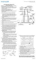
MONTAJE DEL VÁSTAGO RÍGIDO
MONTAJE DEL VÁSTAGO RÍGIDO
SLOPE CEILING MOUNT
1) Seleccione el largo apropiado del vástago o los vástagos
requeridos. Pase el cable a través del niple roscado corto
y enrosque en el acoplamiento en la parte superior del ar-
tefacto, usando compuesto para rosca estanca. Enrosque
el vástago o los vástagos en el niple usando compuesto
para rosca estanca. Continúe con el vástago o los vásta-
gos restantes. Enrosque el niple pequeño en la parte
superior del último vástago (del lado del techo) usando
compuesto para rosca estanca.
2) NOTA: El compuesto para rosca estanca se debe aplicar a
todas las roscas de los vástagos indicadas con el símbolo
para evitar la rotación accidental del artefacto durante la
limpieza, cambio de foco, etc.
3) Pase el cable del artefacto a través del agujero roscado en el
primer anillo. Enrosque el anillo en el último niple roscado en el
vástago, usando compuesto para rosca estanca. Apriete para
asegurar.
4) Enrosque el niple roscado pequeño en el segundo anillo, us-
ando compuesto para rosca estanca.
5) Añada un eslabón de cadena entre los anillos. Cierre los extre-
mos de los eslabones de cadena, usando pinza para cadena o
pinza acolchada para evitar daño al acabado.
6) Armadura del luminario al alambre a través del acoplamiento
de cadena y el segundo bucle y pasar a través de niple
roscado en el segundo bucle.
7) Cerciórese que el lado abierto del escudete mire al techo.
Pase el niple roscado del anillo a través del agujero en el
escudete. Pase la arandela de seguridad sobre el extremo del
niple. Enrosque la tuerca hexagonal en el extremo del niple.
Apriete para asegurar.
8) Continuar con los pasos 4 through 15 de instrucciones de
montaje de tallo rígido.
12) Atornille la parte inferior del brazo en el lado de la caja del
zócalo. Apriete para asegurar.
13) Inserte la bombilla recomendada (no suministrada).
14) Carefully place glass over the bulb and then rest the glass
onto the arms. (the lip should be on the inside of the glass).
HOLD GLASS IN PLACE.
15) Repeat steps 10 through 12 for installing the third arm.
SMALL THREADED PIPE
TUBO ROSCADO PEQUEÑO
LOCK-UP KNOBS
PERILLAS DE SUJECIÓN
LOCKWASHERS
ARANDELA DE SEGURIDAD
STEM(S)
VÁSTAGO
OUTLET BOX
CAJA DE SALIDA
WIRE CONNECTORS
CONECTORES DE ALAMBRE
STRAP MOUNTING SCREWS
TORNILLOS DE MONTAJE
DE LA ABRAZADERA
HEXNUT / TUERCA HEXAGONAL
LOCKWASHER / ARANDELA DE SEGURIDAD
THREAD LOCKING COMPOUND
COMPUESTO PARA ROSCA ESTANCA
STEM(S)
VÁSTAGO
SHORT THREADED PIPE
TUBO ROSCADO CORTO
►
MOUNTING SCREWS / TORNILLO DE MONTAJE
OUTLET BOX
CAJA DE SALIDA
WIRE CONNECTORS
CONECTORES DE ALAMBRE
STRAP MOUNTING SCREWS
TORNILLOS DE MONTAJE
DE LA ABRAZADERA
MOUNTING STRAP / ABRAZADERA DE MONTAJE
CANOPY / ESCUDETE
LOCK-UP KNOBS / PERILLAS DE SUJECIÓN
LOCKWASHERS / ARANDELA DE SEGURIDAD
LOOP
ANILLO
CHAIN LINK
ESLABÓN DE CADENA
HEXNUT / TUERCA HEXAGONAL
LOCKWASHER / ARANDELA DE SEGURIDAD
SMALL THREADED PIPE / TUBO ROSCADO PEQUEÑO
►
ALLEN WRENCH
LLAVE ALLEN
ALLEN WRENCH
LLAVE ALLEN
GLASS
VIDRIO
(3) SUPPORT ARM
BRAZOS DE APOYO
SOCKET
PORTALÁMPARAS
COUPLING
ACOPLAMIENTO
UPPER HOUSING
ALOJAMIENTO SUPERIOR
SET SCREW
TORNILLO DE AJUSTE
SET SCREW
TORNILLO DE AJUSTE

Date Issued: 08/09/17 IS-42494-CB
Nous sommes là pour vous aider 866-558-5706
Heures : du lundi au vendredi, de 9h à 17h (heure de l’Est)
ATTENTION – RISQUE DE DÉCHARGES ÉLECTRIQUES -
Couper le courant au niveau du panneau du disjoncteur du
circuit principal ou de la boîte à fusibles principale avant de
procéder à l’installation.
1) Choisir les tiges de la longueur appropriée. Passer le fil à
travers le raccord fileté court et visser dans l’accouplement
sur le dessus du luminaire en utilisant un composé de ver-
rouillage fileté. Visser la(les) tiges dans le raccord en utilisant
un composé de verrouillage fileté. Continuer avec la(les)
tige(s) restante(s). Visser le petit raccord dans le dessus de
la dernière tige (côté plafond) en utilisant un composé de ver-
rouillage fileté.
2) NOTA: El compuesto para rosca estanca se debe aplicar a to-
das las roscas de los vástagos indicadas con el símbolo para
evitar la rotación accidental del artefacto durante la limpieza,
cambio de foco, etc.
3) Vous assurer que le côté ouvert du couvercle fait face au pla-
fond. Passer le raccord fileté de la tige à travers le trou dans
le couvercle. Glisser la rondelle de verrouillage sur l’extrémité
du raccord. Visser l’écrou hexagonal sur l’extrémité de la tige.
Serrer fermement.
4) Trouver les trous letés appropriés sur le support de mon- tage.
Visser les vis de montage dans les trous taraudés.
5) Fixer le support de montage sur la bo te à prises. Le support
de montage peut être réglé a n de positionner correctement le
luminaire.
6) Connecter les ls. Se porter au tableau ci-dessous pour faire
les connexions.
7) Pousser le luminaire contre le plafond, en passant avec soin
les vis de montage à travers les trous dans le couvercle. Vous
assurer que tous les fils sont dans le couvercle et ne se retrou-
vent pas pincés entre le couvercle et le plafond.
8) Glisser les rondelles de verrouillage par-dessus les vis de
montage. Visser les boutons de verrouillage sur les vis de
montage et serrer pour fixer le luminaire au plafond.
Lisez toutes les étapes restantes avant d’installer les bras
restants:
9) Glisser l’extrémité supérieure d’un bras de support dans un
trou dans le boîtier supérieur. Glissez le bas du bras dans un
trou dans le fond du boîtier de la douille.
10) En utilisant la clé allen (fournie), visser la partie supérieure
du bras dans le boîtier avec une vis de réglage. Serrez pour
sécuriser.
11) Vissez la partie inférieure du bras dans le côté du boîtier de la
douille. Serrez pour sécuriser.
12) Insérez l’ampoule recommandée (non fournie).
13) Placez soigneusement le verre sur l’ampoule, puis reposez
le verre sur les bras. (La lèvre doit être à l’intérieur du verre).
AVERTISSEMENT EN PLACE.
14) Répétez les étapes 10 à 12 pour installer le troisième bras.
Connect Black or
Red Supply Wire to:
Connect
White Supply Wire to:
Black White
*Parallel cord (round & smooth) *Parallel cord (square & ridged)
Clear, Brown, Gold or Black
without tracer
Clear, Brown, Gold or Black
with tracer
Insulated wire (other than green)
with copper conductor
Insulated wire (other than green)
with silver conductor
*Note: When parallel wires (SPT I & SPT II)
are used. The neutral wire is square shaped
or ridged and the other wire will be round in
shape or smooth (see illus.)
Neutral Wire
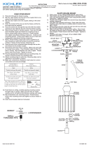
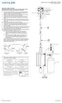
MONTAGE DE LA TIGE RIGIDE PENTE DE MONTAGE AU PLAFOND
1) Choisir les tiges de la longueur appropriée. Passer le fil à
travers le raccord fileté court et visser dans l’accouplement
sur le dessus du luminaire en utilisant un composé de ver-
rouillage fileté. Visser la(les) tiges dans le raccord en utilisant
un composé de verrouillage fileté. Continuer avec la(les)
tige(s) restante(s). Visser le petit raccord dans le dessus de
la dernière tige (côté plafond) en utilisant un composé de ver-
rouillage fileté.
2) NOTA: El compuesto para rosca estanca se debe aplicar a to-
das las roscas de los vástagos indicadas con el símbolo para
evitar la rotación accidental del artefacto durante la limpieza,
cambio de foco, etc.
3) Passer le fil du luminaire à travers le trou fileté de la première
boucle. Visser la boucle sur le dernier raccord fileté dans la
tige en utilisant un composé de verrouillage fileté. Serrer
fermement.
4) Visser le petit raccord fileté dans la deuxième boucle en util-
isant un composé de verrouillage fileté.
5) Ajouter un maillon de chaîne entre les deux boucles. Fermer
les maillons en utilisant des pinces régulières ou matelassées
pour prévenir les dommages au revêtement de la chaîne.
6) Tissent le fil de l’appareil par le biais de maillon de chaîne et
de la deuxième boucle et passer à travers un raccord fileté
dans la deuxième boucle.
7) Vous assurer que le côté ouvert du couvercle fait face au
plafond. Passer le raccord fileté de la boucle à travers le
trou dans le couvercle. Glisser la rondelle de verrouillage
sur l’extrémité du raccord. Visser l’écrou hexagonal sur
l’extrémité du raccord. Serrer fermement.
8) Poursuivez les étapes 4 vec 14 des instructions de montage
de tige rigide.
SMALL THREADED PIPE
PETIT TUBE FILTÉ
LOCK-UP KNOBS
BOULES DE BLOCAGE
LOCKWASHERS
RONDELLE DE BLOCAGE
STEM(S)
TIGE
OUTLET BOX
CAJA DE SALIDA
WIRE CONNECTORS
CONNECTEURS DE FIL
STRAP MOUNTING SCREWS
VIS DE L'ÉTRIER DE MONTAGE
HEXNUT / ÉCROU HEXAGONAL
LOCKWASHER / RONDELLE DE BLOCAGE
THREAD LOCKING COMPOUND
COMPOSÉ DE VERROUILLAGE FILETÉ
STEM(S)
TIGE
SHORT THREADED PIPE
TUBE FILTÉ
►
MOUNTING SCREWS / VIS DE MONTAGE
OUTLET BOX
BOÎTE À PRISES
WIRE CONNECTORS
CONNECTEURS DE FIL
STRAP MOUNTING SCREWS
VIS DE L'ÉTRIER DE MONTAGE
MOUNTING STRAP / ÉTRIER DE MONTAGE
CANOPY / COUVERCLE
LOCK-UP KNOBS / BOULES DE BLOCAGE
LOCKWASHERS / RONDELLE DE BLOCAGE
LOOP
BOUCLE
CHAIN LINK
MAILLON DE CHAÎNE
HEXNUT / ÉCROU HEXAGONAL
LOCKWASHER / RONDELLE DE BLOCAGE
SMALL THREADED PIPE / PETIT TUBE FILTÉ
►
ALLEN WRENCH
CLÉ ALLEN
ALLEN WRENCH
CLÉ ALLEN
GLASS
VERRE
(3) SUPPORT ARM
BRAS DE SUPPORT
SOCKET
DOUILLE
COUPLING
ACCOUPLEMENT
UPPER HOUSING
ALOJAMIENTO SUPERIOR
SET SCREW
VIS DE RÉGLAGE
SET SCREW / VIS DE RÉGLAGE
-
 1
1
-
 2
2
-
 3
3


Kichler Lighting 42494CH Manuel utilisateur
- Taper
- Manuel utilisateur
dans d''autres langues
Documents connexes
-
 Kichler Lighting 43954NI Manuel utilisateur
-
 Kichler Lighting 43869BK Manuel utilisateur
-
 Kichler Lighting 42496NI Manuel utilisateur
-
 Kichler Lighting 49785BKLED Manuel utilisateur
-
 Kichler Lighting 43958NBR Manuel utilisateur
-
 Kichler Lighting 43925NI Manuel utilisateur
-
 Kichler Lighting 43953NI Manuel utilisateur
-
 Kichler Lighting 44009MIZ Manuel utilisateur
-
 Kichler Lighting 43898OZ Manuel utilisateur
-
Kichler 6719NI Manuel utilisateur


