Dri-Eaz LGR 2800i Le manuel du propriétaire
- Catégorie
- Déshumidificateurs
- Taper
- Le manuel du propriétaire
Ce manuel convient également à

Owner’s Manual
LGR 2800i Portable Dehumidifier (F410)
LGR 3500i Portable Dehumidifier (F411)
DRI-EAZ PRODUCTS, INC.
15180 Josh Wilson Road, Burlington, WA 98233
Phone: 800-932-3030 Fax: 360-757-7950 www.dri-eaz.com
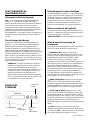
The Dri-Eaz® LGR i-Series dehumidifiers reduce humidity in enclosed structural
environments by removing water vapor from the air. The i-Series product line is engineered
to be rugged, durable and highly portable, making them ideally suited for water damage
restoration, structural drying, construction, and other applications requiring temporary,
high-performance dehumidification.
Patents: http://www.LBpatents.com
READ AND SAVE THESE INSTRUCTIONS
SAFETY INSTRUCTIONS
WARNING! Do not alter or modify your Dri-Eaz
product in any way. Use only replacement parts
authorized by Dri-Eaz Products, Inc. Modifications or
use of unapproved parts could create a hazard and
will void your warranty. Contact your authorized Dri-
Eaz distributor for assistance.
WARNING! Electric shock hazard, rotating fan, hot
surface hazards. Unplug unit before opening cover
for cleaning or servicing. Unit must be grounded.
• Inspect the power cord before use. If cord is
damaged, do not use. Always grasp the plug (not
the cord) to unplug.
• Insert three-prong plug on power cord into a
matching electrically grounded outlet. Do not use
adapter. Never cut off third prong. Do not use an
extension cord.
• The unit must be operated on a 115V/60 Hz circuit
protected by a Ground Fault Circuit Interrupter
(GFCI) device.
• Keep motor and wiring dry.
• Do not attempt to repair the unit. For Authorized
Service Centers, call Dri–Eaz at 800-932-3030.
BEFORE YOU BEGIN
Unpacking your unit
Retain all packing material and boxes for possible
equipment returns. Find and retain the AA batteries,
which must be installed before using the unit.
Warranty registration Visit warranty.drieaz.com to
register your purchase. Registration allows us to better
assist you with using, maintaining or servicing your
equipment, as well as to contact you in case we have
important safety information concerning your Dri-Eaz
product. If you determine service is required, have your
equipment model, serial number and original proof of
purchase available and call your distributor for
assistance with obtaining a return material authorization
(RMA).
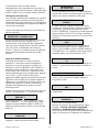
WARNING
IMPORTANT
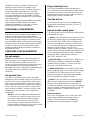
To help prevent drip tray overflow after using the dehumidifier, always purge the unit before moving.
1. Turn the unit off and allow the plugged in dehumidifier to rest for 10 minutes.
2. Press the PURGE key and while the purge pump is operating, tip the unit back approximately 45° and hold the
unit in place until the purge cycle is complete. The manual purge cycle lasts approximately 10 seconds.
3. Return the unit to the upright position and press PURGE one more time to empty the pump.
Remove the dehumidifier promptly from the job site once these steps have been completed.
07-01674J F410, F411 1 Dri-Eaz Products, Inc.

CONTENTS GUIDE
Positioning a dehumidifier .............................. 3
Parts identification ........................................... 2
Operating your dehumidifier .......................... 3
Maintenance ..................................................... 5
Transport and storage ..................................... 6
Cleaning ............................................................ 7
System status messages ................................ 8
Error messages ................................................ 8
Troubleshooting ............................................... 9
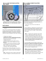
INTRODUCTION
Dri-Eaz dehumidifiers reduce humidity in enclosed
structural environments by removing water vapor from
the air. With proper use, your dehumidifier can help dry
carpet, carpet pad, floors, walls, building contents and
more. Using Dri-Eaz dehumidifiers can also help prevent
secondary damage caused by high humidity. For best
results, use your dehumidifiers with Dri-Eaz TurboDryer
airmovers placed around the perimeter of the room to
distribute heat energy and release moisture from wet
surfaces into the air.
How LGR dehumidifiers work
Dri-Eaz low-grain refrigerant dehumidifiers operate by
pulling moist air in across a very cold evaporator core.
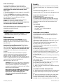
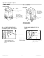
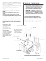
The moisture in the air condenses on the coil. In certain
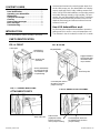
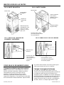
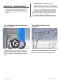
Rugged rotomolded
housing resists dents
and scratches and is
easy to maintain.
FIG. B: REAR
Integrated handle.
Lower back panel. Remove
this panel to access the
pump for servicing.
Drain hose pocket.
Control panel.
Molded pocket
for cord storage.
Humid air inlet
(both sides).
Process (dehumidified)
air outlet. May be used
with standard 12" rigid
or layflat ducting.
FIG. A: FRONT
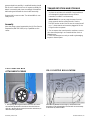
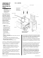
FIG. C: POWER AND PUMP
ATTACHMENT POINTS
Power cord socket.
Lower back panel. Remove the
five retaining screws to remove
pump for cleaning.
FIG. D: PUMP ACCESS PANEL
Bottom of back
polyethylene housing.
Remove two bolts to
remove pump for cleaning.
PARTS IDENTIFICATION
07-01674J F410, F411 2 Dri-Eaz Products, Inc.

conditions, the machine operates in defrost mode,
warming any frost that has accumulated on the
evaporator coil back into water. The water collects in a
tray and is pumped out through a hose. Onboard
sensors continually monitor environmental conditions
and system operations of the dehumidifier, including
temperature and relative humidity, which can be viewed
on the display panel.
LGR (Low Grain Refrigerant) dehumidifiers have better
heat exchange and defrost abilities than regular
refrigerant dehumidifiers, and are able to continue
removing moisture in drier environments.
POSITIONING A DEHUMIDIFIER
For best results, operate your dehumidifiers in an
enclosed area, as this creates a drying chamber. Close
all doors and windows that open to the outside to
maximize the unit’s water removal efficiency. Also, keep
traffic though the drying chamber to a minimum. Place
your dehumidifier against a wall, away from obstructions,
and keep it away from anything that could block airflow
into and out of the unit. For more information about
creating an optimum drying environment, contact Dri-
Eaz at 800-932-3030.
OPERATING YOUR DEHUMIDIFIER
Set unit upright
NOTICE: If you transport an i-Series dehumidifier in a
horizontal position, set it upright and let it stand for at
least 30 minutes before you turn it on. When the
machine is horizontal, the oil from the compressor flows
into the refrigerant coils reducing the ability of the
dehumidifier to function. Letting the unit stand upright for
30 minutes allows the oil to flow back into the
compressor.
Set up drain hose
The i-Series condensate pump connects to a plastic
drainage hose that is located in the pocket on the back
of the unit. This hose is equipped with a quick-connect
fitting for quick attachment to the provided 40-ft. drain
hose. Unwrap the entire hose and place the unattached
end in a sink, drain, bucket or outside – anywhere that
water can drain out safely. If you use a bucket or other
receptacle for water collection, check it regularly to
prevent spills.
NOTE: Uncoil and straighten the entire drain hose.
Do not leave any of part of the hose coiled on the
unit and do not place the end of the hose higher
than 20 ft. (6 m) above the top of the unit. Also
check for kinks, or obstructions that would restrict
the flow of water. Failure to do so may cause a water
backup in the pump resulting in leakage.
Plug in electrical cord
The i-Series dehumidifier should be plugged into a
GFCI-protected 115 volt outlet rated for at least 15
amps.
Remove the cord from its storage pocket and uncoil it.
Always plug the cord firmly into the unit first, and then
plug the other end into a suitable outlet.
Turn the unit on
The control panel on the i-Series dehumidifier has a
display and a touchpad with four keys. Press the
ON/OFF to turn the unit on.
How to use the control panel
The control panel on the LGR 2800i has a display and a
touchpad with four keys.
ON/OFF. Press the ON/OFF key to turn the unit on or
off. When the machine turns on, the display normally
reads PLEASE WAIT COMP. DELAY and performs a
numeral count down from a maximum of 60 seconds
to 0. This delay allows time for refrigerant pressures to
equalize for easier starting. If you don’t see a
compressor delay countdown, a delay is not necessary
and the machine will begin operation immediately. Once
the unit completes the compressor delay, the display
shows UNIT ON XX HRS and cycles between
INLET XX°F and INLET XX%.
DISPLAY MENU. Press the DISPLAY MENU key to
cycle through the display of additional dehumidifier
conditions and User Settings. To return to the main
menu, press the ON/OFF button once.
MENU SELECTION. Press the MENU SELECTION
key to change the values on the "User Defined" settings.
The MENU SELECTON key acts as the UP key for
adjusting the setpoint for Humidistat mode operation.
See User Settings Menu (below) for details.
PURGE. Press the PURGE key to manually empty
water from the condensate pump reservoir. NOTICE:
Always press the purge key prior to moving the unit.
During normal operation, the pump purges automatically
every six minutes, or whenever the reservoir is full. The
display will read PUMP PURGING with a numeral
countdown.
Main menu display
When unit is first plugged in to AC power, the control
panel display will briefly cycle through a series of
displays. This is part of the unit’s self-diagnosis
procedure and no user intervention is required.
07-01674J F410, F411 3 Dri-Eaz Products, Inc.

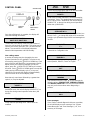
CONTROL PANEL
ON/OFF
DISPLAY
DISPLAY
MENU
MENU
SELECTION /
UP KEY
PURGE PUMP
Once the self-diagnosis is complete, the display will
show the following information:
UNIT ON 00 HRS
INLET 00°F / INLET 00%
The first line of the display shows the total number of
hours the unit has been in operation. This value may be
reset to zero to track job hours (see “Job Hours Reset”
below). The second line of the display alternates
between inlet temperature and inlet humidity.
User settings menu
A number of settings may be changed by the user.
System information is also available. These items are
accessed by pressing the
DISPLAY MENU key. Each
press of the key will display the next parameter (see list
below). When you reach the parameter you wish to
adjust, press the
MENU SELECTON key to increase
the value. Press
DISPLAY MENU again to accept the
setting and re-start the display cycle. If no keys are
selected for 20 seconds the display will automatically
reset and return to the normal display mode.
Note that only menu items followed by a greater-than
symbol ( > ) may be adjusted.
JOB HOURS
RESET? >
Press to reset hours to zero. NOTE: When in
Humidistat mode, the unit will display HUMIDISTAT on
the top line during normal operation rather than JOB
HOURS.
LIFE HOURS
00 HRS
Shows total unit operating hours. Value cannot be
modified.
INLET OUTLET
00° 00% 00° 00%
Shows current temperature and RH of inlet and outlet.
HUMIDISTAT MODE
ON/OFF >
In ON mode, unit will maintain the humidistat setpoint
(see below). Press to toggle between ON and OFF.
NOTE: When in Humidistat mode, the unit will display
HUMIDISTAT on the top line during normal operation
rather than JOB HOURS.
HUMIDISTAT
SETPOINT 00% >
Sets humidity level when unit is in Humidistat Mode (see
above). Press to change RH value at 5% increments.
Settings cycle upward through 90%RH and start again at
30%RH.
TEMP UNITS
F° >
Shows current temperature scale. Press to select
Fahrenheit or Centigrade scale.
LANGUAGE
ENGLISH >
Shows current display panel language. Press to
select Spanish, German, French or English.
COIL TEMP
00°F
Displays the cold (evaporator) coil temperature.
SENSOR ID >
00000000
This function not in use. Press
to cycle through the
following values: SENSOR TYPE, SENSOR REVISION,
and SENSOR CONF REV. A Dri-Eaz service technician
may ask you for these values when diagnosing a
problem.
COMPRSSR CURRENT
0.0 A
Shows compressor current draw in amps.
Error messages
If the i-Series onboard diagnostics discover a problem,
the unit will display an error message. See “System
Status Messages” and “Error Messages,” p. 8, for a
summary of messages.
07-01674J F410, F411 4 Dri-Eaz Products, Inc.

At the end of the job
As with all dehumidifiers, once the drying job is
completed, it is important to make sure the unit is
completely purged of water before moving it. To ensure
that all water has drained into the pump, follow
these steps:
1. Turn the unit off and allow the plugged in dehumidifier
to rest for 10 minutes.
2. Press the PURGE key and while the purge pump is
operating, tip the unit back approximately 45° and hold
the unit in place. The manual purge cycle lasts
approximately 10 seconds.
3. Return the unit to the upright position and press
PURGE one more time to empty the pump.
Remove the dehumidifier promptly from the job site
once these steps have been completed.
Before transporting, be sure to remove the external drain
hose, drain it carefully, and return it to the pocket
provided on the back of the unit.
MAINTENANCE
WARNING! ELECTRIC SHOCK HAZARD. Unplug the
dehumidifier before performing any maintenance.
Before each use
Inspect the electrical cord for damage. Look for
fraying, cuts, etc. Do not use the unit if you find any
damage. Call Dri-Eaz for the nearest Service Center at
800-932-3030.
Inspect and vacuum filter as needed. The i-Series
dehumidifiers are equipped with a 3M™ High Air-Flow
filter. The HAF filter may be vacuumed clean and reused
up to three times. Do not rinse or wash the HAF filter,
as it will reduce the effectiveness of the electrostatic
material.
Keep a clean filter in the unit at all times to protect
internal components from dust and other particulate
build-up. Vacuum or replace filter before each job.
Replace only with a new 3M HAF Filter (Dri-Eaz part no.
F421). For parts and service call your local distributor or
contact the Dri-Eaz Service Department at
800-932-3030 or 360-757-7776.
CAUTION: Dust can cause the unit to overheat and
shut down. Do not operate when excessive dust or
airborne particles are present, such as during
sanding or spray-painting. Inspect and clean air filter
elements and coils frequently.
IMPORTANT: Replace the HAF filter whenever 1)
it has been vacuumed clean 3 times or 2) it has
been used on a mold remediation job or
otherwise exposed to potentially dangerous
contaminants.
Monthly
Check coils. Dirty coils can cause the unit to overheat.
Clean when visibly dirty. See “Instructions for Cleaning,”
p. 7.
Check heat exchange block. Clean out with
compressed air only. Take care not to damage the block.
Inspect and clean the pump. To remove the
condensate pump unit:
SERVICING THE PUMP AND DRAIN PAN
To maintain proper operation, the pump and drain pan
assembly should be periodically removed and cleaned.
Follow these steps to clean the pump and drain pan
assembly:
Tools Needed
Philips screwdriver
Flat blade screwdriver
⅜ in. and
15
∕
16
in. sockets and driver
Cleaning cloths
DISASSEMBLY AND CLEANING
1. Unplug unit, then remove the power cord from the
socket at the base of the unit. Remove pump hose at
quick-connect.
2. Remove HAF filter.
3. Remove the two bolts from the upper front cover.
4. Remove one bolt each from the upper back corner of
side covers A and B (see Fig. A)
5. Remove four bolts from the lower back panel. The
back/top panel may now be removed.
6. Remove lower back metal panel (unscrew the five
attachment screws).
7. Place a firm support under the base of the unit so that
the left wheel may be removed.
8. Using the flat blade screwdriver, carefully pry the
center hub cap loose from the left wheel. Use the
15
∕
16
in.
socket to remove the retaining nut and slide the wheel
off. See Fig E, #1.
9. Remove the two electric box retaining screws (see Fig
E, #2.).
10. Tilt the bottom of the electric box to the right and
slide outward (Fig F). It is not necessary to disconnect
any electrical cables.
11. Remove drain hose from pump assembly and slide
pump and tray assembly out of the unit.
12. Lift pump body out of plastic catch tray.
13. Wipe or rinse off all surfaces of the plastic catch tray
with a damp cloth.
CLEANING THE PUMP AND PUMP TRAY
14. Remove the pump assembly from the pump tray and
set pump aside. Wipe or rinse out pump tray and wipe
dry.
15. Remove pumpout hose from the check valve outlet.
16. Unscrew check valve. Using needle nose pliers
carefully remove bottom of check valve assembly by
inserting one side of pliers approximately ⅛ in. into hole,
07-01674J F410, F411 5 Dri-Eaz Products, Inc.

grasp and pull out carefully. A small ball bearing should
fall out so be careful not to lose it. Inspect assembly for
debris in assembly and clean accordingly. Reinstall the
ball bearing and reinstall the check valve assembly.
Reassemble in reverse order. The dehumidifier is now
ready for use.
Annually
Have the pump system inspected by the Dri-Eaz Service
Department (800-932-3030) or by a qualified service
center.
TRANSPORTATION AND STORAGE
NOTICE: Handle the unit carefully. Do not drop, throw,
or place the unit where it could fall. Rough treatment
can damage this equipment and may create a
hazardous condition or void warranty.
IMPORTANT: Be sure to purge the water from the
pump reservoir before moving the unit. See the
PURGE function under "How to use the control panel"
on p. 3. Note that the unit must be plugged in for the
Purge function to operate.
1. Do not expose the control panel to moisture, snow or
rain when transporting in uncovered vehicles such as
flatbed trucks.
2. Store and transport securely to avoid any damaging
impact to internal parts.
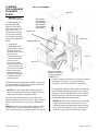
FIG. F: ELECTRIC BOX LOCATION
After removing attachment screws (Fig. E), tilt the bottom of the
electrical box to the right and slide it out. Set aside. It is not necessary
to disconnect any electrical cables.
FIG. E: ELECTRIC BOX
ATTACHMENT SCREWS
1. After placing a firm support under the base of the unit, remove
the center hub cap and remove the axle nut. The wheel will now
slide off. 2. Remove the two screws (shown in the circles above) to
detach the electric junction box.
07-01674J F410, F411 6 Dri-Eaz Products, Inc.

CLEANING
COILS AND HEAT
EXCHANGE
BLOCK
Warning! Unplug
unit before servicing.
To help keep the unit
operating efficiently,
keep the coils and the
air-to-air heat exchange
block clean. These
components are easily
accessed by removing
the side and rear covers
of the unit as described
below:
1. Unplug unit.
2. Unplug the power
cord from the socket at
the base of the unit.
Remove pump hose at
quick-connect.
3. Remove HAF filter.
4. Remove both side
covers A and B
(unscrew two bolts
shown for each panel).
5. Remove back cover
(unscrew the four bolts
shown on the back
and the two bolts on
the upper front panel).
6. Remove the heat
exchange block.
Inspect the heat exchange block carefully. If necessary,
use compressed air to clear the channels of the block,
taking care not to damage the block.
NOTICE: The unit is fitted with sensitive electronic
sensors. Protect the sensors from impact and do not
expose them to water or cleaning solution.
Vacuum or use compressed air on both sides of the
upright (condenser) coil until it is clean. Take care not to
let the nozzle touch the fins; as this may damage the
fins.
NOTICE: Dri-Eaz Coil Cleaner (Dri-Eaz part no. S402)
may be used on the horizontal cold (evaporator) coil
only. Follow instructions on product label. Take care not
to spray or wipe Coil Cleaner on or near any electrical
components or sensors. To clean the vertical
(condenser) coil, contact Service for instructions.
To reassemble, follow the above steps in reverse. Be
sure to reinstall heat exchange block in the original
orientation. When installing the rear cover, carefully
thread the pump hose through the hole in the back
pocket before putting the cover in place.
NOTICE: Rubber strips are attached to the outside
edges of the evaporator and condenser coils to
provide an airtight seal around the heat exchange
block. When reinstalling the block, make sure the
seals are in place and are not kinked or folded.
Rear cover
Side cover A
Side cover B
HAF filter
FIG. G: CLEANING
Pump hose – thread up
through hole in bottom of
rear hose pocket before
reinstalling cover.
Condenser coil
Evaporator (cold) coil
Air-to-air heat
exchange block.
Arrows printed on
the block indicate
correct orientation
for installation.
07-01674J F410, F411 7 Dri-Eaz Products, Inc.

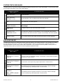
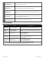
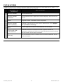
SYSTEM STATUS MESSAGES
The table below is a summary of status and data messages produced by the i-Series dehumidifers. The left column shows
the messages that appear on the control panel display.
CONTROL PANEL
MESSAGE
EXPLANATION
SYSTEM STATUS
UNIT ON 00 HRS Normal operation.
UNIT ON 00 HRS
DEFROST CYCLE
Normal operation. Unit is in defrost mode. No action required.
OFF Unit is turned off. AC power present.
UNIT ON 00 HRS
POWER FAILURE>
Unit experienced a power failure but has successfully restarted. Press > to clear
this message.
HUMIDISTAT
INLET XXX°F
Humidistat mode is active and dehumidifier energized.
HI TEMP CYCLE
REMAINING 00 MIN
LGR 2800i only. Indicates normal operation. Unit has detected higher ambient
temperatures and switched modes to operate more efficiently. No action required.
[display is blank] No AC power. Wireless transmitter functioning normally. No action required.
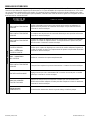
ERROR MESSAGES
The table below shows error messages that the system may display. If the display shows an “ER” message, first unplug
the unit and then plug it back in. This may re-set the electronics, and if so, no further action is required. If the error
message reappears, try the solution shown under “Explanation.” If this still does not fix the problem, contact your local
authorized service center or the Dri-Eaz Service Department at 800-932-3030.
CONTROL PANEL
MESSAGE
EXPLANATION
SYSTEM ERROR
ER1 CONTACT SERVICE
CENTER
Check AC power for inadequate voltage. The electronic control panel may require
replacement. Contact service.
ER2 CONTACT SERVICE
CENTER
The electronic control panel may require replacement. Contact service.
ER3 CONTACT SERVICE
CENTER
Check defrost sensor for proper connection. Check sensor cable for damage.
Sensor assembly may need replacement. Contact service.
ER4 √ DEFROST SENSOR
CONNECT
– or –
ER4 √ OUTLET SENSOR
CONNECT
Check defrost sensor for proper connection. Check sensor cable for damage.
Sensor assembly may need replacement. Contact service.
07-01674J F410, F411 8 Dri-Eaz Products, Inc.

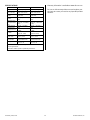
ER5 √ SENSOR
CONNECTION ON BD
Check temp/RH sensor connections.
ER6 CONTACT
SERVICE CENTER
The high voltage board may need replacing. Contact service.
ER7 INVALID
MODEL SETTING
Incorrect DIP switch settings or firmware version for that specific model. Contact
service.
ER8 BUTTON STUCK √
ALL BUTTONS
Press each membrane button and check for proper operation. Membrane overlay
may require replacement. Contact service.
ER9 PUMP BLOCKED √
CHECK PUMP & HOSE
Check for obstructions in drain hose. Check the pump.
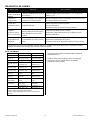
TROUBLESHOOTING
FAULT CAUSE SOLUTION
Water drips out
when moving
unit
Unit was unplugged before
purging was complete.
Purge unit before moving. See “At the End of the Job,” p. 5.
Unit does not
operate
No power to machine.
Unit not switched on.
Plug in unit; check power at outlet and at base of unit. Switch
unit on.
Blower wheel
not turning
Obstructed blower.
Remove duct ring and grill.
Remove obstruction.
Replace duct ring and grill.
Unit operating,
but room not dry
Not enough time to dry.
Poor air movement in room.
Excessive moist air infiltration.
Allow more time for drying.
Increase air movement with air movers.
Reduce infiltration.
Unit collects too
little water
Room air is dry.
Room temperature is too low.
Check humidity with hygrometer.
Increase room temperature.
Check filter and coils; clean as necessary.
If the problem you are experiencing is not listed here, call your local distributor or contact
our Service Department toll-free at 800-932-3030 for further assistance.
07-01674J F410, F411 9 Dri-Eaz Products, Inc.

SPECIFICATIONS
Model LGR 2800i F410 LGR 3500i F411
Weight 165 lbs. | 75 kg 165 lbs. | 75 kg
Dimensions
(H × D × W)
40.5 × 23 × 24 in.
103 × 58 × 61 cm
40.5 × 23 × 24 in.
103 × 58 × 61 cm
Power
8.0 amps,
120 volts
11.2 amps,
120 volts
Water removal
AHAM
(80°F/60% RH)
130 pts. | 61.5 liters /
day
170 pts. | 80.4 liters /
day
Water removal
max. (90°F/90%
RH)
200 pts. | 94.6 liters /
day
240 pts. | 113.6 liters
/ day
Water removal
80°F/20% RH
20 pts. | 9.5 liters /
day
22 pts. | 10.4 liters /
day
Max process air
400 CFM | 679.7
CMH*
400 CFM | 679.7
CMH*
Air filter
3M HAF filter
(part no. F421)
3M HAF filter
(part no. F421)
Power cord
Detachable
25 ft. | 7.6 m
Detachable
25 ft. | 7.6 m
Construction Rotomolded shell Rotomolded shell
Safety
ETL certified to CSA
22.2 no. 92
ETL certified to CSA
22.2 no. 92
Specifications are subject to change without notice. Some values
may be approximate.
*Automatic variable speed for optimized performance.
Warranty information is available at www.dri-eaz.com.
Be sure to visit warranty.drieaz.com and register your
purchase to ensure you receive any important product
releases.
07-01674J F410, F411 10 Dri-Eaz Products, Inc.

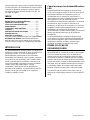
Manual para el usuario
Deshumidificador Portátil LGR 2800i (F410)
Deshumidificador Portátil LGR 3500i (F411)
DRI-EAZ PRODUCTS, INC.
15180 Josh Wilson Road, Burlington, WA 98233
Teléfono: 800-932-3030 Fax: 360-757-7950 www.dri-eaz.com
La serie de deshumidificadores Dri-Eaz
®
LGR iSeries reduce la humedad en ambientes
cerrados eliminando el vapor de agua que se encuentra en el aire. El modelo iSeries está
creado de modo que sea resistente, duradero y fácil de transportar, características que lo
convierten en un elemento sumamente adecuado para la reparación de daños causados por
el agua, el secado de estructuras, la construcción y otros usos para los que se necesita
temporalmente un deshumidificador de alto rendimiento.
Patents: http://www.LBpatents.com
LEA Y GUARDE ESTAS INSTRUCCIONES
INSTRUCCIONES DE SEGURIDAD
¡ADVERTENCIA! No altere ni modifique su producto
de ninguna manera. Utilice únicamente repuestos
autorizados por Dri-Eaz Products, Inc. El uso o
modificación de repuestos no aprobados podría
ocasionar algún peligro y anulará su garantía. Para
solicitar asistencia, comuníquese con su
distribuidor autorizado de Dri-Eaz.
¡ADVERTENCIA! Peligro de sufrir una descarga
eléctrica, lastimarse con el ventilador rotatorio,
quemarse con una superficie caliente. Desenchufe la
unidad antes de abrir la tapa para limpiarla o
repararla. La unidad debe tener descarga a tierra.
• Controle el cable de alimentación antes de usar. Si
está dañado, no lo use. Para desenchufar el
aparato, tire siempre del enchufe (nunca del cable).
• Coloque el enchufe de tres clavijas que está en el
extremo del cable de alimentación en un
tomacorriente con descarga a tierra adecuado. No
use adaptadores. Nunca corte la tercera clavija. No
use cables prolongadores.
• La unidad debe utilizarse en un circuito eléctrico de
115 V/60 Hz, protegido por un interruptor del circuito
de fallos de conexión a tierra (GFCI, por sus siglas
en inglés).
• Mantenga el motor y los cables secos.
• No intente reparar la unidad. Para conocer los
Centros de Servicio Técnico Autorizados, llame a
Dri-Eaz al 800-932-3030.
ANTES DE COMENZAR
Cómo desembalar la unidad
Conserve todo el material de embalaje y las cajas por si
tiene que devolver el equipo. Busque y reserve las pilas
AA, ya que debe colocarlas antes de usar la unidad.
Registro de la garantía
Visite warranty.drieaz.com para registrar su compra. El
registro nos permite brindarle mejor asistencia en el uso,
el mantenimiento o la reparación de su equipo, y
también comunicarnos con usted en caso de que
tengamos información de seguridad importante sobre su
producto de Dri-Eaz.
Si considera que su producto
ADVERTENCIA
IMPORTANTE
Para evitar que la bandeja de goteo se desborde después de usar el deshumidificador, recuerde purgar
siempre la unidad antes de moverla.
1. Apague la unidad durante 10 minutos para que descanse, pero no la desenchufe.
2. Presione el botón PURGAR y, mientras la bomba esté funcionando, incline la unidad hacia atrás
aproximadamente 45º y manténgala en esa posición; el ciclo de purgado manual dura unos 10 segundos.
3. Enderece la unidad y vuelva a presionar PURGAR para eliminar el agua que haya quedado en el interior.
Una vez que haya terminado este proceso, retire el deshumidificador inmediatamente del lugar de trabajo
07-01674J F410, F411 11 Dri-Eaz Products, Inc.

necesita reparación, tenga a mano el modelo del equipo,
el número de serie y el comprobante de compra original,
y llame a su distribuidor para que lo ayude a obtener
una autorización para devolver el producto (RMA, por
sus siglas en inglés).
ÍNDICE
Dónde colocar un deshumidificador ............... 12
Identificación de las partes .............................. 13
Cómo usar su deshumidificador ..................... 13
Mantenimiento ................................................... 15
Transporte y almacenamiento ......................... 17
Limpieza ............................................................. 17
Mensajes del estado del sistema..................... 19
Mensajes de error ............................................. 19
Detección de problemas ................................... 20
Consulte “Sensor a distancia HygroTrac” (página Error!
Bookmark not defined.) para obtener información
general sobre cómo usar la unidad con el Sistema de
Control a Distancia HygroTrac (adquirido por separado).
INTRODUCCIÓN
Los deshumidificadores Dri-Eaz reducen la humedad en
ambientes cerrados eliminando el vapor de agua que se
encuentra en el aire. Si se usa correctamente, el
deshumidificador puede ayudar a secar alfombras,
almohadillas para alfombras, pisos, paredes, elementos
en el interior de una propiedad y más. También puede
ayudar a prevenir daños secundarios causados por el
exceso de humedad. Para obtener mejores resultados,
cuando use los deshumidificadores, coloque
ventiladores TurboDryer de Dri-Eaz alrededor del
perímetro de la habitación, a fin de distribuir la energía
térmica y hacer que la humedad de las superficies
mojadas se pierda en el aire.
Cómo funcionan los deshumidificadores
LGR
Los deshumidificadores refrigerantes de grano bajo
(LGR, por sus siglas en inglés) de Dri-Eaz hacen que el
aire húmedo atraviese un evaporador muy frío. La
humedad del aire se condensa en el serpentín. En
determinados momentos, la máquina funciona en modo
"descongelación", ya que calienta la escarcha
acumulada en el serpentín del evaporador y la convierte
nuevamente en agua. El agua se acumula en un
recipiente y se elimina por una manguera. Los sensores
integrados controlan permanentemente las condiciones
ambientales y las operaciones del sistema del
deshumidificador, incluidas la temperatura y la humedad
relativa, que pueden observarse en la pantalla de
visualización.
Los deshumidificadores refrigerantes de grano bajo
(LGR) poseen una mayor capacidad de intercambio de
calor y de descongelación que los deshumidificadores
refrigerantes normales; asimismo, pueden seguir
eliminando humedad en ambientes más secos.
DÓNDE COLOCAR UN
DESHUMIDIFICADOR
Para obtener mejores resultados, utilice su
deshumidificador en un espacio cerrado, lo que permite
crear una cámara de secado. A fin de aumentar al
máximo la eficacia de la unidad para eliminar el agua,
cierre todas las puertas y ventanas que den al exterior.
Además, trate de que el tránsito dentro de la cámara de
secado sea mínimo. Coloque su deshumidificador contra
una pared, lejos de cualquier elemento que lo obstruya,
y manténgalo alejado de cualquier objeto que pueda
bloquear el flujo de aire que entra y sale de la unidad.
Para obtener más información sobre cómo crear un
ambiente de secado óptimo, llame a Dri-Eaz al 800-932-
3030.
07-01674J F410, F411 12 Dri-Eaz Products, Inc.

IDENTIFICACIÓN DE LAS PARTES
CÓMO USAR SU DESHUMIDIFICADOR
Coloque la unidad en posición vertical
AVISO: Si transporta un deshumidificador i-Series en
posición horizontal, enderécelo y déjelo en posición
vertical durante al menos 30 minutos antes de
prenderlo. Cuando la máquina está en posición
horizontal, el aceite del compresor fluye hacia los
serpentines refrigerantes, lo que disminuye la capacidad
de funcionamiento del deshumidificador. Dejar la unidad
en posición vertical durante 30 minutos permite que el
aceite vaya nuevamente hacia el compresor.
Coloque la manguera de drenaje
La bomba de condensado del modelo i-Series se
conecta a una manguera de drenaje plástica, ubicada en
la cavidad de la parte de atrás de la unidad. Dicha
manguera incluye un adaptador de conexión rápida para
ajustarla fácilmente a la manguera de drenaje de 40 pies
(12 m) proporcionada.
Desenrolle toda la manguera y
coloque el extremo suelto en una pila, un desaguadero,
un balde o afuera: en cualquier lugar donde el agua
Panel de control.
Cavidad moldeada
para guardar el
cable.
Entrada de aire
húmedo (ambos
lados).
Salida de aire procesado
(deshumidificado). Puede
usarse con un conducto
estándar de 12" (30.5 cm)
rígido o plano.
FIG. A: PARTE DELANTERA
Armazón rotomoldeado
fuerte, resistente a
abolladuras y rayones, y
fácil de mantener.
FIG. B: PARTE TRASERA
Manija integrada.
Panel trasero inferior. Quítelo
para acceder a la bomba y realizar
tareas de mantenimiento.
Cavidad para guardar la
manguera de drenaje.
FIG. C: PUNTOS DE CONEXIÓN DE
LA BOMBA Y LA ENERGÍA
Panel trasero inferior. Quite los
cinco tornillos que lo sostienen para
sacar la bomba y limpiarla.
FIG. D: PANEL DE ACCESO A LA BOMBA
Parte inferior del armazón
trasero de polietileno.
Quite los dos pernos para
sacar la bomba y
limpiarla.
Entrada del cable de
alimentación.
07-01674J F410, F411 13 Dri-Eaz Products, Inc.

PANEL DE CONTROL
PRENDIDO/APAGADO
PANTALLA
MOSTRAR MENÚ
SELECCIÓN DEL
MENÚ/ARRIBA
PURGAR BOMBA
pueda drenar de forma segura. Si acumula el agua en
un balde u otro recipiente, contrólelo con frecuencia
para evitar derrames.
NOTA: Desenrosque y estire toda la manguera de
drenaje. No deje ninguna parte de la manguera
enroscada en la unidad ni coloque el extremo de la
manguera a más de 20 pies (6 m) por encima de la
parte superior de la unidad. Controle también que
no haya dobleces u obstrucciones que impidan el
paso del agua. De lo contrario, es posible que la
bomba se tape y pierda agua.
Enchufe el cable eléctrico
El deshumidificador i-Series debe enchufarse en un
tomacorriente de 115 voltios, protegido por un GFCI,
con capacidad para 15 amperios como mínimo. Saque
el cable de la cavidad donde está guardado y
desenrósquelo. Conecte siempre primero y con firmeza
el cable que va a la unidad. Después, enchufe el otro
extremo del cable en un tomacorriente adecuado.
Prenda la unidad
El panel de control del deshumidificador i-Series tiene
una pantalla y una placa sensible al tacto con cuatro
teclas. Presione la tecla
PRENDIDO/APAGADO
para prender la unidad.
Cómo usar el panel de control
El panel de control del LGR 2800i tiene una pantalla y
una placa sensible al tacto con cuatro teclas.
PRENDIDO/APAGADO. Presione la tecla
PRENDIDO/APAGADO para prender o apagar la
unidad. Cuando se prende la máquina, suele aparecer
en la pantalla la leyenda POR FAVOR ESPERE RETAR
COMPRS y se produce una cuenta regresiva que va
desde un máximo de 60 segundos hasta 0. Esta demora
permite que las presiones de refrigerado se equilibren
para que el comienzo sea más sencillo. Si no aparece
una cuenta regresiva por el retardo del compresor,
significa que dicho retardo no es necesario y que la
máquina comenzará a funcionar de inmediato. Una vez
que finaliza el retardo del compresor, aparece en la
pantalla PRENDIDO XXXX H, y se alterna el mensaje
ENTRADA XXX °F con el mensaje ENTRADA XX%.
MOSTRAR MENÚ. Presione la tecla MOSTRAR
MENÚ para ver en la pantalla otros estados del
deshumidificador y las Configuraciones del Usuario.
Para volver al menú principal, presione la tecla
PRENDIDO/APAGADO una sola vez.
SELECCIÓN DEL MENÚ. Presione la tecla
SELECCIÓN DEL MENÚ para cambiar los valores en
las Configuraciones del Usuario. La tecla SELECCIÓN
DEL MENÚ también funciona como la tecla ARRIBA, a
fin de modificar el valor prefijado para que la unidad
funcione en modo “humidistato”. Para obtener una
descripción detallada, consulte “Menú de
configuraciones del usuario” (más abajo).
PURGAR. Presione el botón PURGAR para vaciar en
forma manual el agua que se encuentra en el depósito
de la bomba de condensado. AVISO: Presione siempre
la tecla de purgado antes de mover la unidad. Durante el
funcionamiento normal, la bomba se purga
automáticamente cada seis minutos, o cada vez que el
depósito esté lleno. En la pantalla se verá BOMBA
PURGANDO y una cuenta regresiva.
Pantalla del menú principal
Cuando la unidad se enchufa por primera vez a la
corriente alterna, la pantalla del panel de control
mostrará rápidamente una serie de datos. Este
procedimiento forma parte del autodiagnóstico de la
unidad y no se necesita la intervención del usuario.
Cuando finaliza el autodiagnóstico, la pantalla exhibirá la
siguiente información:
PRENDIDO XXXX H
ENTRADA XXX °F / ENTRADA XX%
La primera línea de la pantalla indica la cantidad total de
horas que ha funcionado la unidad. Este valor puede
llevarse a cero para hacer un seguimiento de las horas
de trabajo (vea más abajo "Reinicio de las horas de
trabajo"). La segunda línea de la pantalla alterna la
temperatura de entrada con la humedad de entrada.
Menú de configuraciones del usuario
El usuario puede cambiar varias configuraciones.
También tiene disponible información del sistema. Se
accede a estas opciones presionando la tecla
MOSTRAR MENÚ. Cada vez que presione la tecla, verá
en la pantalla el parámetro siguiente (vea la lista más
abajo). Cuando llegue al parámetro que quiere
modificar, presione la tecla
SELECCIÓN DEL MENÚ
para aumentar el valor. Vuelva a presionar
MOSTRAR MENÚ para aceptar el cambio y reiniciar el
ciclo que muestra la pantalla. Si en el término de 20
segundos no presiona ninguna tecla, la pantalla se
reiniciará automáticamente y volverá al modo normal.
07-01674J F410, F411 14 Dri-Eaz Products, Inc.

Tenga en cuenta que pueden ajustarse solamente los
elementos del menú seguidos por el símbolo de mayor
que (>).
HORAS DE TRABAJO
REINICIAR? >
Presione para llevar las horas a cero. NOTA: Cuando
esté en modo “humidistato”, en lugar de HORAS DE
TRABAJO la línea superior mostrará la palabra
HUMIDISTATO durante el funcionamiento normal.
TOTAL DE HORAS
XXXXXX H
Muestra la totalidad de horas de funcionamiento de la
unidad. El valor no puede modificarse.
ENTRADA SALIDA
XXX° XX% XXX° XX%
Muestra la temperatura y la humedad relativa de entrada
y salida que hay en el momento.
MODO HUMIDISTATO
APAGADO >
En modo “PRENDIDO”, la unidad mantendrá el valor
prefijado del humidistato (vea más abajo). Presione la
tecla para cambiar de PRENDIDO a APAGADO.
NOTA: Cuando esté en modo “humidistato”, en lugar de
HORAS DE TRABAJO la línea superior mostrará la
palabra HUMIDISTATO durante el funcionamiento
normal.
VALOR PREFIJADO
HUMIDISTATO XX%>
Establece el nivel de humedad cuando la unidad está en
modo "humidistato" (vea arriba). Presione la tecla
para aumentar de a 5% el valor de la humedad relativa.
Los valores aumentan hasta llegar al 90% de humedad
relativa y vuelven a comenzar desde el 30%.
TEMPERATURA
C° >
Muestra la escala de temperatura actual. Presione la
tecla para seleccionar grados Fahrenheit o
centígrados.
IDIOMA
ESPANOL >
Muestra el idioma actual de la pantalla. Presione la tecla
para elegir español, alemán, francés o inglés.
TEMP SERPENT
XX °F
Muestra la temperatura del serpentín (evaporador) frío.
SENSOR ID >
XXXXXXXXX
Esta función no está en uso .
Presione la tecla para pasar por los siguientes
valores: TIPO SENSOR, REV SENSOR y REV CONFIG
SENSOR. Es posible que el personal de servicio técnico
de Dri-Eaz le pida estos datos cuando esté evaluando
un problema.
CORR COMPRS
XXXXX A
Muestra la corriente del compresor en amperios.
Mensajes de error
Si el sistema de diagnóstico integrado al modelo i-Series
detecta un problema, la unidad mostrará un mensaje de
error. En “Mensajes estado del sistema” y “Mensajes de
error” (página 19), encontrará un resumen de los
mensajes de estado y los de error.
Al finalizar el trabajo
Como con todos los deshumidificadores, una vez
finalizado el proceso de secado, es importante
asegurarse de que la unidad no contenga agua antes de
moverla. Para asegurarse de que toda el agua haya
drenado hacia la bomba, siga estos pasos:
1. Apague la unidad durante 10 minutos para que
descanse, pero no la desenchufe.
2. Presione el botón PURGAR y, mientras la bomba
esté funcionando, incline la unidad hacia atrás
aproximadamente 45º y manténgala en esa posición; el
ciclo de purgado manual dura unos 10 segundos.
3. Enderece la unidad y vuelva a presionar PURGAR
para eliminar el agua que haya quedado en el interior.
Una vez que haya terminado este proceso, retire el
deshumidificador inmediatamente del lugar de trabajo.
Antes de transportarla, asegúrese de quitar la manguera
de drenaje externa, vaciarla con cuidado y volver a
colocarla en la cavidad que está en la parte de atrás de
la unidad.
MANTENIMIENTO
¡ADVERTENCIA! PELIGRO DE DESCARGA
ELÉCTRICA. Desenchufe el deshumidificador antes
de realizar cualquier tarea de mantenimiento.
07-01674J F410, F411 15 Dri-Eaz Products, Inc.

Antes de cada uso
Controle el cable eléctrico para detectar daños.
Fíjese que el cable no esté pelado, cortado, etc. No use
la unidad si detecta algún daño. Para conocer el Centro
de Servicio Técnico más cercano, llame a Dri-Eaz al
800-932-3030.
Controle y aspire el filtro cuando sea necesario. Los
deshumidificadores i-Series están equipados con un
filtro para alto flujo de aire High Air-Flow (HAF) de 3M™.
El filtro para HAF se puede limpiar con aspiradora y
volver a usar hasta tres veces. No enjuague ni lave el
filtro para HAF, ya que reducirá la eficacia del material
electrostático.
Tenga siempre un filtro limpio en la unidad para proteger
los componentes internos contra la acumulación de
polvo y otras partículas. Aspire o cambie el filtro antes
de cada trabajo. Reemplácelo únicamente con un filtro
para HAF de 3M nuevo (pieza n.º F421 de Dri-Eaz).
Para solicitar piezas y servicio técnico, llame al
distribuidor de su zona o al Departamento de Servicio
Técnico de Dri-Eaz, al 800-932-3030 ó 360-757-7776.
ADVERTENCIA: El polvo puede hacer que la
unidad se recaliente y se apague. No utilice el
equipo cuando haya exceso de polvo o partículas en
el aire, por ejemplo durante el lijado o la pintura con
pulverizador. Controle y limpie los serpentines y los
componentes del filtro de aire con frecuencia.
IMPORTANTE: Reemplace el filtro para HAF
cuando 1) lo haya limpiado con la aspiradora
tres veces o 2) haya sido utilizado en tareas de
eliminación de moho o haya sido expuesto a
sustancias contaminantes potencialmente
peligrosas.
Una vez al mes
Controle los serpentines. Los serpentines sucios
pueden hacer que la unidad se recaliente. Límpielos
cuando los note sucios. Consulte las instrucciones de
limpieza en la página 18.
Controle el bloque de intercambio de calor. Límpielo
con aire comprimido únicamente. Tenga cuidado de no
dañar el bloque.
Controle y limpie la bomba. Para quitar la bomba de
condensado, haga lo siguiente:
MANTENIMIENTO DE LA BOMBA Y LA BANDEJA DE
DRENAJE
A fin de que la unidad siga funcionando correctamente,
debe retirar y limpiar la bomba y la bandeja de drenaje
periódicamente; para hacerlo, siga estos pasos:
Herramientas necesarias
Destornillador Phillips
Destornillador de punta plana
Tubos de ⅜ y
15
∕
16
pulgadas (9.5 y 24 mm) y llave de
tubos
Trapos
DESARMADO Y LIMPIEZA
1. Desenchufe la unidad y luego retire el cable de
alimentación de la entrada que está en la base de la
unidad. Saque la manguera de la bomba de la conexión
rápida.
2. Quite el filtro para HAF.
3. Quite los dos pernos de la tapa superior del frente.
4. Quite el perno de cada esquina trasera superior de
las tapas laterales A y B (vea la Figura A).
5. Quite los cuatro pernos del panel trasero inferior;
ahora puede retirar el panel trasero/superior.
6. Retire el panel metálico trasero inferior (desenrosque
los cinco tornillos restantes).
7. Coloque un soporte firme debajo de la base de la
unidad para sacar la rueda izquierda.
8.
Con el destornillador de punta planta, afloje
cuidadosamente el tapacubos central de la rueda
izquierda. Use el tubo de
15
∕
16
pulgadas para sacar la
tuerca de retención y deslizar la rueda hacia afuera. Vea
la Figura E, #1.
9. Quite los dos tornillos de retención de la caja eléctrica
(vea la Figura E, #2).
10. Incline la parte de abajo de la caja eléctrica hacia la
derecha y deslícela hacia afuera (Figura F). No es
necesario que desconecte ningún cable eléctrico.
11. Saque la manguera de drenaje de la bomba y
deslice la bomba y la bandeja hacia fuera de la unidad.
12. Levante la estructura de la bomba para sacarla de la
bandeja plástica de recolección y aparte la bomba.
LIMPIEZA DE LA BOMBA Y LA BANDEJA DE LA
BOMBA
13. Enjuague o limpie con un trapo húmedo todas las
superficies de la bandeja plástica de recolección.
14. Limpie con un trapo húmedo todas las superficies de
la bomba.
15. Saque la manguera de bombeo de la salida de la
válvula de retención.
16. Desenrosque la válvula de retención. Con una pinza
de punta de aguja, quite cuidadosamente la parte de
abajo de la válvula de retención; para hacerlo,
introduzca un lado de la pinza en el agujero a unas ⅛
pulgadas (3 mm), apriete y retire con cuidado. Es
probable que salga un soporte de bolas; tenga cuidado
de no perderlo. Inspeccione la unidad y límpiela
conforme sea necesario. Vuelva a colocar el soporte de
bolas y la válvula de retención.
Vuelva a armar la unidad siguiendo los pasos anteriores
a la inversa. El deshumidificador está listo para usar.
Una vez al año
Llame al Departamento de Servicio Técnico de Dri-Eaz
(800-932-3030) o a un centro de servicio técnico
habilitado para que controle el sistema de la bomba.
07-01674J F410, F411 16 Dri-Eaz Products, Inc.

TRANSPORTE Y ALMACENAMIENTO
AVISO: Manipule la unidad con cuidado. No la tire
ni la apoye en lugares donde pueda caerse. Si no
trata este equipo con cuidado, puede dañarse y
ocasionar algún peligro, o la garantía puede quedar
anulada.
IMPORTANTE: Antes de mover la unidad,
asegúrese de purgar el agua que se encuentra en el
depósito de la bomba. Consulte “Cómo usar el panel
de control” en la página 14 para obtener información
sobre la función PURGAR. Tenga en cuenta que,
para que purgue, la unidad debe estar enchufada.
1. No exponga el panel de control a humedad, nieve o
lluvia cuando lo transporte en vehículos descubiertos,
tales como los camiones de plataforma.
2. Transpórtelo y almacénelo de manera segura para
evitar cualquier impacto que dañe las partes internas.
FIG. F: UBICACIÓN DE LA CAJA
ELÉCTRICA
Después de quitar los tornillos de fijación (Fig. E), incline la parte de
abajo de la caja eléctrica hacia la derecha y deslícela hacia afuera.
Apártela. No es necesario que desconecte ningún cable eléctrico.
FIG. E: TORNILLOS DE FIJACIÓN DE LA
CAJA ELÉCTRICA
1. Después de colocar un soporte firme debajo de la base de la
unidad, retire el tapacubos central y la tuerca del eje. La rueda se
deslizará hacia afuera.
2. Quite los dos tornillos (marcados con un
círculo en la figura superior) para desmontar la caja de conexiones
eléctricas.
07-01674J F410, F411 17 Dri-Eaz Products, Inc.

LIMPIEZA DE LOS
SERPENTINES Y
DEL BLOQUE DE
INTERCAMBIO DE
CALOR
¡Advertencia!
Desenchufe la unidad
antes de realizar
cualquier tarea de
mantenimiento.
Para contribuir a que la
unidad siga funcionando
eficazmente, mantenga
limpios los serpentines y
el bloque de intercambio
de calor de aire a aire. Se
puede acceder fácilmente
a estos componentes
quitando las tapas
laterales y trasera de la
unidad, tal como se
describe a continuación:
1. Desenchufe la
unidad.
2. Desconecte el cable
de alimentación de la
entrada que está en la
base de la unidad.
Saque la manguera de
la bomba de la
conexión rápida.
3. Quite el filtro para
HAF.
4. Saque las dos tapas
laterales A y B (desatornille los dos pernos que hay en
cada panel).
5. Saque la tapa trasera (desatornille los cuatro
pernos que hay en la parte de atrás y los dos pernos
del panel superior del frente).
6. Quite el bloque de intercambio de calor.
Controle con cuidado el bloque de intercambio de calor.
De ser necesario, use aire comprimido para limpiar las
canaletas del bloque, con cuidado para no dañarlo.
AVISO: La unidad está equipada con sensores
electrónicos sensibles. Proteja los sensores contra
impactos y no los exponga a agua ni a ninguna
solución de limpieza.
Use la aspiradora o el aire comprimido en ambos lados
del serpentín (condensador) vertical hasta que esté
limpio. No permita que la boquilla toque las aletas, ya
que podría dañarlas.
AVISO: El limpiador de serpentín Dri-Eaz Coil Cleaner
(pieza n.º S402 de Dri-Eaz) puede utilizarse únicamente
para el serpentín (evaporador) frío horizontal. Respete
las instrucciones que figuran en la etiqueta del producto.
Tenga cuidado de no rociar o pasar un trapo con Coil
Cleaner en los componentes eléctricos ni en los
sensores, ni cerca de ellos. Para obtener instrucciones
sobre cómo limpiar el serpentín (condensador) vertical,
comuníquese con el Departamento de Servicio Técnico.
Para volver a armar siga los pasos anteriores, pero a la
inversa. Asegúrese de volver a instalar el bloque de
intercambio de calor según la orientación que tenía
originalmente. Antes de volver a colocar la tapa trasera,
pase con cuidado la manguera de la bomba por el
agujero que hay en la cavidad de la parte de atrás.
AVISO: Los bordes exteriores de los serpentines
evaporadores y condensadores tienen burletes de
goma que crean un cierre hermético alrededor del
bloque de intercambio de calor. Cuando vuelva a
instalar el bloque, asegúrese de que los burletes estén
en el lugar correspondiente y no estén torcidos ni
doblados.
Tapa trasera.
Tapa lateral A.
Tapa lateral B.
Filtro de aire para HAF.
FIG. G: LIMPIEZA
Antes de volver a colocar la tapa, pase la
manguera de la bomba por el agujero
que hay en la parte de abajo de la
cavidad trasera para la manguera.
Serpentín condensador.
Serpentín (frío) evaporador.
Bloque de intercambio de
calor de aire a aire. Las
flechas impresas en el
bloque indican el sentido
correcto de la instalación.
07-01674J F410, F411 18 Dri-Eaz Products, Inc.

MENSAJES DEL ESTADO DEL SISTEMA
El siguiente cuadro es un resumen de los mensajes de datos y estado que generan los deshumidificadores i-Series. La
columna de la izquierda muestra los mensajes que aparecen en la pantalla del panel de control.
MENSAJE DEL PANEL
DE CONTROL
EXPLICACIÓN
ESTADO DEL SISTEMA
PRENDIDO XXXX H Funcionamiento normal.
PRENDIDO XXXX H
CICLO DESCONGEL
Funcionamiento normal. La unidad está en modo “descongelación”. No hay
que hacer nada.
APAGADO La unidad está apagada. Hay corriente alterna.
PRENDIDO XXXX H
FALLA ELECTRICA>
La unidad experimentó una falla eléctrica, pero se ha reiniciado con éxito.
Presione > para borrar este mensaje.
HUMIDISTATO
ENTRADA XXX °F
El modo “humidistato” está activo y el deshumidificador recibe energía.
CICLO ALTA TEMP
MIN RESTANTES XX
Solo LGR 2800i. Indica runcionamiento normal. La unidad ha detectado
temperaturas ambiente más altas y cambió de modo para funcionar mejor.
No hay que hacer nada.
[la pantalla está vacía]
No hay corriente alterna. El transmisor inalámbrico funciona normalmente.
No hay que hacer nada.
MENSAJES DE ERROR
El siguiente cuadro muestra los mensajes de error que puede mostrar el sistema. Si en la pantalla hay un mensaje que
dice “ER”, desenchufe la unidad y vuelva a enchufarla. Es posible que se reinicien los componentes electrónicos; en ese
caso, no hay que hacer nada más. Si el mensaje de error vuelve a aparecer, pruebe con la solución que se indica en
“Explicación”. Si persiste el problema, comuníquese con el centro de servicio técnico autorizado de su zona o con el
Departamento de Servicio Técnico de Dri-Eaz al 800-932-3030.
ERROR DEL SISTEMA
ER1 CONTACTAR CENTRO
DE SERV
Controle la corriente alterna para verificar si el voltaje es el adecuado. Es
posible que tenga que cambiar el panel de control electrónico. Llame al
servicio técnico.
ER2 CONTACTAR CENTRO
DE SERV
Es posible que tenga que cambiar el panel de control electrónico. Llame al
servicio técnico.
ER3 CONTACTAR CENTRO
DE SERV
Controle el sensor de descongelación para ver si la conexión es correcta.
Revise el cable del sensor para ver si está dañado. Es posible que haya que
reemplazar el montaje del sensor. Llame al servicio técnico.
ER4√ CONEXION SENSOR
DESCONG
o
ER4√ CONEXION SENSOR
SALIDA
Controle el sensor de descongelación para ver si la conexión es correcta.
Revise el cable del sensor para ver si está dañado. Es posible que haya que
reemplazar el montaje del sensor. Llame al servicio técnico.
ER5 √
CONEXION SENSOR
TABLERO
Controle las conexiones del sensor de temperatura y humedad relativa.
MENSAJE DEL PANEL
DE CONTROL
EXPLICACIÓN
07-01674J F410, F411 19 Dri-Eaz Products, Inc.

ER6 CONTACTAR
CENTRO DE SERV
Es posible que haya que reemplazar el tablero de alto voltaje. Llame al
servicio técnico.
ER7 INVAL AJUSTE
Las configuraciones del interruptor PLD o el tipo de microprograma no son las
correctas para ese modelo específico. Llame al servicio técnico.
ER8 BOTON ATORADO
√ TODOS LOS BTNS
Presione cada botón de membrana y controle que funcione correctamente. Es
posible que haya que reemplazar la cubierta de membrana. Llame al servicio
técnico.
ER9 BOMBA TAPADA
√ BOMBA&MANGUERA
Controle que no haya obstrucciones en la manguera de drenaje. Revise la
bomba.
DETECCIÓN DE PROBLEMAS
FALLA MOTIVO SOLUCIÓN
Gotea agua
cuando se
mueve la
unidad.
Se desenchufó la unidad antes de
que terminara el ciclo de purgado.
Purgue la unidad antes de moverla. Consulte “Al finalizar el
trabajo” en la página 15.
La unidad no
funciona.
La máquina no recibe electricidad.
Unidad desenchufada.
Enchufe la unidad; revise la electricidad en el tomacorriente
y en la base de la unidad. Préndala.
La rueda del
soplador no
gira.
Soplador obstruido.
Quite el aro del conducto y la rejilla.
Desobstruya.
Vuelva a colocar el aro del conducto y la rejilla.
La unidad
funciona, pero la
habitación no se
seca.
Tiempo de secado insuficiente.
Poca circulación de aire en la
habitación.
Infiltración excesiva de aire
húmedo.
Permita más tiempo de secado.
Aumente la circulación de aire con ventiladores.
Reduzca la infiltración.
La unidad junta
muy poca agua.
El aire de la habitación está seco.
La temperatura de la habitación
es demasiado baja.
Controle la humedad con un higrómetro.
Aumente la temperatura de la habitación.
Controle el filtro y los serpentines; límpielos si es necesario.
Si su problema no está incluido aquí, llame al distribuidor de su zona o comuníquese sin cargo con nuestro
Departamento de Servicio Técnico al 800-932-3030 para que lo asistan.
ESPECIFICACIONES
Modelo
LGR 2800i F410
LGR 3500i F411
Peso
165 lb | 75 kg
165 lb | 75 kg
Dimensiones (altura
× profundidad ×
ancho)
48.5 × 23 × 24 in
103 × 58 × 61 cm
48.5 × 23 × 24 in
103 × 58 × 61 cm
Potencia
8.0 A, 120 V
11.2 A, 120 V
Eliminación de
agua según AHAM
(80 °F [26.5
ºC]/60% de
humedad relativa)
130 pt | 61.5 por día
170 pt | 80.4 l por
día
Eliminación de 200 pt | 94.6 por día
240 pt | 113.6 por
agua máxima (90
°F [32 ºC]/90% de
humedad relativa)
día
Eliminación de
agua (80 °F
[26.5 ºC]/20% de
humedad relativa)
20 pts. | 9.5 l por
día
22 pt | 10.4 l por día
Cantidad máxima
de aire procesado
400 cfm | 679.7
m
3
/h*
400 cfm | 679.7
m
3
/h*
Filtro de aire
Filtro HAF para alto
flujo de aire, de 3M
(pieza n.º F421)
Filtro HAF para alto
flujo de aire, de 3M
(pieza n.º F421)
Cable de
alimentación
Desmontable 25 ft |
7.6 m
Desmontable 25 ft |
7.6 m
07-01674J F410, F411 20 Dri-Eaz Products, Inc.
La page est en cours de chargement...
La page est en cours de chargement...
La page est en cours de chargement...
La page est en cours de chargement...
La page est en cours de chargement...
La page est en cours de chargement...
La page est en cours de chargement...
La page est en cours de chargement...
La page est en cours de chargement...
La page est en cours de chargement...
La page est en cours de chargement...
La page est en cours de chargement...
-
 1
1
-
 2
2
-
 3
3
-
 4
4
-
 5
5
-
 6
6
-
 7
7
-
 8
8
-
 9
9
-
 10
10
-
 11
11
-
 12
12
-
 13
13
-
 14
14
-
 15
15
-
 16
16
-
 17
17
-
 18
18
-
 19
19
-
 20
20
-
 21
21
-
 22
22
-
 23
23
-
 24
24
-
 25
25
-
 26
26
-
 27
27
-
 28
28
-
 29
29
-
 30
30
-
 31
31
-
 32
32


Dri-Eaz LGR 2800i Le manuel du propriétaire
- Catégorie
- Déshumidificateurs
- Taper
- Le manuel du propriétaire
- Ce manuel convient également à
dans d''autres langues
- English: Dri-Eaz LGR 2800i Owner's manual
- español: Dri-Eaz LGR 2800i El manual del propietario
Documents connexes
-
Dri-Eaz LGR i-Series Le manuel du propriétaire
-
-
Dri-Eaz F410 LGR 2800i Portable Dehumidifier Manuel utilisateur
-
-
-
-
-
-
Dri-Eaz F451 Le manuel du propriétaire
-
Autres documents
-
Insignia NS-DH35WH1 Mode d'emploi
-
Insignia NS-DH50WH9 Mode d'emploi
-
Broan NuTone B33DHW Manuel utilisateur
-
Bticino 391659 Mode d'emploi
-
Fantech GDC124CS Le manuel du propriétaire
-
Ecor Pro EPD50 Manuel utilisateur
-
 Dantherm Professional Air Dehumidifier Swimming pool and SPA CDF 10 Manuel utilisateur
-
Phoenix DryMAX XL Guide de démarrage rapide
-
 Dantherm CDT 30 Manuel utilisateur

