
CYR1298-A < 1 > CYR1298-A < 2 > CYR1298-A < 3 > CYR1298-A < 4 >
Quick Start Guide
Guide de démarrage rapide
DASH CAMERA
CAMÉRA EMBARQUÉE
VREC-DZ700DC
© 2021 PIONEER CORPORATION.
< KYTZ21A >< CYR1298-A >
PIONEER CORPORATION
28-8, Honkomagome 2-chome, Bunkyo-ku,
Tokyo 113-0021, Japan
PIONEER ELECTRONICS (USA) INC.
P.O. Box 1540, Long Beach, California 90801-1540, U.S.A.
TEL: (800) 421-1404
This guide is intended to guide you through the basic functions of this unit.
For details, please refer to the Owner’s manual stored on the website.
https://www.pioneerelectronics.com
in Canada
https://www.pioneerelectronics.ca
Ce guide est destiné à vous guider à travers les fonctions de base de cette unité.
Pour plus de détails, veuillez consulter le mode d’emploi stocké sur le site Web.
https://www.pioneerelectronics.com
au Canada
https://www.pioneerelectronics.ca
User Information
Alteration or modifications carried out without
appropriate authorization may invalidate the
user’s right to operate the equipment.
Note
This equipment has been tested and found
to comply with the limits for a Class B
digital device, pursuant to Part 15 of the FCC
Rules. These limits are designed to provide
reasonable protection against harmful
interference in a residential installation. This
equipment generates, uses and can radiate
radio frequency energy and, if not installed
and used in accordance with the instruc-
tions, may cause harmful interference to
radio communications. However, there is no
guarantee that interference will not occur in a
particular installation. If this equipment does
cause harmful interference to radio or televi-
sion reception, which can be determined by
turning the equipment off and on, the user is
encouraged to try to correct the interference
by one or more of the following measures:
— Reorient or relocate the receiving antenna.
— Increase the separation between the equipment
and receiver.
— Connect the equipment into an outlet on a
circuit different from that to which the receiver
is connected.
— Consult the dealer or an experienced radio/TV
technician for help.
FEDERAL COMMUNICATIONS COMMISSION
SUPPLIER’S DECLARATION OF CONFORMITY
Product Name: DASH CAMERA
Model Number: VREC-DZ700DC
Responsible Party Name: PIONEER ELEC-
TRONICS (USA) INC.
SERVICE SUPPORT DIVISION
Address: 2050 W. 190TH STREET, SUITE 100,
TORRANCE, CA 90504, U.S.A.
Phone: 1-800-421-1404
URL: https://www.pioneerelectronics.com
After-sales service for Pioneer
products
Please contact the authorized Pioneer dealer from
which you purchased this unit or an authorized Pioneer
service company for aftersales service or questions you
may have about the product. You may contact Pioneer
directly as follows:
Do not ship your unit in for repair without
contacting Pioneer first. Units sent without a return
authorization number will be refused.
USA & CANADA
Pioneer Electronics (USA) Inc.
CUSTOMER SUPPORT DIVISION
P.O. Box 1760
Long Beach, CA 90801-1760 U.S.A.
800-421-1404
For warranty information, please see the Limited
Warranty sheet included with this unit.
Visit our website
U.S.:
https://www.pioneerelectronics.com
Canada:
https://www.pioneerelectronics.ca
• Learn about product updates (such as firmware
updates) for your product.
• Register your product.
• Access owner’s manuals, spare parts information,
service information, and much more.
English
Safety Precautions
Certain country, state and provincial laws may prohibit or
restrict the placement and use of this product in your
vehicle. Please comply with all applicable laws and
regulations regarding the use, installation and operation
of this product. It is the user’s responsibility to comply
with all applicable laws, rules, regulations and
ordinances.
WARNING
• Do not install this product in your vehicle if its location
or use would obstruct the driver’s clear view of the
road or the operation of any vehicle airbag. It is also
the driver’s responsibility to know and comply with the
laws, rules, and regulations of the driving location,
including, for example, passenger privacy rights,
and not to use the device in any location where its
installation or use is prohibited.
WARNING
• Do not allow this product to come into contact with
liquids. Electrical shock could result. Also, damage to
the product, smoke, and overheating could result from
contact with liquids.
Before using this product, be sure to read and fully
understand the following safety information:
• Do not operate this product if doing so will divert
your attention in any way from the safe operation of
your vehicle. Always observe safe driving rules and
follow all existing traffic regulations. If you experience
difficulty in operating this product or reading the
display, park your vehicle in a safe location and apply
the parking brake before making the necessary
adjustments.
• Certain functions (such as viewing of screen and
certain button operations) offered by this product
could be dangerous (possibly resulting in serious
injury or death) and/or unlawful if used while driving.
Screen display is disabled for this product while the
vehicle is moving.
Precautions before connecting the system
WARNING
• Firmly install this product so it does not fall off the
inside of the front windshield. If this product is not
firmly installed, it may fall off the windshield while
driving and cause an accident. Periodically inspect
this product.
• Pioneer recommends that only authorized service
company personnel, who have special training and
experience in mobile electronics, set up and install
this product.
• Secure all wiring with cable clamps or electrical tape.
Do not allow any bare wiring to remain exposed.
Precautions before installation
WARNING
• Do not install this product where it may
(i) obstruct the driver’s vision,
(ii) impair the performance of any of the vehicle’s
operating systems or safety features,
including airbags, hazard lamp buttons or
(
iii) impair the driver’s ability to safely operate the
vehicle.
• Never install this product in front of or next to the
place in the dashboard, door, or pillar from which
one of your vehicle’s airbags would deploy. Please
refer to your vehicle’s owner’s manual for reference
to the deployment area of the frontal airbags.
CAUTION
• To ensure proper installation, be sure to use the
supplied parts in the manner specified. If any parts
are not supplied with this product, use compatible
parts in the manner specified after you have the parts’
compatibility checked by your dealer. If parts other
than supplied or compatible ones are used, they may
damage internal parts of this product or they may
work loose and the product may become detached.
• Do not install this product in places subject to high
temperatures or humidity, such as:
— Places close to a heater, vent or air conditioner.
— Places that may be exposed to rain, such as close
to the door.

CYR1298-A < 5 > CYR1298-A < 6 > CYR1298-A < 7 > CYR1298-A < 8 >
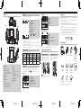
Dedicated App
The dedicated app “Dash Camera Interface” can be used to check the video recorded on this product or make settings
on the screen of an iPhone or Android device.
To use this app, a Wi-Fi connection must be made between this product and iPhone or Android device beforehand.
1 Set the Wi-Fi function of this product to on.
2 Operate the device to select this product as the Wi-Fi connection device.
The SSID name (access point name) and password of this product can be checked in the Wi-Fi settings screen.
• Only one device can be connected to this product at any one time. When a second device is connected, the first
device is disconnected.
• While a Wi-Fi connection is made, no operations can be performed on this product. If a function button is pressed
while a Wi-Fi connection is made, a message will be displayed prompting you to break the Wi-Fi connection. If you
select [Yes], the Wi-Fi connection will be disconnected, and operations on this product will be enabled.
• You can change the SSID name of this product by operating the dedicated app “Dash Camera Interface”. Note,
however, when the SD card is formatted, the SSID name returns to its default setting.
• It is recommended to enter the search term “Dash Camera Interface” in the search field to search for the application.
Dash Camera Interface
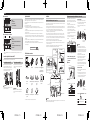
Check the Accessories
Main Unit×1 2nd Camera×1 Mounting Bracket×1 Power Cable
(5 m/16 ft. 5 in.)×1
Mini Pin Jack-RCA
Conversion Cable
(0.2 m/7-7/8 in.)×1
AV Cable
(5 m/16 ft. 5 in.)×1
2nd Camera
Connection Cable
(3 m/9 ft. 10 in.)×1*
2nd Camera
Connection Cable
(6 m/19 ft. 8 in.)×1*
microSDHC Card
(16 GB)×1
Quick Start Guide×1 Warranty×1 Cleaning Cloth×1
* The 2nd camera connection cable is included already connected.
■ During playback
56 78
5 Back
6 Next file
7 Previous file
8 Play/stop, delete
■ During MENU screen display
9a bc
9 Back
a Up*
Hold down to switch Wi-Fi on/off
b Down*
Hold down to switch microphone on/off
c Confirm
* When the volume or sensitivity MENU screen is displayed, increase or decrease the volume or sensitivity.
Inserting and Ejecting the microSD Card
Turn off the power to this product when inserting and removing the microSD card.
Inserting the microSD Card
Hold the top edge of the microSD card, position the
microSD card so that the label is facing the backside of
this product, and slowly insert it into the microSD card slot
until it clicks.
CAUTION
Do not insert the microSD card at an angle. Doing so
may cause damage.
Ejecting the microSD Card
Slowly push in the top edge of the microSD card until
it clicks (1). The lock will be released. Pull out the
microSD card (2).
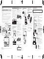
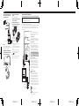
Part Names
b
9
4
a
d
3
5
1
6
2
c
87
e
f
Top
Front
Left side Right side
Back 2nd camera
1 AV Output Terminal
2 Power Port
Connect the power cable and AV cable.
3 2nd Camera Connection Terminal
Connect to the 2nd camera connection terminal
(e) using the 2nd camera connection cable.
4 microSD Card Slot
5 System Indicator
6 LCD
7 Function Buttons
8 Lens
Pioneer polarized filter AD-PLF100 (sold
separately) can help reduce reflections of the
dashboard onto the windshield, and enable the
capture of high-contrast videos.
9 Speaker
a Microphone
b Reset Button
Press this button with the tip of a ballpoint pen to
reset this product.
c Angle Adjustment Jog Dial
The angle of the lens can be adjusted by turning
this dial.
d Mounting Bracket
e Connection Terminal
f Lens
Status Display
The status display shows the operating status of this product.
00:00
12 3 54 6 7 8
1 Recording in progress
2 Elapsed recording time
3 Event recording status*1
4 Parking mode
5 Sound recording*2
6 Wi-Fi connection status*3
7 GPS reception status*4
8 Power status
( : Battery mode : Charging)
*1 When manual event recording is performed or vibration is detected in the event recording mode, and event
recording has been activated, “×2” is displayed.
*2 A red “\” is displayed when sound recording is set to off.
*3 During a Wi-Fi connection, this is displayed in green, and when Wi-Fi is disconnected, this is displayed in white. A
red “x” is displayed when Wi-Fi connection is set to off.
*4 During GPS reception, this is displayed in green, and when GPS cannot be received, this is displayed in white. In the
parking mode, a red “x” is displayed since GPS reception is set to off.
System Indicator Display
The operating status of this product is displayed with the system indicator.
System Indicator Menu Displayed/
During Playback Video Recording Recording Event
Error Has Occurred
(Including microSD
Card not Inserted)
Illuminated green ―○――
Illuminated red ――○―
Blinking red ―――○
Function Buttons
The functions of the function buttons are indicated by the icons displayed at the bottom of the screen.
The functions of the buttons will depend on the displayed screen. (Icons are not displayed on some screens.)
In the playback screen or MENU screen, pressing the function button returns you to the previous screen.
■ Recording
12 34
1 Main menu display
2 Switching of camera video
Hold down to switch Wi-Fi on/off
3 Manual recording of events
Hold down to switch microphone on/off
4 Take photo
English

CYR1298-A < 9 > CYR1298-A < 10 > CYR1298-A < 11 > CYR1298-A < 12 >
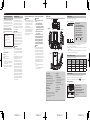
Installation
SpeciedInstallationPositiononFrontWindshield
When installing this product the inside of the front windshield, install in a vehicle and in a position that satisfies all of the
following conditions.
• A position where this entire product is within 20% of the top edge of the height of the front windshield (range within
20% of the actual length, excluding parts overlapping weatherstrips, mouldings, etc. and masked parts) or are in the
shadow of the rear view mirror as viewed from the driver’s seat.
Note that “20%” as described above is a rough estimate. Please install the product in accordance with your country’s
laws and regulations.
• If allowed by applicable law in your location, install in a 7-inch/17.8 cm square in the lower corner of the windshield
farthest from the driver, a 5-inch/12.7 cm square in the lower corner of the windshield nearest to the driver and outside
of any airbag deployment zone, or in a 5-inch/12.7 cm square mounted to the center uppermost portion of the interior
of the windshield. The ideal location is behind the rearview mirror out of the driver’s view as shown below.
• A position where the lens part of this product is within the wiping range of the wiper.
• A position where the lens part of this product does not hang over the sunshade and black ceramic lines/black ceramic
pattern.
• A position where this product faces in the horizontal direction to the front and side to side.
• A position where the power cable can be routed without unnecessary force.
Installation Direction
Horizontal Direction
Main Unit
Front Windshield
Ground
Main Unit
Horizontal Direction
Main Unit
Main Unit
*Install this product in a location
where it will not interfere with the
driver’s field of view,such as behind
the rear view mirror.
Installation Angle
Allowable Installation Angle:
30° to 60° (With Lens
Horizontal)
Front
Windshield
Forward Direction
of Vehicle
Within 20 % of Height
Rear View Mirror
Range of Windshield Wipers
A Pillar
A Pillar
AirBag
IMPORTANT
Always install this product in the specified installation position to ensure a safe field of view while driving and to achieve
full performance from the product.
Recommended Installation Position on Rear Windshield
When installing the 2nd camera on the inside of the rear
window, installation in a vehicle and in a position that
satisfies all of the following conditions is recommended.
• A position where the lens part of the 2nd camera is within
the wiping range of the wiper.
• A position where the 2nd camera faces in the horizontal
direction to the rear and side to side.
• A position where the lens part of the 2nd camera and the
double-sided tape do not overlap the heating wires.
• A position where the 2nd camera connection cable can
be routed without unnecessary force.
2nd camera
Rear windshield Connection cable
Heating wires
Wiping range of the rear wiper
1 Clean the installation area of dirt and oils
using the included cleaning cloth
■ Front windshield
■ Rear windshield
2 Install this product
①: Set the mounting bracket on this product.
②: Peel off the double-sided tape release paper from the
mounting bracket.
③: Install at the specified position of the front windshield.
2
1
3
Front
Windshield
Firmly push
this product.
CAUTION
• Make sure that the surface of the front windshield is dry
before applying the tape.
• Firmly push the area around the LCD. Next, remove this
product from the mounting bracket, and directly press
the mounting bracket against the tape. In this way, the
product can be firmly installed on the windshield.
• Never touch the surface of the LCD.
• Use extreme care as the double-sided tape on the
mounting bracket is extremely strong, and it will be
difficult to reapply the tape once it has been applied.
• To ensure the installation strength of the adhesive tape,
leave this product for 24 hours after application before
using it.
3 Install the 2nd camera
①: Peel off the double-sided tape release paper from the
2nd camera.
②: With the flat part shown in the figure facing up (position
where the △ mark on the side is facing up), install
the 2nd camera at the specified position on the rear
windshield.
12
Install with the flat
surface facing
upwards.
Face the lens towards the outside of the
car and firmly push.
4 Connect the power cable, 2nd camera
connection cable and AV cable to this
product
2nd camera
2nd camera connection cable
Power cable
AV Cable
Main Unit
Note
• Connecting the AV cable is only required if connecting
the VREC-DZ700DC to a compatible stereo with an
AV Input.
5 Route the power cable, 2nd camera
connection cable and AV cable to the
passenger seat side
Main Unit
2nd camera
Connection cable
6 Connect the power cable and AV cable
→
“Connecting the Power Cable”
7 Turn the vehicle engine on to display the
recording screen
8 Adjust the angle of the lens so that video
outside and inside the vehicle is properly
displayed
Turn the angle adjustment
jog dial to adjust the lens
angle.
Turn this part to adjust
the lens angle.
Before driving, turn the lens of this product towards
the outside of the vehicle.
This product restarts when the lens angle is moved
from the outside of the vehicle to the inside, and vice
versa.
To switch between camera video from this product
and video from the 2nd camera, press the
button. →
“Function Buttons”
Note
• A protective film is applied to the lens when the
product is purchased. Peel off this film.
Connecting the Power Cable
• Be sure to disconnect the ⊖ terminal of the vehicle’s battery before connecting the power cable.
• The product should be installed by authorized service company personnel who have special training and
experience with mobile electronics products.
The parking mode (security mode allowing 24-hour, 365-day surveillance) can be used by extracting power directly from
the vehicle by the power cable.
You can also connect the product to a head unit by using an AV cable and audio output mini pin jack-RCA conversion
cable so that you can check video footage and/or the camera view using the head unit screen.*
*Do not connect the product via AV cable unless the head unit displays video input only while the vehicle is parked.
Black 0.5 m/1 ft. 8 in.
Yellow 0.5 m/1 ft. 8 in.
Red 0.5 m/1 ft. 8 in.
4.5 m/
14 ft. 9 in.
Fuse
(F 2 AL/250 V)
Fuse
(F 2 AL/250 V)
0.2 m/
7-7/8 in.
Wiring specification of
this product
Audio is recorded in
monaural sound.
Audio (L)
Audio (R)
Ground
Video
Yellow Video
White Audio (L)
Red Audio (R)
Black 5 m/16 ft. 5 in.
Ground (Black)
Securely connect to the metal part of the vehicle body.
To prevent noise, connect as close to the navigation unit
as possible.
+ Battery power supply (Yellow)
Always connect to the power circuit supplied with power
from the battery, regardless of whether the vehicle
engine switch is ON or OFF.
Accessory power supply (Red)
Connect to the power circuit supplied with power when
the vehicle engine switch is turned to the ACC position.
Never install the accessory power supply to a vehicle
that does not have an ACC position on the engine switch.
Doing so may lead to a dead battery.
Note: Connect the red and yellow lead wires to
the terminals after wiring through the vehicle’s
fuse unit.
Video/audio output mini pin jack
Connect to the AUX input of the main unit of a Pioneer
product with a mini jack terminal compatible with video
input. Connection to main units of other brands with RCA
input terminals is also possible by using the included
mini pin jack-RCA conversion cable (figure below).
*After connecting, the following message is displayed:
“Is the 3.5mm Audio/Video Jack Connected?” Select
“Yes” or “No”.
Connection Precautions
To prevent fuming and damage to the product, be sure
to first securely connect the black lead wire (Ground)
of this product to the metal part of the vehicle body.
Connect separate black lead wires (Ground) for
products with a high current consumption such as a
power amplifier. When setting up connections all at once,
there is a risk of fuming or damage to the product when
screws loosen or come off completely.
Black lead wire (Ground)
Metal part of the vehicle body
*1
*1 Not supplied for this unit
English

CYR1298-A < 13 > CYR1298-A < 14 > CYR1298-A < 15 > CYR1298-A < 16 >
Afchagedel’état
L’affichage de l’état indique le fonctionnement de l’appareil.
00:00
12 3 54 6 7 8
1 Témoind’enregistrement
2 Affichagedutempsd’enregistrementécoulé
3 Affichagedustatutd’enregistrementd’événements*1
4 Affichage du mode stationnement
5 Affichage d’enregistrement audio*2
6 Affichage du statut de connexion Wi-Fi*3
7 AffichagedustatutderéceptionGPS*4
8 Affichagedel’étatdel’alimentation
( : Mode de batterie : Recharge)
*1 « ×2 » s’affiche si un enregistrement d’événement manuel est effectué pendant l’enregistrement d’événements ou si
des vibrations ont été détectées et que l’enregistrement d’événements a été lancé.
*2 Un « \ » rouge s’affiche si cette option est désactivée.
*3 S’affiche en vert pendant la connexion, et en blanc quand il n’y a pas de connexion. Un « × » rouge s’affiche si cette
option est désactivée.
*4 S’affiche en vert pendant la réception, et en blanc lorsque la réception n’est pas possible. Un « × » rouge s’affiche
en mode stationnement, puisque cette fonction est désactivée.
Afchagedutémoindusystème
L’état de l’appareil est confirmé par le témoin du système.
Témoindusystème
Pendant l’affichage
du menu /
Pendant la lecture
Pendant
l’enregistrement
vidéo
Pendant
l’enregistrement
d’événements
Lors d’une erreur
(y compris carte
microSD absente)
Allumé en vert ―○――
Allumé en rouge ――○―
Clignote en rouge ―――○
Touches de fonctions
Les fonctions des touches de fonctions sont indiquées par les icônes affichées au bas de l’écran.
Les fonctions varient selon l’écran affiché. (Sur certains écrans, les icônes ne s’affichent pas.)
Dans l’écran de lecture ou l’écran MENU, appuyez sur le bouton de fonction pour revenir à l’écran précédent.
■ Pendant l’enregistrement
12 34
1 Affichage du menu principal
2 Permutationdel’imagedecaméra
Appuyezlonguementpouractiver/désactiverleWi-Fi.
3 Enregistrementd’événementmanuel
Appuyezlonguementpouractiver/désactiverlemicrophone.
4 Prise de photos
Nomdespièces
b
9
4
a
d
3
5
1
6
2
c
87
e
f
Haut
Avant
Côtégauche Côtédroit
Arrière 2ecaméra
1 Borne de sortie AV
2 Brone d’alimentation
Branchez le câble d’alimentation / AV.
3 Borne de connexion de 2ecaméra
Branchez le câble de connexion de 2e caméra à la
borne de connexion de 2e caméra (e).
4 Emplacement pour carte microSD
5 Témoindusystème
6 Écran LCD
7 Touches de fonctions
8 Objectif
Le filtre polarisé AD-PLF100 de Pioneer (vendu
séparément) peut réduire les reflets du tableau de
bord sur le pare-brise et permettre la capture de
vidéos à contraste élevé.
9 Haut-parleur
a Microphone
b Touchederéinitialisation
Appuyez sur cette touche avec la pointe d’un stylo
à bille pour réinitialiser l’appareil.
c Molettederéglaged’angle
En le tournant, vous pouvez régler l’angle de
l’objectif.
d Support de montage
e Borne de connexion
f Objectif
Français
Précautionsàprendreavantderelierlesystème
AVERTISSEMENT
• Installez fermement cet appareil afin qu’il ne tombe
pas du pare-brise. Si cet appareil n’est pas fermement
installé, il peut tomber du pare-brise pendant la
conduite et provoquer un accident. Inspectez
périodiquement cet appareil.
• Pioneer recommande que seul le personnel autorisé
de la société de service, possédant une formation
et une expérience spécialisées en électronique
automobile, configure et installe cet appareil.
• Attachez tous les fils avec des collets ou des serre-
câbles. Ne laissez aucun fil à nu.
Précautionsàprendreavantl’installation
AVERTISSEMENT
• N’installez pas cet appareil dans un endroit où
il risque
(i) d’entraverlavisibilitéduconducteur,
(ii) d’altérerlefonctionnementdecertains
systèmesdecommandeoudedispositifsde
sécuritéduvéhicule,ycomprislescoussins
gonablesoulestouchesdefeuxdedétresse
ou
(
iii) d’empêcher le conducteur de conduire le
véhiculeentoutesécurité.
• N’installezjamaiscetappareildevantouàcôté
d’unendroitsurletableaudebord,uneportière
ouunpilier,àpartirduquelundescoussins
gonablesduvéhiculepourraientsedéployer.
Veuillez vous reporter au mode d’emploi du
véhiculepourensavoirplussurleszonesde
déploiementdescoussinsgonablesfrontaux.
ATTENTION
• Pour garantir une installation correcte, assurez-vous
d’utiliser les pièces incluses de la façon spécifiée.
Si certaines pièces ne sont pas incluses avec cet
appareil, utilisez des pièces compatibles de la façon
spécifiée après en avoir fait vérifier la compatibilité
par votre revendeur. Si d’autres pièces que les pièces
incluses ou compatibles sont utilisées, elles peuvent
endommager les pièces internes de cet appareil ou
être inapproprié, et l’appareil peut se détacher.
• N’installez pas cet appareil dans un endroit soumis
à des températures élevées ou à l’humidité. Par
exemple :
— À proximité du chauffage, de la ventilation ou de
la climatisation.
— À des endroits susceptibles d’être exposés à la
pluie, comme près de la porte..
Serviceaprès-ventedesappareils
Pioneer
Veuillez contacter le revendeur Pioneer agréé auprès
duquel vous avez acheté cette unité ou une société de
service après-vente Pioneer agréée ou les questions que
vous pourriez avoir sur l’appareil. Vous pouvez contacter
Pioneer directement comme suit :
N’expédiez pas votre appareil pour réparation
sans avoir d’abord contacté Pioneer. Les appareils
envoyés sans numéro d’autorisation de retour seront
refusés.
ÉTATS-UNIS ET CANADA
Pioneer Electronics (États-Unis) Inc.
CUSTOMER SUPPORT DIVISION
P.O. Box 1760
Long Beach, CA 90801-1760 États-Unis
800-421-1404
Pour obtenir plus d’informations sur la garantie, veuillez
consulter la feuille de garantie limitée inclus avec cette
unité.
Consultez notre site Web
États-Unis :
https://www.pioneerelectronics.com
Canada :
https://www.pioneerelectronics.ca
• Découvrez les mises à jour de l’appareil (telles que les
mises à jour du micrologiciel) pour votre appareil.
• Enregistrez votre appareil.
• Accédez modes d’emploi, aux informations sur les
pièces de rechange, aux informations de service et
bien plus encore.
Consignesdesécurité
Certaines lois nationales, étatiques et provinciales
peuvent interdire ou restreindre le placement et
l’utilisation de cet appareil dans votre véhicule. Veuillez
vous conformer à toutes les lois et réglementations
applicables concernant l’utilisation, l’installation et le
fonctionnement de cet appareil. Il incombe à l’utilisateur
de se conformer à toutes les lois, règles, réglementations
et ordonnances applicables.
AVERTISSEMENT
• N’installez pas l’appareil dans votre véhicule si son
emplacement ou son utilisation obstrue la vue du
conducteur sur la route ou le fonctionnement des
coussins gonflables du véhicule. Le conducteur doit
également s’assurer de connaître et respecter les
lois, règles et réglementations du lieu où il conduit, ce
qui inclut, par exemple, le droit de confidentialité des
passagers et l’interdiction d’utiliser l’appareil là où son
installation ou son utilisation est interdite.
AVERTISSEMENT
• Ne laissez pas cet appareil entrer en contact avec
des liquides. Ceci pourrait causer une électrocution.
En outre, le contact avec des liquides peut entraîner
des dommages, de la fumée et une surchauffe de
cet appareil.
Avant d’utiliser cet appareil, veuillez lire les consignes de
sécurité suivantes de manière à bien les comprendre :
• N’utilisez pas l’appareil si son utilisation vous
empêche, de quelque manière que ce soit, de
conduire votre véhicule en toute sécurité. Conduisez
toujours prudemment et respectez le code de la route
existant. Si vous rencontrez des difficultés lors de
l’utilisation de l’appareil ou de la lecture de l’écran,
garez votre véhicule en lieu sûr et serrez le frein à
main avant de procéder aux réglages nécessaires.
• Certaines fonctions (telles que l’affichage de l’écran et
certaines opérations sur les boutons) offertes par cet
appareil peuvent être dangereuses (pouvant entraîner
des blessures graves ou un décès) et/ou illégales si
elles sont utilisées pendant la conduite. L’affichage
à l’écran est désactivé pour cet appareil lorsque le
véhicule est en mouvement.

CYR1298-A < 17 > CYR1298-A < 18 > CYR1298-A < 19 > CYR1298-A < 20 >
Emplacementrecommandépourl’installationsurlavitrearrière
Lors de l’installation de la 2e caméra à l’intérieur de la
vitre arrière, l’installation dans un véhicule et dans un
emplacement qui remplit toutes les conditions suivantes
est recommandée.
• Un emplacement où l’objectif de la 2
e
caméra se
trouve dans la portée des essuie-glaces
• Un emplacement où la 2
e
caméra est orientée vers
l’arrière et les côtés en position horizontale
• Un emplacement où l’objectif de la 2
e
caméra et le
ruban adhésif double façe ne chevauchent pas les
fils thermiques.
• Un emplacement où le câble de connexion de la 2
e
caméra peut facilement atteindre la prise
2e caméra
Vitre arrière Câble de connexion
Fils thermiques
Portée de l’essuie-glace arrière
1 Utilisez le chiffon de nettoyage fourni
pourretirerlasaletéetl’huiledelazone
d’installation
■ Pare-brise
■Vitrearrière
2 Installez l’appareil
①: Réglez le support de montage sur cet appareil.
②: Décollez le papier protecteur du ruban antiadhésif
double face du support de montage.
③:Fixez-le à la position d’installation indiquée sur le
pare-brise.
2
1
3
Pare-brise
Appuyez fermement
sur cet appareil.
ATTENTION
• Ne le collez qu’une fois le pare-brise bien sec.
• Poussez fermement la zone autour de l’écran LCD.
Ensuite, retirez cet appareil du support de montage et
appuyez directement le support de montage contre le
ruban. De cette façon, l’appareil peut être fermement
installé sur le pare-brise.
• N’appuyez jamais sur la surface de l’écran LCD.
• Soyez extrêmement prudent, car le ruban adhésif
double face sur le support de montage est
extrêmement résistant et il sera difficile de déplacer
l’appareil une fois le ruban collé.
• Afin d’assurer toute la puissance d’adhésion du ruban
adhésif double face, n’utilisez le support d’installation
qu’au moins 24 heures après l’avoir fixé.
3 Installez la 2ecaméra
①: Retirez le film protecteur du ruban adhésif double
de sur la 2e caméra.
②: Avec la partie plate illustrée sur la figure orientée
vers le haut (position où le repère △ sur le côté
est orienté vers le haut), installez la 2e caméra à la
position spécifiée sur le pare-brise arrière.
1
2
Installez avec la
surface plane
orientée vers le haut.
Orientez l’objectif vers l’intérieur du
véhicule et appuyez fermement.
Installation
Positiond’installationindiquéesurlepare-brise
Lors de l’installation de cet appareil à l’intérieur du pare-brise avant, installez-le dans un véhicule et à un emplacement
remplissant toutes les conditions ci dessous.
• Un emplacement où l’ensemble de cet appareil se trouve à moins de 20 % du bord supérieur de la hauteur du pare-
brise avant (plage à moins de 20 % de la longueur réelle, à l’exclusion des pièces chevauchant des coupe-froid, des
moulures, etc., et des pièces masquées) ou à l’ombre du rétroviseur vu depuis le siège conducteur.
Notez que « 20 % », comme décrit ci-dessus, est une estimation approximative. Veuillez installer l’appareil
conformément aux lois et réglementations de votre pays.
• Si la loi en vigueur dans votre région l’autorise, installez dans un carré de 7 pouces/17,8 cm dans le coin inférieur
du pare-brise le plus éloigné du conducteur, un carré de 5 pouces/12,7 cm dans le coin inférieur du pare-brise le
plus proche du conducteur et à l’extérieur de toute zone de déploiement de coussins gonflables, ou dans un carré
de 5 pouces/12,7 cm monté sur la partie centrale la plus haute de l’intérieur du pare-brise. L’emplacement idéal est
derrière le rétroviseur hors de la vue du conducteur, comme illustré ci-dessous.
• Un emplacement où l’objectif de la caméra embarquée se trouve dans la portée des essuie-glaces.
• Un emplacement où la partie de l’objectif de cet appareil ne dépasse pas le pare-soleil et les lignes en céramique
noire/le motif en céramique noire.
• Un emplacement où la caméra embarquée est orientée vers l’avant et les côtés en position horizontale.
• Un emplacement où le câble d’alimentation peut être acheminé sans force inutile.
Sens d’installation
Sens horizontal
Unité
principale
Pare-brise
Sol
Unité principale
Sens horizontal
Unité principale
Unité principale
*Installez l’appareil à un emplacement
où il n’interférera pas avec le champ
de vision du conducteur (derrière le
rétroviseur, par exemple).
Angle d’installation
Angle d’installation
possible : 30° à 60° (avec
objectif à l’horizontale)
Pare-brise
FAvant du
véhicule
À 20 % de la hauteur
Rétroviseur
Portée des essuie-glaces
Montant A
Montant A
Coussin gonflable
IMPORTANT
Installez toujours l’appareil à l’emplacement d’installation indiqué pour garantir une vue sûre lors de la conduite et pour
bénéficier de performances optimales de l’appareil.
Applicationdédiée
L’application dédiée « Dash Camera Interface » peut être utilisée pour vérifier la vidéo enregistrée sur cet appareil ou
effectuer des réglages sur l’écran d’un iPhone ou d’un appareil Android.
Pour utiliser cette application, une connexion Wi-Fi doit être établie au préalable entre cet appareil et un iPhone ou un
appareil Android.
1 Activez la fonction Wi-Fi sur l’appareil.
2 Utilisez l’appareil pour sélectionner ce dernier comme périphérique de connexion Wi-Fi.
Il est possible de vérifier le nom SSID (nom de point d’accès) de l’appareil et le mot de passe sur l’écran de
réglages Wi-Fi.
• Un seul appareil peut être connecté à cet appareil à la fois. Lorsqu’un deuxième appareil est connecté, le premier
appareil sera déconnecté.
• Pendant la connexion Wi-Fi, il est impossible d’effectuer des commandes sur l’appareil. Si vous effectuez des
commandes sur les touches de fonctions pendant la connexion Wi-Fi, un message vous invitant à couper la connexion
Wi-Fi s’affichera. En sélectionnant [ Oui ], vous couperez la connexion Wi-Fi et vous pourrez effectuer des commandes
sur l’appareil.
• Il est possible de modifier le nom de SSID de l’appareil au moyen de l’application dédiée « Dash Camera Interface ».
Toutefois, le nom de SSID reviendra au réglage d’usine si vous formatez la carte SD.
• Il est recommandé d’entrer le terme de recherche «Dash Camera Interface » dans le champ de recherche pour
chercher l’application.
Dash Camera Interface
Véricationdesaccessoires
Unité principale×1 2e caméra×1 Support de montage×1 Câble d’alimentation (5 m)
× 1
Câble de conversion
miniprise-RCA (0,2 m) × 1
Câble AV
(5 m) × 1
Câble de connexion pour 2e
caméra
(3 m) × 1*
Câble de connexion pour 2e
caméra
(6 m) × 1*
Carte microSDHC
(16 Go) × 1
Guide de démarrage
rapide×1
Document de garantie × 1 Chiffon de nettoyage × 1
* Le câble de connexion pour 2e caméra (inclus) est déjà connecté.
■ Pendant la lecture
56 78
5 Retour
6 Fichier suivant
7 Fichierprécédent
8 Lecture/arrêt, supprimer
■ Pendantl’affichagedel’écranMENU
9a bc
9 Retour
a Vers le haut*
Maintenirenfoncépouractiver/désactiverleWi-Fi
b Vers le bas*
Maintenirenfoncépouractiver/désactiverlemicrophone
c Confirmation
* Lorsque l’écran MENU du volume ou de la sensibilité est affiché, cette touche augmente/réduit le volume ou la
sensibilité.
InsertionetéjectiondelacartemicroSD
Désactivez l’appareil avant l’insertion ou le retrait de la carte microSD.
Insertion de la carte microSD
Maintenez le bord supérieur de la carte microSD,
positionnez la carte microSD de manière à ce que
l’étiquette soit orientée vers l’arrière de l’appareil et
insérez doucement la carte dans l’emplacement pour
carte microSD jusqu’au déclic du verrou.
ATTENTION
N’insérez pas la carte microSD de façon inclinée. Ceci
pourrait endommager l’appareil.
Éjection de la carte microSD
Enfoncez doucement le bord supérieur de la carte
microSD jusqu’au déverrouillage (1). Retirez la carte
microSD (2).
ATTENTION
Le fait de retirer immédiatement votre doigt après le
déverrouillage de la carte microSD peut faire voler
celle-ci.
Français

CYR1298-A < 21 > CYR1298-A < 22 > CYR1298-A < 23 > CYR1298-A < 24 >
Raccordement du câble d’alimentation
• Raccordez toujours le câble d’alimentation après avoir déconnecté la borne ⊖ de la batterie du véhicule.
• L’appareil doit être installé par le personnel de la société de service autorisé qui a une formation et une expérience
spécifiques avec les appareils électroniques automobiles.
En alimentant l’appareil directement depuis le véhicule à l’aide du câble d’alimentation, vous pouvez utiliser le mode stationnement
(mode de sécurité permettant une surveillance 24h/24, 365 jours par année).
Vous pouvez également connecter l’appareil à une unité principale à l’aide d’un câble AV et d’un câble de conversion mini-jack RCA
de sortie audio afin de pouvoir vérifier les séquences vidéo et/ou la vue de la caméra à l’aide de l’écran de l’unité principale.*
*Ne connectez pas l’appareil via un câble AV à moins que l’unité principale n’affiche l’entrée vidéo uniquement lorsque
le véhicule est stationné.
Noir 0,5 m
Jaune 0,5 m
Rouge 0,5 m
4,5 m
Fusible
(F 2 AL/250 V)
Fusible
(F 2 AL/250 V)
0,2 m
Spécifications de
câblage de l’appareil
L’audio est enregistré
en mode mono.
Audio (G)
Audio (D)
Masse
Vidéo
Jaune Vidéo
Blanc Audio (G)
Rouge Audio (D)
Noir 5 m
Masse
Fixez fermement à la partie métallique de la carrosserie
du véhicule. Pour éviter le bruit, connectez le plus près
possible de la caméra embarquée.
Alimentation de batterie +
Connectez toujours au circuit d’alimentation qui est
alimenté par la batterie, peu importe que le commutateur
de démarrage du moteur du véhicule soit sur ON ou OFF.
Alimentation d’accessoire
Connectez au circuit d’alimentation qui est alimenté
lorsque le commutateur de démarrage du moteur du
véhicule est sur la position ACC. Ne connectez jamais
l’alimentation d’accessoire sur un véhicule qui n’a pas de
position ACC sur le commutateur de démarrage du
moteur. Cela peut entraîner l’épuisement de la batterie.
Remarque : Connectez les fils conducteurs rouge et
jaune aux bornes après les avoir fait passer par
un circuit protégé par une fusible.
Mini-prise de sortie vidéo/audio
Connectez-la à l’entrée AUX de l’unité principale d’un
appareil Pioneer équipé d’une borne de mini-prise
compatible avec l’entrée vidéo. La connexion à des
unités principales d’autres marques équipées de bornes
d’entrée RCA est également possible en utilisant un
câble de conversion mini-prise/RCA (figure ci-dessous).
*Après la connexion, le message suivant s’affiche : « La
prise audio/vidéo 3,5 mm est-elle reliée? » Sélectionnez
« Oui » ou « Non ».
Précautionsdeconnexion
Pour la formation de fumées et l’endommagement
de l’appareil, assurez-vous d’abord de connecter
fermement le fil de terre noir (Masse) de cet appareil
à une partie métallique de la carrosserie du véhicule.
Pour les appareils à forte consommation de courant,
tels qu’un amplificateur de puissance, connectez les
fils conducteurs noirs séparés (Masse). Lors de la mise
en place de connexions simultanées, il y a un risque de
formation de fumées ou d’endommagement de l’appareil
si les vis se desserrent ou se détachent complètement.
Fil conducteur noir (Masse)
Partie métallique de la carrosserie du véhicule
*1
*1 Non fourni avec cet appareil
4 Branchez le câble d’alimentation, le câble
de connexion de la 2ecaméraetlecâble
AVàlacaméraembarquée
2e caméra
Câble de connexion de 2e caméra
Câble d’alimentation
Câble AV
Unité principale
Remarques
• La connexion du câble AV n’est nécessaire que si
vous connectez la VREC-DZ700DC à un appareil AV
compatible et équipé d’une entrée AV.
5 Installez le câble d’alimentation, le câble
de connexion de la 2ecaméraetlecâble
AVsurlecôtédusiègepassager
Unité principale
2e caméra
Câble de connexion
6 Branchez le câble d’alimentation et le
câble AV
→
“Raccordement du câble d’alimentation”
7 Démarrezlemoteurduvéhiculeetactivez
l’écrand’enregistrement
8 Réglezl’angledel’objectifpourque
l’imagedel’intérieuroudel’extérieurdu
véhicules’affichecorrectement
Tournez l’angle de la
manette de réglage
d’angle pour ajuster
l’angle de l’objectif.
Tournez cette pièce
pour ajuster l’angle de
l’objectif.
Avant de conduire, tournez l’objectif de cet appareil
vers l’extérieur du véhicule.
l’appareil s’active lorsque vous déplacez l’angle de
l’objectif de l’extérieur vers l’intérieur du véhicule ou
vice-versa.
Pour basculer entre la vidéo de la caméra de cet
appareil et la vidéo de la 2e caméra, appuyez sur le
bouton . →
“Touches de fonctions”
Remarque
• Un film protecteur est appliqué sur l’objectif lors de
l’emballage du produit. Veuillez retirer le film.
Français
-
 1
1
-
 2
2
-
 3
3
-
 4
4
-
 5
5
-
 6
6


Pioneer VREC Mode d'emploi
- Taper
- Mode d'emploi
- Ce manuel convient également à
dans d''autres langues
- English: Pioneer VREC User guide
Documents connexes
-
Pioneer VREC-Z710DH Mode d'emploi
-
-
Pioneer VREC-Z710SH Guide de démarrage rapide
-
Pioneer VREC-DZ700DC Guide de démarrage rapide
-
Pioneer VREC-DZ600 Guide de démarrage rapide
-
Pioneer VREC-DH300D Guide de démarrage rapide
-
Pioneer VREC-170RS Manuel utilisateur
-
Pioneer VREC-DH200 Guide de démarrage rapide
-
Pioneer SPH-DA02 Manuel utilisateur
-