
User Manual
Cordless Screwdriver
Model: TDRT03P

English
Deutsch
Français
Español
Italiano
01~17
18~34
35~50
51~67
68~84
Contents
18 ~ 33
34 ~ 49
English------------------------------------------------ 01 ~ 17

- EN -
- 01 -
General Power Tool Safety Warnings
!WARNING Read all safety warnings and all instructions. Failure to follow the warnings
and instructions may result in electric shock, fire and/or serious injury.
SAVE ALL WARNINGS AND INSTRUCTIONS FOR FUTURE REFERENCE
Work area safety
Keep work area clean and well lit. Cluttered or dark areas invite accidents.Do not operate
power tools in explosive atmospheres, such as in the presence of flammable liquids, gases or
dust. Power tools create sparks which may ignite the dust or fumes. Keep children and
bystanders away while operating a power tool. Distractions can cause you to lose control.
Personal safety
Use personal protective equipment. Always wear eye protection. Protective equipment such
as dust mask, non-skid safety shoes, hard
hat, or hearing protection used for appropriate conditions will reduce personal injuries. Prevent
unintentional starting. Ensure the switch is in the off-position before connecting to power
source and / or battery pack, picking up or carrying the tool. Carrying power tools with your
finger on the switch or energizing power tools that have the
switch on invites accidents.
Remove any adjusting key or wrench before turning the power tool on. A wrench or a key left
attached to a rotating part of the power tool may result in personal injury.
Do not overreach. Keep proper footing and balance at all times. This enables better control of
the power tool in unexpected situations.
Dress properly. Do not wear loose clothing or jewelry. Keep your hair, clothing and gloves
away from moving parts. Loose clothes, jewelry or long hair can be caught in moving parts.
Power tool use and care
Do not force the power tool. Use the correct power tool for your application. The correct power
tool will do the job better and safer at the rate for which it was designed.
Disconnect the plug from the power source and/or the battery pack from the power tool before
making any adjustments, changing
accessories, or storing power tools. Such preventive safety measures reduce the risk of
starting the power tool accidentally.
Keep cutting tools sharp and clean. Properly maintained cutting tools with sharp cutting edges
are less likely to bind and are easier to control.
Service
Have your power tool serviced by a qualified repair person using only identical replacement
parts. This will ensure that the safety of the power tool is maintained.
Safety Rules for Rotary Tools
Safety warnings common for grinding, sanding, wire brushing,polishing, carving or abrasive
cutting-off operations:
This power tool is intended to function as a grinder, sander, wire brush, polisher,carving or
cut-off tool. Read all safety warnings, instructions, illustrations and specifications provided with
this power tool. Failure to follow all instructions listed below may result in electric shock, fire
and/or serious injury.
Do not use accessories which are not specifically designed and recommended by the tool
manufacturer. Just because the accessory can be attached to your power tool, it does not
assure safe operation.

- EN -
- 02 -
The RATED SPEED of the accessories must be at least equal to the operating speed setting
marked on the power tool. Accessories running faster than their RATED SPEED can break
and fly apart.
The outside diameter and the thickness of your accessory must be within the capacity rating
of your power tool. Incorrectly sized accessories cannot be adequately guarded or controlled.
The arbor size of wheels, sanding drums or any other accessory must properly fit the spindle
or collet of the power tool.Accessories that do not match the mounting hardware of the power
tool will run out of
balance, vibrate excessively and may cause loss of control.
Mandrel mounted wheels, sanding drums,cutters or other accessories must be fully inserted
into the collet or chuck. If the mandrel is insufficiently held and/or the overhang of the wheel is
too long, the mounted wheel may become loose and be ejected at high velocity.
Do not use a damaged accessory. Before each use inspect the accessory such as abrasive
wheels for chips and cracks,sanding drum for cracks, tear or excess wear, wire brush for loose
or cracked wires.
If power tool or accessory is dropped, inspect for damage or install an undamaged accessory.
After inspecting and installing an accessory, position yourself and bystanders away from the
plane of the rotating accessory and run the power tool at maximum no-load speed for one
minute. Damaged accessories will normally break apart during this test time.
Wear personal protective equipment.Depending on application, use face shield,safety goggles
or safety glasses. As appropriate, wear dust mask, hearing protectors, gloves and workshop
apron capable of stopping small abrasive or workpiece fragments. The eye protection
must be capable of stopping flying debris generated by various operations. The dust mask or
respirator must be capable of filtrating
particles generated by your operation. Prolonged exposure to high intensity noise may cause
hearing loss.
Keep bystanders a safe distance away from work area. Anyone entering the work area must
wear personal protective equipment.
Fragments of workpiece or of a broken accessory may fly away and cause injury beyond
immediate area of operation.
Hold the power tool by insulated gripping surfaces only, when performing an operation where
the cutting accessory may
contact hidden wiring or its own cord.Cutting accessory contacting a “live” wire may make
exposed metal parts of the power tool “live” and could give the operator an electric shock.
Always hold the tool firmly in your hand(s) during the start-up. The reaction torque of the motor,
as it accelerates to full speed, can cause
the tool to twist.
Use clamps to support workpiece whenever practical. Never hold a small workpiece in one
hand and the tool in the other hand while in use. Clamping a small workpiece allows you to use
your hand(s) to control the tool. Round material such as dowel rods, pipes or tubing have a
tendency to roll while being cut, and may cause the bit to bind or jump toward you.
Position the cord clear of the spinning accessory. If you lose control, the cord may be cut or
snagged and your hand or arm may be pulled into the spinning accessory.
Never lay the power tool down until the accessory has come to a complete stop.The spinning
accessory may grab the surface and pull the power tool out of your control.
After changing the bits or making any adjustments, make sure the collet nut, chuck or any
other adjustment devices are securely tightened. Loose adjustment devices can unexpectedly
shift, causing loss of control, loose rotating components will be violently thrown.

- EN -
- 03 -
Do not run the power tool while carrying it at your side. Accidental contact with the spinning
accessory could snag your clothing,pulling the accessory into your body.
Regularly clean the power tool’s air vents. The motor’s fan will draw the dust inside the
housing and excessive accumulation of powdered metal may cause electrical hazards.
Do not operate the power tool near flammable materials. Sparks could ignite these materials.
Do not use accessories that require liquid coolants. Using water or other liquid coolants may
result in electrocution or shock.
Use only in well-ventilated area. Working in a safe environment reduces risk of injury.
Allow for sufficient space, at least 6”,between your hand and the spinning bit. Do not reach in
the area of the spinning bit. The proximity of the spinning bit to your hand may not always be
obvious.
Do not touch the bit or collet after use. After use the bit and collet are too hot to be touched by
bare hands.
Do not alter or misuse tool. Any alteration or modification is a misuse and may result in serious
personal injury.
This product is not intended for use as a dental drill, in human or veterinary medical applica-
tions. Serious injury may result.
Kickback and Related Warnings
Kickback is a sudden reaction to a pinched or snagged rotating wheel, backing pad, brush or
any other accessory. Pinching or snagging causes rapid stalling of the rotating accessory
which in turn causes the uncontrolled power tool to be forced in the direction opposite of the
accessory’s rotation.
For example, if an abrasive wheel is snagged or pinched by the workpiece, the edge of the
wheel that is entering into the pinch point can dig into the surface of the material causing the
wheel to climb out or kickout. The wheel may either jump toward or away from the operator,
depending on direction of the wheel’s movement at the point of pinching. Abrasive wheels may
also break under these conditions.Kickback is the result of power tool misuse and/or incorrect
operating procedures or conditions and can be avoided by taking proper precautions as given
below.
Maintain a firm grip on the power tool and position your body and arm to allow you to resist
kickback forces. The operator can control kickback forces, if proper precautions are taken.
Use special care when working corners, sharp edges etc. Avoid bouncing and snagging the
accessory. Corners, sharp edges or bouncing have a tendency to snag the rotating accessory
and cause loss of control or kickback.
Do not attach a toothed saw blade. Such blades create frequent kickback and loss of control.
Always feed the bit into the material in the same direction as the cutting edge is exiting from
the material (which is the same direction as the chips are thrown). Feeding the tool in the
wrong direction causes the cutting edge of the bit to climb out of the work and pull the tool in
the direction of this feed.
When using rotary files, cut-off wheels, high-speed cutters or tungsten carbide cutters, always
have the work securely clamped. These wheels will grab if they become slightly canted in the
groove, and can kickback. When a cut-off wheel grabs, the wheel itself usually breaks. When
a rotary file, high-speed cutter or tungsten carbide cutter grabs, it may jump from the groove
and you could lose control of the tool.

- EN -
- 04 -
Safety warnings specific for grinding and abrasive cutting-off operations:
Use only wheel types that are recommended for your power tool and only for recommended
applications. For example: do not grind with the side of a cutoff wheel. Abrasive cut-off wheels
are intended for peripheral grinding, side forces applied to these wheels may cause them to
shatter.
For threaded abrasive cones and plugs use only undamaged wheel mandrels with an
unrelieved shoulder flange that are of correct size and length. Proper mandrels will reduce the
possibility of breakage.
Do not ƍƍMDPƍƍ a cut-off wheel or apply excessive pressure. Do not attempt to make an exces-
sive depth of cut. Overstressing the wheel increases the loading and susceptibility to twisting
or snagging of the wheel in the cut and the possibility of kickback or wheel breakage.
Do not position your hand in line with and behind the rotating wheel. When the wheel, at the
point of operation, is moving away from your hand, the possible kickback may propel the
spinning wheel and the power tool directly at you.
When wheel is pinched, snagged or when interrupting a cut for any reason, switch off the
power tool and hold the power tool motionless until the wheel comes to a complete stop. Never
attempt to remove the cut-off wheel from the cut while the wheel is in motion otherwise
kickback may occur.Investigate and take corrective action to eliminate the cause of wheel
pinching or snagging.
Do not restart the cutting operation in the workpiece. Let the wheel reach full speed and
carefully re-enter the cut. The wheel may bind, walk up or kickback if the power tool is restart-
ed in the workpiece. Support panels or any oversized workpiece to minimize the risk of wheel
pinching and kickback. Large workpieces tend to sag under their own weight. Supports must
be placed under the workpiece near the line of cut and near the edge of the workpiece on both
sides of the wheel.
8VHH[WUDFDXWLRQZKHQPDNLQJDƍƍSRFNHWFXWƍƍLQWRH[LVWLQJZDOOVRURWKHUEOLQGDUHDV
The protruding wheel may cut gas or water pipes, electrical wiring or objects that can cause
kickback.
Safety warnings specific for wire brushing operations:
Be aware that wire bristles are thrown by the brush even during ordinary operation. Do not
overstress the wires by applying excessive load to the brush. The wire bristles can easily
penetrate light clothing and/or skin.
Allow brushes to run at operating speed for at least one minute before using them. During this
time no one is to stand in front or in line with the brush. Loose bristles or wires will be
discharged during the run-in time.
Direct the discharge of the spinning wire brush away from you. Small particles and tiny wire
fragments may be discharged at high velocity during the use of these brushes and may
become imbedded in your skin.
Additional Safety Warnings
! WARNING Do not use router bit with the ijijPP chuck. Bit may become a projectile
and cause serious injury.
GFCI and personal protection devices like electrician’s rubber gloves and footwear will further
enhance your personal safety.
Keep handles dry, clean and free from oil and grease. Slippery hands cannot safely control the
power tool.
Use clamps or other practical way to secure and support the workpiece to a stable platform.
Holding the work by hand or against your body is unstable and may lead to loss of control.

- EN -
- 05 -
Develop a periodic maintenance schedule for your tool. When cleaning a tool be careful not to
disassemble any portion of the tool since internal wires may be misplaced or pinched or safety
guard return springs may be improperly mounted. Certain cleaning agents such as gasoline,
carbon tetrachloride, ammonia, etc. May damage plastic parts
! WARNING Some dust created by power sanding, sawing,
grinding, drilling, and other construction activities contains chemicals known to cause cancer,
birth defects or other reproductive harm. Some examples of these chemicals are:
Ɣ
Ɣ
Symbols
Lead from lead-based paints,
Crystalline silica from bricks and cement and other masonry products, and Arsenic and
chromium from chemicallytreated lumber.
Your risk from these exposures varies, depending on how often you do this type of work. To
reduce your exposure to these chemicals: work in a well ventilated area, and work with
approved safety equipment, such as those dust masks that are specially designed to filter
out microscopic particles.
Designation / Explanation
Volts (voltage)
Amperes (current)
Hertz (frequency, cycles per second)
Diameter (size of drill bits, grinding wheels, etc.)
Class II construction (designates double insulated construction tools)
Designates Li-ion battery recycling program
Alerts user to read manual
Alerts user to wear eye protection
Symbol
V
A
Hz

- EN -
- 06 -
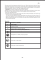
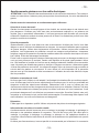
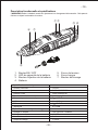
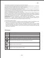
Functional Description and Specifications
! WARNING Remove the power pack before making any assembly, adjustments or changing
accessories. Such preventive safety measures reduce the risk of starting the tool accidentally.
ON/OFF switch
battery capacity LED
battery remove button
power pack
Console Technical Specifications
Rated Voltage
Capacity
No load speed
Chuck clamping range
Sound pressure level
(A)Uncertainty
Sound power level
(A)Uncertainty K
Charge Technical Specifications
Input Rated Voltage
Output Voltage
Output current
Charge time
12VDC
2.0Ah LIHIUMION
5000-25000RPM
ijPPijPP
L
DA
=40.5dB
K
DA
=3dB
L
WA
=71.5dB
K
WA
=3dB
100-120V AC 50/60Hz
12V DC
2.1A
1hour
1.
2.
3.
4.
tensioning nut
Cap nut
shaft lock button
5.
6.
7.
ŝ
Ś ś
Ŝ
ş
Ş
Š

- EN -
- 07 -
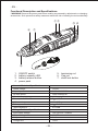
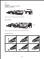
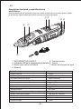
Operation specification
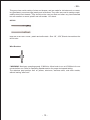
The power pack install and remove
Install power pack
Ensure the groove of console is compatible with the groove of battery
Remove power pack form console
Press remove button on both sides of battery, don’t release untill pull the battery out.
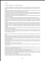
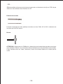
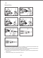
Operation instruction for collet changing
1
2
1 2 3
4 5 6

- EN -
- 08 -
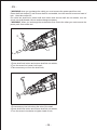
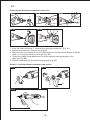
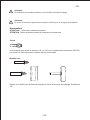
! WARNING when you exchange the collet,you must remove the power pack from tool.
Press shaft lock button(7) and ensure shaft do not wobble, turn the wrench to remove head of
lock , then take collet out;
Put collet into shaft hole, press shaft lock button and ensure shaft do not wobble, turn the
chuck into shaft thread; remove and exchange accessory
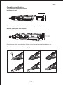
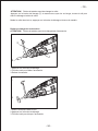
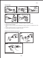
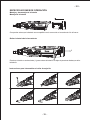
! WARNING When you exchange the accessories from one to the other,you must remove the
power pack from rotate tool.
1.Press shaft lock button and ensure shaft do not wobble;
2.Turn the wrench to loosen lock head ;
3.Take accessory out from the shaft hole;
1.Put accessory into hole along the axis of the shaft;
2.Press shaft lock button and ensure shaft do not wobble;
3.Turn the wrench clockwise to tighten head of lock;
1
2
3

- EN -
- 09 -
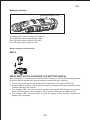
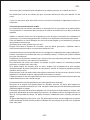
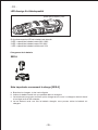
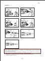
Battery indicator
In working state, battery indicator LED light on.
3pcs LED light: battery capacity 60%-100%
2pcs LED light: battery capacity 33%-60%
1pc LED light: battery capacity< 33%
Battery charger under working
SEE A
IMPORTANT NOTES CHARGING THE BATTERY [SEE A]
On the type plate, the product and in this instruction manual you can find the following symbols
and signs. Before operating the product acquaint yourself with their meaning:
a.
b.
c.
d.
Connect the power cord of the charger with a wall socket. The green LED Twinkle.
Slide the battery as far as it will go into the charger, by inserting the battery terminal into the
suitable opening of the charger.
The charging LED turn red to show the charge has started, The charger may become
warm and buzz slightly during charging. This is normal, and does not indicate a fault.
The charging LED turn green again to show the battery is fully charged. Remove the
battery from the charger.
power pack capacity LED

- EN -
- 10 -
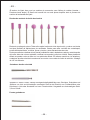
Accessory introduce
! WARNING When you use as below these accessory for work, you must wear eye protec-
tion.
! WARNING When you exchange the accessories from one to the other,you must remove the
power pack from rotate tool.
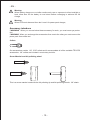
Collets
Our accessories contain 1/8", 3/32" collets and it accommodate all of the available TECCPO
accessories. 1/8" collets are included in most rotary tool kits.
Screw Mandrel and felt polishing wheel
This is a screw mandrel used with the felt polishing tip and felt polishing wheels. 1/8" shank.
Warning:
When battery charge runs out after continuously use or exposure to direct sunlight or
heat, allow time for the battery to cool down before recharging to achieve the full
charge;
Warning:
When LED work abnormal then don’t use it for power pack charger;

- EN -
- 11 -
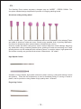
Small Screw Mandrel ,sanding paper and cut off wheel
This is a mandrel with a small screw at its tip,and is used with emery and fiberglass cutting
wheels, sanding discs and polishing wheels.1/8" shank.
! WARNING for fiberglass cutting wheel use: do not have people in the direction of cutting;
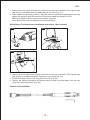
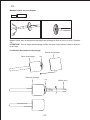
4-Sanding Drum and sanding band use
sanding dium
sanding band
screw
sanding dium
screw
screw bit

- EN -
- 12 -
The Sanding Drum makes accessory changes easy as INSERT - PRESS DOWN. The
one-piece mandrel design simplifies the process of changing sanding bands
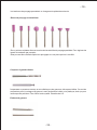
Aluminam oxide grinding wheel
Round, pointed, flat — you name the shape and there is one available in this category.These
are made of aluminum oxide and cover virtually every possible kind of grinding application.
Use them for sharpening lawn mower blades, screwdriver tips, knives,
scissors, chisels and other cutting tools. Use to remove flash from metal castings, deburring
any metal after cutting, smoothing welded joints, grinding off rivets and removing rust. These
grinding stones can be resharped with a dressing stone. In machine shops, high speed drills
and cutters normally are ground with aluminum oxide wheels. 1/8" shank.
High Speed Cutters
Available in many shapes, high speed cutters are used in carving, cutting and slotting in wood
and plastics . These are the accessories to use for freehand routing or carving in wood or
plastic, and for precision cutting. Made of high quality steel. 1/8"shank
Engraving Cutters

- EN -
- 13 -
This group has a wide variety of sizes and shapes, and are made for intricate work on ceram-
ics (greenware), wood carvings,jewelry and scrimshaw. They often are used in making compli-
cated printed circuit boards. They should not be used on steel and other very hard materials
but are excellent on wood, plastic and soft metals. 1/8" shank.
drill bit
HSS drill bit for use in wood , plastic and soft metals . Size 1/8” , 3/32”,Shank size matches the
drill bit size.
Wire Brushes
! WARNING Maximum operating speed 15,000/min. Allow brush to run at 15,000/min for one
minute before use. Refer to Operating Speeds section for proper tool speed setting.
The stainless steel perform well on pewter, aluminum, stainless steel, and other metals,
without leaving "after-rust".

- EN -
- 14 -
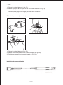
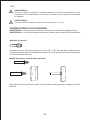
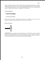
Cutting Guide Attachment Installation Instruction
1.
2.
3.
4.
5.
Detailer’s Grip Attachment Installation Instructions
Press the Shaft lock button 1, unscrew and remove the collet nut 2 (Fig. B1).
Unscrew the nose cap 3 from the tool (Fig.B2).
Place the collet nut 2 loosely on the end of the rotary tool and insert the cutting bit 4.Tighten
collet nut 2 using the wrench or nose cap (Fig. B3).
Thread the Cutting Guide Attachment 5 onto the exposed housing threads on the
rotary tool (Fig. B4).
Adjust the attachment to the desired cutting depth (Fig. B5).
FIG. B4
FIG. B5
1
2
3
2
4
FIG. B1 FIG. B2
FIG. B3
FIG. F1
FIG. F2
FIG. F3
A
B
C
D

- EN -
- 15 -
1.
2.
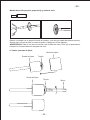
Shield Rotary Tool Attachment Installation Instructions (Not included)
1.
2.
3.
Flexible shaft installation
FIG. D1
A
B
C
C
FIG. D2
FIG. D3
Remove the nose cap A from the end of the tool and set nose cap aside. The original nose
cap must be reinstalled when this attachment is not used (Fig. F1).
Place handle B over housing collar C with the handle in the desired position and securely
tighten the handle B with the nose piece D that’s provided with handle (Fig.F2).
Make sure detailer’s grip is fully secured before using tool.
Note: Attachment may not install flush ontotool's housing.
Remove the nose cap A from the end of the tool and set nose cap aside. The original nose
cap must be re-installed when this attachment is not used (Fig. D1).
Screw the Shield onto the tool using the lock nut B (Fig. D2)
Position the Shield such that it will redirect debris, sparks, and dust away from the user
using the positioning tabs C (Fig. D3).

- EN -
- 16 -
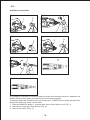
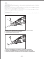
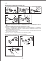
Installation Instructions
It is extremely important to carefully read and follow the directions below to assemble the
Flexible Driver to your rotary to ensure the tool will function properly.
To properly attach the Flexible Driver to the rotary tool, THREE items must be removed from
the tool: the nose cap, collet nut and collet.
1.
2.
3.
Press the Shaft lock button 1, unscrew and remove the collet nut or 2 (Fig. 1).
Unscrew the nose cap 3 from the tool (Fig. 2).
Remove the collet 4 (Fig. 3).
Fig.1 Fig.2
Fig.4
Fig.6
Fig.3
Fig.5
Fig.7
Rotary
Tool
RTD36AC
5
6
Rotary
Tool
RTD36AC
3
Rotary
Tool
RTD36AC
4
Rotary
Tool
RTD36AC
1
2
Rotary
Tool
RTD36AC
7

- EN -
- 17 -
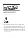
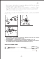
4.
5.
6.
7.
Cleaning, maintenance
Always remove the power pack before starting any cleaning work.
Cleaning.
Keep all safety devices, air vents and the motor housing free of dirt and dust as far as
possible. Wipe the equipment with a clean cloth or blow it with compressed air at low pressure.
We recommend that you clean the device immediately each time you have finished using it.
Clean the equipment regularly with a moist cloth and some soft soap.
Do not use cleaning agents or solvents; these could attack the plastic.
parts of the equipment. Ensure that no water can seep into the device.
Maintenance
There are no parts inside the equipment which require additional maintenance.
Environmental Protection
Install the driver cap 5 on the motor shaft 6 and tighten (Fig. 4). To prevent damage to tool,
do not over tighten driver cap. Tighten the driver cap finger tight and then tighten an
additional 1/3 turn with the wrench.
Attach by screwing the collar of the Flexible Driver 7 to the rotary tool.
Make sure the square end of the center core engages the square hole socket in the driver
cap (Fig. 5).
Insert the “L” pin 8 and fix the shaft, loose the quick chuck (Fig. 6)
Insert the accessories into quick chuck and tighten it. (Fig. 7)
When using Flexible Driver, it is recommended that the diameter of the accessories can't
exceed 3.2MM
I
Waste electrical products should not be disposed of with household waste. Please
recycle where facilities exist. Check with your Local Authority or retailer for recycling
advice.
FCC Caution
This device complies with part 15 of the FCC rules. Operation is subject to the following two
conditions:
1. This device may not cause harmful interference.
2. This device must accept any interference received, including interference that may cause
undesired operation.

- FR -
- 35 -
Avertissements généraux sur les outils électriques
ATTENTION ! Lisez l’ensemble des avertissements de sécurité et des instructions. Tout manque-
ments aux instructions ci-dessous peut provoquer des chocs électriques, feu et/ou des blessures
graves.
Gardez toutes les instructions et avertissements pour références
Sécurité de la zone de travail
Gardez l’environnement de travail propre et bien éclairé, les endroits sales et mal éclairés sont
plus dangereux. N’utilisez pas l’outil dans des environnements explosifs ou en présence de
liquides, gaz ou poussières inflammables. L’outil peut provoquer des étincelles qui pourrait les
enflammer. Gardez les enfants et autres personnes à l’écart. Les distractions peuvent vous faire
perdre le contrôle de la situation.
Sécurité personnelle
Restez attentifs à ce que vous faites et à votre environnement. N’utilisez pas l’outil si vous êtes
fatigues ou sous l’influence de médicaments ou drogues. Un moment d’inattention peut engendrer
de graves dangers. Utilisez des équipements de protection. Utilisez toujours des lunettes de
protection. Les équipements de protection comme les masques anti-poussières, chaussures
antiglisse, casques de protection et protection auditives aident à la réduction des risques s’ils sont
bien utilisés. Evitez les démarrages accidentels
Porter l’outil en ayant le doigt sur le bouton d’allumage peut provoquer un allumage soudain et non
voulu qui peut provoquer un accident. Gardez votre équilibre et les pieds à plat pendant l’utilisa-
tion. Cela améliore le contrôle de l’outil en cas de situation inattendue. Habillez-vous convenable-
ment. Ne portez pas d’habits trop grands ou de bijoux. Eloignez vos cheveux, vêtements et gants
à l’écart des parties en mouvement. Les vêtements amples, bijoux et cheveux longs pourraient se
coincés dans les parties en mouvement. Si vous utilisez un outil d’aspiration de la poussière
assurez-vous qu’il est branché et utilisé correctement. L’utilisation de ces outils réduit les risques
liés à la poussière.
Utilisation et entretien de l’outil
Ne forcez pas l’outil. Utilisez un outil adapté. L’outil adapté à la situation offre une meilleure expéri-
ence. N’utilisez pas l’outil si le bouton marche/arrêt ne fonctionne pas. Un outil non contrôlable est
dangereux et doit être réparé avant utilisation. Débranchez l’outil si vous ne l’utilisez pas. Les
risques seront réduits lors des changements d’embouts et de la non utilisation. Stockez l’outil hors
de portée des enfants et ne laissez pas quelqu’un utiliser l’outil sans voir lu les instructions. L’outil
peut devenir dangereux s’il est utilisé par une personne non avisée. Surveillez l’état de votre outil,
les parties en mouvement et qui peuvent être endommagées. Si endommagé faite réparer l’outil
avant utilisation. Les outils non entretenus sont dangereux.
Réparation
Faites appel à un réparateur qualifié. Utilisez uniquement des pièces de rechanges originales.
Information de sécurité sur les outils rotatifs
Avertissements de sécurité communs pour le meulage, le ponçage, le balayage, le polissage, la
découpe ou les opérations abrasive et coupantes : Cet outil est conçu pour être utilisé pour le
meulage, le ponçage, le balayage, le polissage, la découpe ou les opérations abrasive et
coupantes. Lisez toutes les instructions de sécurité, les illustrations et les spécifications du produit
fournies.
N’utilisez pas d’accessoires qui ne sont pas fait et recommandés par le fabricant. Un accessoire
- 18 -
La page charge ...
La page charge ...
La page charge ...
La page charge ...
La page charge ...
La page charge ...
La page charge ...
La page charge ...
La page charge ...
La page charge ...
La page charge ...
La page charge ...
La page charge ...
La page charge ...
La page charge ...
La page charge ...
La page charge ...
La page charge ...
La page charge ...
La page charge ...
La page charge ...
La page charge ...
La page charge ...
La page charge ...
La page charge ...
La page charge ...
La page charge ...
La page charge ...
La page charge ...
La page charge ...
La page charge ...
La page charge ...
La page charge ...
-
 1
1
-
 2
2
-
 3
3
-
 4
4
-
 5
5
-
 6
6
-
 7
7
-
 8
8
-
 9
9
-
 10
10
-
 11
11
-
 12
12
-
 13
13
-
 14
14
-
 15
15
-
 16
16
-
 17
17
-
 18
18
-
 19
19
-
 20
20
-
 21
21
-
 22
22
-
 23
23
-
 24
24
-
 25
25
-
 26
26
-
 27
27
-
 28
28
-
 29
29
-
 30
30
-
 31
31
-
 32
32
-
 33
33
-
 34
34
-
 35
35
-
 36
36
-
 37
37
-
 38
38
-
 39
39
-
 40
40
-
 41
41
-
 42
42
-
 43
43
-
 44
44
-
 45
45
-
 46
46
-
 47
47
-
 48
48
-
 49
49
-
 50
50
-
 51
51
-
 52
52
-
 53
53


dans d''autres langues
- English: TECCPO TDRT03P User manual
- español: TECCPO TDRT03P Manual de usuario
Documents connexes

Autres documents
-
Arrow ROT3200K-A Manuel utilisateur
-
Dremel 9100 Manuel utilisateur
-
 HART HPRL01 Le manuel du propriétaire
-
Milwaukee 2460-20-2441-20-48-11-2460 Manuel utilisateur
-
Dremel 4300-5/40 Manuel utilisateur
-
-
Ryobi PCL480 Manuel utilisateur
-
-
Ryobi PBLRT01B Le manuel du propriétaire
-
