QSC DAB-801 Manuel utilisateur
- Catégorie
- Matériel musical
- Taper
- Manuel utilisateur

Hardware Installation Manual
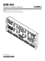
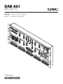
DAB-801 – DataPort amplifier backup, 8-channels
Q-Sys
TM
Amplifier and I/O Frame Backup Accessory
*TD-000292-00*
TD-000292-00-A
DAB-801

2
EN
3
IMPORTANT SAFETY PRECAUTIONS AND EXPLANATION OF SYMBOLS
WARNING!
All products manufactured by QSC Audio Products, LLC are designed for safe operation, and have been certified by recognized product safety
agencies to meet all normal standards for this type of product. However, dangerous voltages and power levels exist within the covers of
this DataPort Amplifier Relay Panel. The user is requested to study the precautions in this manual. If the product has been dropped, dented,
soaked, or appears to have loose parts inside, the risk of shock is increased. Unplug the AC cord, and take the product to qualified service
personnel for inspection and repairs. Consult a licensed, Professional Engineer regarding physical equipment installation. Ensure that all local,
state and national regulations regarding the safety and operation of suspended equipment are understood and adhered to.
SUPPORT AND SERVICE
QSC Audio Products, LLC maintains a world-wide network of distributors and service centers. These local agencies will be able to answer your
questions and take care of any problems.
Read these instructions.1.
Keep these instructions.2.
Heed all warnings.3.
Follow all instructions.4.
WARNING: To prevent fire or electric shock, do not expose this equipment to rain or moisture. Do not use this apparatus near water.5.
Clean only with a dry cloth.6.
Do not block any ventilation openings. Install in accordance with the manufacturer’s instructions.7.
Do not install near any heat sources such as radiators, heat registers, stoves, or other apparatus that produce heat.8.
The appliance coupler is the AC mains disconnect and should remain readily operable after installation.9.
Do not defeat the safety purpose of the grounding-type plug. A grounding plug has two blades and a grounding prong. The wide blade 10.
or third prong are provided for your safety. If the provided plug does not fit your outlet, consult an electrician for the replacement of the
obsolete outlet. This apparatus should be connected to a receptacle with a protective earthing (or ground) connection.
Protect the power cord from being walked on or pinched, particularly at plugs, convenience receptacles, and the point where they exit 11.
from the apparatus.
Use only attachments/accessories specified by QSC Audio Products, LLC.12.
Use only with hardware, brackets, stands, and components sold with the apparatus or by QSC Audio Products, LLC.13.
Unplug the apparatus during lightning storms or when unused for long periods of time.14.
Refer all servicing to qualified service personnel. Servicing is required when the apparatus has been damaged in any way, such as power 15.
supply cord or plug is damaged, liquid has been spilled or objects have fallen into the apparatus, the apparatus has been exposed to rain
or moisture, does not operate normally, or has been dropped.
The lightning flash with the arrowhead symbol within an equilateral triangle is intended to alert the user to the presence of
uninsulated “dangerous” voltage within the product’s enclosure that may be of sufficient magnitude to constitute a risk of shock
to humans.
The exclamation point within an equilateral triangle is intended to alert the user to the presence of important operation and mainte-
nance (servicing) instructions in this manual.
CAUTION: TO REDUCE THE RISK OF ELECTRIC SHOCK, DO NOT REMOVE THE COVER. NO USER-SERVICEABLE PARTS INSIDE. REFER
SERVICING TO QUALIFIED PERSONNEL.

2
3
EN
Warranty (USA only; other countries, see your dealer or distributor)
Disclaimer
QSC Audio Products, LLC is not liable for any damage to this Relay Panel or any other equipment that is caused by negligence or improper installa-
tion and/or use of this product.
QSC Audio Products 3-Year Limited Warranty
QSC Audio Products, LLC (”QSC”) guarantees its products to be free from defective material and/or workmanship and will replace defective parts
and repair malfunctioning products under this warranty when the defect occurs under normal installation and use-provided the unit is returned to
our factory, one of our authorized service stations or an authorized QSC International Distributor via pre-paid transportation with a copy of proof of
purchase (i.e., sales receipt). This warranty provides that the examination of the return product must indicate, in our judgment, a manufacturing defect.
This warranty does not extend to any product which has been subjected to misuse, neglect, accident, improper installation, or where the date code
has been removed or defaced. QSC shall not be liable for incidental and/or consequential damages. This warranty gives you specific legal rights. This
limited warranty is freely transferable during the term of the warranty period. The warranty on QSC products is NOT VALID if the products have been
purchased from an unauthorized dealer/online e-tailer, or if the original factory serial number has been removed, defaced, or replaced in any way.
Damage to, or loss of any software or data residing on the product is not covered. When providing repair or replacement service, QSC will use reason-
able efforts to reinstall the product’s original software configuration and subsequent update releases, but will not provide any recovery or transfer of
software or data contained on the serviced unit not originally included in the product.
Customers may have additional rights, which vary from state to state or from country to country. In the event that a provision of this limited warranty is
void, prohibited or superseded by local laws, the remaining provisions shall remain in effect.
Periodically, this warranty is updated. To obtain the most recent version of QSC’s warranty statement, please visit www.qscaudio.com.
Contact us at 800-854-4079 or visit our website at www.qscaudio.com.
The QSC limited warranty is valid for a period of three (3) years from date of purchase in the United States and many (but not all)
other countries.
For QSC warranty information in countries other than the United States, contact your authorized QSC international distributor. A list of QSC International
distributors is available at www.qscaudio.com.
To register your QSC product online, go to www.qscaudio.com and select ”Product Registration.” Other questions regarding this warranty can be
answered by calling, e-mailing or contacting your authorized QSC distributor.
© 2009, QSC Audio Products, LLC.
Patents may apply or be pending.
QSC is a registered trademark of QSC Audio Products, LLC.
“QSC” and the QSC logo are registered with the U.S. Patent and Trademark Office.
All trademarks are the property of their respective owners.

4
EN
5
Introduction
Thank you for your purchase of the DAB-801 Q-Sys
TM
amplifier backup system. In order to insure correct operation in the unlikely event of amplifier or
Q-Sys
failure, we recommend you review all the information provided in this Installation Manual.
The DAB-801 extends Q-Sys backup capability to include designated QSC power amplifiers and I/O Frames populated with CODP4 cards. The
DAB-801 adds the ability to add N+1 amplifier redundancy to any system for up to 8 channels, as well as the ability to automatically switch all DataPort
connected amplifiers from a primary I/O Frame to a backup I/O Frame.
The DAB-801 is easily integrated into a Q-Sys based audio system. Mounted in the rear of a rack, the DAB-801 minimizes rack space consumption. AC
line connection is fast and easy; an IEC-style quick-disconnect with locking bracket ensures reliable AC mains connection. A one world power supply
operates on 100-240VAC, 50/60Hz. By using QSC standard HD-15 DataPort connectors and high current detachable terminal blocks, the DAB-801
provides an easy to install connector set. Two D-Sub 15 pin connections allow direct connection to a pair of I/O Frames for control and monitoring
of the DAB-801. Two paging modes are available for high priority paging and are activated with either a standard contact closure or +12VDC trigger
voltage. Two DAB-801 panels may be combined using the included 37 pin cable for 16 total channels of I/O Frame and N+1 redundancy.
Various LED indicators alert the user to current panel status. The LEDs include an AC power indicator, I/O Frame power status indicators, amplifier
power status indicators, I/O Frame failure indicators, and amplifier failure indicators.
Download the latest version of Q-Sys software to insure that your system will work with this accessory.
Glossary
AC Mains – The AC voltage present at a wall socket or outlet.
Backup – The redundant item in a fault-resistant system. If the primary item fails, the backup item replaces the primary item, restoring full
system operation.
CODP4 – QSC output card designed to mount internally in an I/O-Frame. Connects to 2 DataPort equipped amplifiers or a single
4-channel amplifier.
D-Sub (or DB) – A type of cabling connector whose outer shell is shaped like the capital letter D. DB type connectors have two individual
rows of pins.
DataPort – A proprietary QSC connection featured on many of our installation and touring amplifiers. Uses a HD-15 type connector.
Extension Panel – An identical DAB-801 that is connected to a master DAB-801 bringing the total system channel capability up to
16 audio channels.
Fault-tolerant – A system that continues operation, possibly at a reduced level, rather than failing completely, when some part of the system fails.
GPIO – An acronym that stands for General Purpose Input and Output.
HD15 – A high density type of cabling connector whose outer shell is shaped like the capital letter D. HD type connectors have three individual rows
of pins. The “15” indicates the total number of pins in the connector.
IEC Socket – A standard type of AC mains connector used in most consumer equipment.
I/O Frame – QSC hardware used to input and output audio signals from a Q-Sys system.
N+1 Redundancy – A system that has “N” items and a single backup item. If any single item fails, the system automatically replaces that item with the
backup. In the case of the DAB-801, amplifiers are redundant in this manner.
Primary I/O Frame – The main I/O Frame in a fault-resistant system. If the primary I/O Frame fails, the backup item will automatically restore full
system operation.
Q-Sys
TM
– QSC Audio’s proprietary system solution.

4
5
EN
How It Should Be Used
The DAB-801 must be used as part of a Q-Sys
TM
system. As such the DAB-801 cannot be used with any other control system. Furthermore, the
DAB-801 interfaces to QSC DataPort equipped amplifiers only.
Every amplifier connected to the DAB-801 must be the same model; the DAB-801 does not support mixing amplifier models.
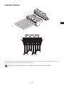
Rack Mounting
The DAB-801 mounts in the rear of a rack. Use four screws and washers to mount the DAB-801 to the rear rack rails. The DAB-801 can be mounted •
in the front of a rack, however QSC does not recommend this as it complicates the routing of wire and cable.
When Mounting in a Rack Please Note:
Elevated Operating Ambient 1. – If installed in a closed or multi-unit rack assembly, the operating ambient temperature of the rack environment
may be greater than room ambient. Therefore, consideration should be given to installing the equipment in an environment compatible with the
maximum ambient temperature (Tma) shown under Specifications.
Reduced Air Flow 2. – Installation of the equipment in a rack should be such that the amount of air flow required for safe operation of the equip-
ment is not compromised.
Mechanical Loading 3. – Mounting of the equipment in the rack should be such that a hazardous condition is not achieved due to uneven
mechanical loading.
Circuit Overloading 4. – Consideration should be given to the connection of the equipment to the supply circuit and the effect that overloading of
the circuits might have on over current protection and supply wiring. Appropriate consideration of equipment nameplate ratings should be used
when addressing this concern.
Reliable Earthing 5. – Reliable earthing of rack-mounted equipment should be maintained. Particular attention should be given to supply connec-
tions other than direct connections to the branch circuit (e.g. use of power strips).
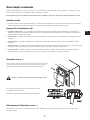
AC Mains
Connect AC power to the IEC socket on the front of the panel by locating the IEC
connector-end of the AC power cord and inserting it fully into the IEC socket on the panel.
Swing the metal retention clip up and over the end of the IEC cable to ensure that the
cable is not inadvertently disconnected.
If the cord supplied by QSC becomes lost or damaged, a replacement 18
gauge IEC power cord may be used.
The DAB-801 does not have a power switch to ensure high reliability.
Caution: Lethal voltages are present in an AC outlet.
AC Mains Disconnection
To remove the AC mains cord, unlatch the metal retention clip and grasp the IEC connector’s plastic body. Pull straight out, removing the connector
from the socket.

6
EN
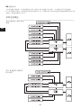
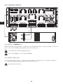
7
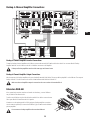
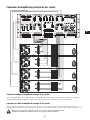
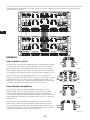
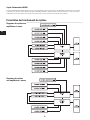
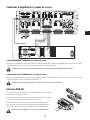
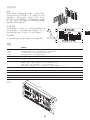
System Diagram with
2-Channel Amplifier
LED POWER Indicator
The blue LED POWER indicator will illuminate when the AC mains power cord is connected properly and the AC mains are functioning properly.
The LED POWER indicator will extinguish when the AC mains power has been removed from the panel. If the POWER indicator does not illuminate
when the IEC cable is connected, verify the AC mains line cord is properly attached to the panel and plugged into the AC outlet. Verify the outlet is
functioning properly.
System Connection Overview
System Diagram with
4-Channel Amplifier

6
7
EN
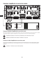
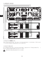
Primary I/O Frame Connections
Q Sys
TM
Frame
DAB-801
I/O Frame DataPort Connections
Connect male to male QSC DataPort cables from the HD-15 connectors on the rear
of the primary I/O Frame to the DAB-801. DataPort connections should be made
from I/O Frame to the upper and outermost HD-15 connections on the DAB-801.
These connections are labeled “Primary Q-Sys DataPorts” and are designated with
letters A-D.
I/O Frame GPIO Connections
Connect a male to male DB-15 cable from the GPIO port on the primary I/O Frame
to the DAB-801 DB-15 connector labeled “Primary Q-Sys GPIO.”

8
EN
9
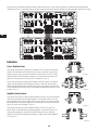
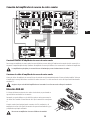
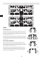
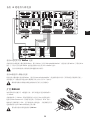
Backup I/O Frame Connections
Backup I/O Frame GPIO Connections
If a backup I/O Frame is used (optional), connect a male to male DB-15 cable from the GPIO port on the backup I/O Frame to the DAB-801 DB-15
connector labeled “Backup Q-Sys GPIO.”
2-channel backup amplifiers must use the DataPort labeled “X“ on the DAB-801. DO NOT USE DATAPORT “Y.“
Q Sys
TM
Frame
DAB-801
Backup I/O Frame DataPort Connections
If a backup I/O Frame is used (optional), connect its HD-15 connectors to the DAB-801 using QSC DataPort cables. Backup DataPort connections
should be made from I/O Frame to the upper and innermost HD-15 connections on the DAB-801. These connections are labeled “Backup Q-Sys
DataPorts” and are designated with letters A-D.
It is important that the connections from the primary and backup I/O Frames are identical. If port A on the primary I/O Frame
connects to primary port A on the DAB-801, then port A on the backup I/O Frame must connect to backup port A on the DAB-801.

8
9
EN
Primary 2-Channel Amplifier Connections
Primary 2-Channel Amplifier Output Connections
Wire the outputs of the primary amplifiers to the green detachable terminal blocks labeled “Connect to Primary Amplifier” on the DAB-801. The
outputs of primary amplifier “A” should connect to the section of detachable terminal block that is labeled “A.”
Make sure that each amplifier output is connected to the correct section of its terminal block.
Each terminal block supports up to 4-channels of amplifier output.
Primary 2-Channel Amplifier DataPort Connections
To attach 2-channel amplifiers to the DAB-801, connect male to male QSC DataPort cables from the HD-15 connectors labeled “Primary Amplifier
DataPorts” on the DAB-801 to the HD-15 DataPort connectors on the amplifiers.

10
EN
11
Backup 2-Channel Amplifier Connections
Backup 2-Channel Amplifier DataPort Connections
To attach a backup 2-channel amplifier to the DAB-801, connect a male to male QSC DataPort cable from the HD-15 connector labeled “Backup
Amplifier DataPorts” on the DAB-801 to the HD-15 DataPort connector on the amplifier.
Primary and backup amplifiers must be of the same type and channel count.
It is mandatory that the backup DataPort labeled “X” on the DAB-801 be used for this.
Backup 2-Channel Amplifier Output Connections
Wire the outputs of the backup amplifier to the green detachable terminal block labeled “Connect to Backup Amplifier” on the DAB-801. The output of
backup amplifier “X” should connect to the section of detachable terminal block that is labeled “X.”
Backup speaker connections “Y“ should be left open.

10
11
EN
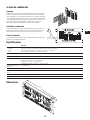
Loudspeaker Connections
To wire the loudspeakers to the DAB-801, connect the facility wiring to the green detachable terminal blocks labeled “Connect to Facility Speakers”
on the DAB-801.
Make sure that each amplifier output is connected to the correct section of its terminal block.

12
EN
13
Primary 4-Channel Amplifier DataPort Connections
To attach a 4-channel amplifier to the DAB-801, connect male to male QSC DataPort cables from the HD-15 connectors labeled “Primary Amplifier
DataPorts” on the DAB-801 to the HD-15 DataPort connectors on the amplifiers.
Primary 4-Channel Amplifier Output Connections
Wire the outputs of the primary amplifiers to the green detachable terminal blocks labeled “Connect to Primary Amplifier” on the DAB-801. The
outputs of primary amplifier “A” should connect to the section of detachable terminal block that is labeled “A.”
Make sure that each amplifier output is connected to the correct section of its terminal block.
Primary 4-Channel Amplifier Connections

12
13
EN
Extension DAB-801
If the system design requires more than 8-channels of redundancy, a second DAB-801
may be added via the extension bus.
To add a second DAB-801 use the included male to male DB-37 cable to connect the two
DB-37 ports labeled “Control Extension Bus” together.
Continue to use the primary panel for GPIO, paging and backup amplifier connections.
Use the extension panel only to connect the additional Q-Sys
TM
DataPorts and additional
primary amplifiers.
Do not connect a backup amplifier to the extension DAB-801!
Backup 4-Channel Amplifier DataPort Connections
To attach a backup 4-channel amplifier to the DAB-801, connect male to male QSC DataPort cables from the HD-15 connector labeled “Backup
Amplifier DataPorts” on the DAB-801 to the HD-15 DataPort connectors on the amplifier.
Primary and backup amplifiers must be of the same type and channel count.
Backup 4-Channel Amplifier Output Connections
Wire the outputs of the backup amplifier to the green detachable terminal block labeled “Connect to Backup Amplifier” on the DAB-801. The output of
backup channels “X” should connect to the section of detachable terminal block that is labeled “X.”
Make sure that each amplifier output is connected to the correct section of its terminal block.
Backup 4-Channel Amplifier Connections

14
EN
15
Instead connect the detachable terminal block labeled “Speaker Extension Bus” on the extension DAB-801 to the detachable terminal block labeled
“Speaker Extension Bus” on the primary DAB-801. All other connections required for extension operation are routed internally through the DB-37 cable.
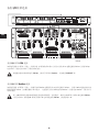
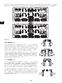
Indicators
Q-Sys
TM
DataPort Status
There are two LEDs above each primary Q-Sys DataPort connector. The green LEDs labeled
“Normal” are illuminated when the primary Q-Sys I/O Frame is active and connected to the
DAB-801 through the GPIO connector. If the primary I/O Frame fails, the red LEDs over the
DataPorts labeled “Fault” will illuminate, indicating an I/O Frame failure. Depending on the
nature of the failure, the green LEDs may or may not extinguish. (Figure 1)
There are two LEDs above each backup Q-Sys DataPort connector. The green LEDs labeled
“Ready” are illuminated when the backup Q-Sys I/O Frame is active and connected to the
DAB-801 through the backup GPIO connector. If the primary I/O Frame fails, the yellow LEDs
over the DataPorts labeled “Backup Active” will illuminate, indicating that the backup I/O Frame
in online. (Figure 2)
Amplifier DataPort Status
There are two LEDs above each primary amplifier DataPort connector. The green LEDs labeled
“Normal” are illuminated when the primary amplifier is connected and active. If one of the
primary amplifiers fails, the red LED labeled “Fault” over the DataPorts connected to the faulty
amp will illuminate, indicating an amplifier failure. Depending on the nature of the failure, the
green LEDs may or may not extinguish. (Figure 3)
There are two LEDs above each backup amplifier DataPort connector. The green LEDs
labeled “Ready” are illuminated when the backup amplifier is connected and active. If one
of the primary amplifiers fails, the yellow LED labeled “Backup Active” over the backup
DataPort connected to the backup amp will illuminate, indicating that the backup amplifier is
in use. (Figure 4)
– Figure 1 –
– Figure 2 –
– Figure 3 –
– Figure 4 –

14
15
EN
DAB-801
Connectors
Input
Output
Other
6 position “Euro” or “Phoenix” type, QSC DataPort (HD-15), QSC GPIO (DB-15).
QSC DataPort (HD-15), 8 position high current “Euro” or “Phoenix” type.
Control Extension Bus (DB-37), IEC type AC Inlet.
Controls Page Assignment: 8 position “dip” type toggle switch.
Page/Alarm Inputs Balanced, 5k ohm, 3 Vrms.
LED Indicators POWER (blue, 1 each).
NORMAL (green, 8 each, 1 per primary DP).
FAULT (red, 8 each, 1 per primary DP).
BACKUP ACTIVE (yellow, 6 each, 1 per backup DP).
Maximum Amplifier Ratings 1200 W per channel
Power Requirements 100 – 240 VAC, 50 – 60 Hz, 12 W max.
Operating Temperature (Tma) 0°C – 40°C non condensing
Dimensions (HWD)
7" (17.8 cm) 4 RU x 19" (48.3 cm) rack mounting x 2" (5.1 cm)
Weight (net/shipping) 7.8 lb (3.5 kg) / 10.8 lb (5 kg)
Paging Section
Connection
The DAB-801 has two non-networked, analog paging inputs. Both of the
page inputs override all Q-Sys
TM
system inputs. The first input, located on a 6
position detachable header, is labeled “Page Input.” The second input, also
located on a 6 position detachable header, is labeled “Alarm Input.” An 8
position routing switch selects which amplifier channels receive the page or
alarm signal.
Page Priority
The “Page Input,” when enabled, will override all Q-Sys system inputs on the
selected channels. The “Alarm Input,” when enabled, will override both the
Page Inputs as well as the Q-Sys system inputs.
Extension Panel
Each panel must have its own Page/Alarm signals connected, and routing
switches set.
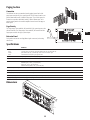
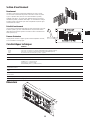
Dimensions
Specifications
19"
48.3 cm
2"
5.1 cm
7"
17.8 cm

Mailing Address:
QSC Audio Products, LLC
1675 MacArthur Boulevard
Costa Mesa, CA 92626-1468 USA
Telephone Numbers:
Main Number: (714) 754-6175
Sales & Marketing: (714) 957-7100 or toll free (USA only) (800) 854-4079
Customer Service: (714) 957-7150 or toll free (USA only) (800) 772-2834
Facsimile Numbers:
Sales & Marketing FAX: (714) 754-6174
Customer Service FAX: (714) 754-6173
World Wide Web:
www.qscaudio.com
E-mail:
© 2009 QSC Audio Products, LLC. All rights reserved. QSC, the QSC logo and Q-Sys are registered trademarks of QSC Audio Products, LLC in the U.S. Patent and Trademark office and other countries.
All other trademarks are the property of their respective owners. Patents may apply or be pending.

Manual de instalación del hardware
DAB-801 – Reserva del amplificador DataPort, 8-canales
Amplificador y accesorio de reserva del bastidor E/S para el sistema Q-Sys
TM
*TD-000292-00*
TD-000292-00-A
DAB-801

2
SP
3
PRECAUCIONES DE SEGURIDAD IMPORTANTES Y EXPLICACIÓN DE LOS SÍMBOLOS
¡ADVERTENCIA!
Todos los productos fabricados por QSC Audio Products, LLC están diseñados para su operación segura, y agencias reconocidas de seguridad de los
productos certifican que cumplen con todos los estándares normales para este tipo de producto. Sin embargo, dentro del panel del relé de este amplificador
DataPort existen voltajes y niveles de energía peligrosos. Se pide al usuario leer las precauciones en este manual. Si el producto se ha caído, abollado, mojado
o parece tener piezas sueltas en su interior, se aumentará el riesgo de sufrir descargas eléctricas. Desconecte el cable de CA y lleve el producto al personal de
servicio calificado para su inspección y reparación. Consulte a un ingeniero profesional con la debida licencia con respecto a la instalación del equipo físico.
Asegúrese de comprender y acatar todas las normas locales, estatales y nacionales referentes a la seguridad y operación de equipos suspendidos.
ASISTENCIA Y SERVICIO TÉCNICO
QSC Audio Products, LLC mantiene una red internacional de distribuidores y centros de servicio. Estas agencias locales podrán responder sus preguntas y
solucionar cualquier problema.
Lea estas instrucciones.1.
Conserve estas instrucciones.2.
Ponga atención a todas las advertencias3.
Siga todas las instrucciones4.
ADVERTENCIA: Para prevenir incendios o descargas eléctricas, no exponga este equipo a la lluvia ni a la humedad. No use este aparato cerca del agua.5.
Límpielo sólo con un paño seco.6.
No obstruya ninguna abertura de ventilación. Instale el equipo de acuerdo con las instrucciones del fabricante.7.
No lo instale cerca de fuentes de calor tales como radiadores, registros térmicos, estufas ni otros aparatos que produzcan calor.8.
El acoplador del equipo es la desconexión de la línea principal de CA y debe permanecer fácilmente operable después de la instalación.9.
No anule la característica de seguridad del enchufe con conexión a tierra. Un enchufe con conexión a tierra tiene dos hojas y un terminal de conexión a 10.
tierra. La hoja ancha o el tercer terminal se proporcionan para su seguridad. Si el enchufe que se le proporciona no cabe en su tomacorriente, consulte
con un electricista para reemplazar el tomacorriente obsoleto. Este aparato debe estar conectado a un receptáculo con conexión a tierra.
Proteja el cable de alimentación para que no lo pisen ni se le comprima, particularmente en los enchufes, los receptáculos y el punto en donde éstos 11.
salen del aparato.
Use sólo piezas/accesorios especificados por QSC Audio Products, LLC.12.
Use sólo el herraje, los soportes, las bases y componentes vendidos con el aparato o por QSC Audio Products,LLC.13.
Desconecte el aparato durante tormentas eléctricas o cuando no lo vaya a usar durante periodos prolongados.14.
Refiera todo el servicio a personal calificado. Es necesario dar servicio al aparato cuando sufra algún daño, como cuando se daña el cable de 15.
alimentación eléctrica o el enchufe, cuando se derraman líquidos o caen objetos sobre el aparato, cuando éste ha estado expuesto a la lluvia o humedad,
cuando no opere normalmente o cuando se haya caído.
El símbolo de un rayo con punta de flecha dentro de un triángulo equilátero tiene el propósito de alertar al usuario de la presencia de voltaje
“peligroso” no aislado dentro de la caja del producto, que puede ser de suficiente magnitud para constituir un riesgo de descarga eléctrica a
los seres humanos.
El signo de exclamación dentro de un triángulo equilátero tiene la intención de alertar al usuario de la presencia de instrucciones importantes de
operación y mantenimiento (servicio) en este manual.
PRECAUCIÓN: PARA REDUCIR EL RIESGO DE DESCARGAS ELÉCTRICAS, NO QUITE LA CUBIERTA. EL INTERIOR NO CONTIENE
PIEZAS A LAS QUE EL USUARIO PUEDA DAR SERVICIO. REFIERA EL SERVICIO A PERSONAL CALIFICADO.

2
3
SP
Garantía (sólo para EE.UU.; para otros países, consulte con su vendedor o
distribuidor)
Cláusula de exención de responsabilidad
QSC Audio Products, LLC no es responsable por ningún daño a este panel del relé ni a ningún otro equipo, que sea causado por negligencia o instalación
y/o uso inadecuado de este producto.
Garantía limitada de 3 años de QSC Audio Products
QSC Audio Products, LLC (“QSC”) garantiza que sus productos estarán libres de materiales y/o mano de obra defectuosos y reemplazará las piezas defectuosas y
reparará los productos que funcionen mal bajo esta garantía cuando el defecto ocurra bajo condiciones normales de instalación y uso, siempre y cuando la unidad
se devuelva a nuestra fábrica, a una de nuestras estaciones autorizadas de servicio o a un distribuidor autorizado de QSC International mediante transportación
prepagada con una copia del comprobante de compra (por ejemplo, el recibo de la compra). Esta garantía requiere que la inspección del producto devuelto indique,
en nuestra opinión, un defecto de fabricación. Esta garantía no se extiende a ningún producto que haya estado sometido a uso indebido, negligencia, accidente,
instalación incorrecta, o que se haya quitado o modificado el código de la fecha. QSC tampoco será responsable por daños incidentales y/o emergentes. Esta garantía
le otorga derechos legales específicos. Esta garantía limitada es transferible durante el período de la misma. La garantía de los productos QSC NO ES VÁLIDA si los
productos se compraron de un distribuidor no autorizado o de un comerciante en línea, o si el número de serie original de fábrica se quita, altera o reemplaza de
alguna manera. El daño o pérdida de cualquier software o datos que residan en el producto no está cubierto por la garantía. Al proporcionar servicio de reparación o
reemplazo, QSC hará todos los esfuerzos razonables para reinstalar la configuración original del software del producto y las versiones de actualización subsiguientes,
pero no ofrece la recuperación ni la transferencia del software o de los datos contenidos en la unidad a la que se dio servicio que no estaban incluidos originalmente
en el producto.
Los clientes podrían tener derechos adicionales, que varían de un estado a otro o de un país a otro.
Esta garantía se actualiza periódicamente. Para obtener la versión más reciente de la declaración de garantía de QSC, visite www.qscaudio.com.
Comuníquese con nosotros al teléfono 800-854-4079 o visite nuestro sitio en Internet en www.qscaudio.com.
La garantía limitada de QSC es válida por un periodo de tres (3) años a partir de la fecha de compra en Estados Unidos y en muchos otros países
(pero no en todos).
Si desea información sobre la garantía de QSC en países que no sean Estados Unidos, comuníquese con su distribuidor internacional de QSC autorizado. Puede encontrar
una lista de los distribuidores internacionales de QSC en www.qscaudio.com.
Para registrar su producto QSC en línea, visite www.qscaudio.com y seleccione ”Product Registration” (Registro del producto). Puede recibir respuesta a otras preguntas
referentes a esta garantía llamando, enviando un mensaje electrónico o comunicándose con su distribuidor QSC autorizado.
© 2009, QSC Audio Products, LLC.
Pueden aplicar patentes o estar en trámite.
QSC es una marca comercial registrada de QSC Audio Products, LLC.
“QSC” y el logotipo de QSC están registrados con la Oficina de Patentes y Marcas Comerciales de los EE.UU..
Todas las marcas comerciales son propiedad de sus respectivos dueños.

4
SP
5
Introducción
Muchas gracias por haber comprado el sistema de reserva DAB-801 del amplificador Q-Sys
TM
. A fin de asegurar la operación correcta en el caso poco probable de una
falla del amplificador o del sistema Q-Sys, recomendamos que lea toda la información que se proporciona en este manual de instalación.
El DAB-801 extiende la capacidad de reserva del Q-Sys para incluir amplificadores de potencia QSC designados y bastidores E/S con tarjetas CODP4. El DAB-801 añade
la capacidad de agregar redundancia N+1 de amplificador a cualquier sistema para hasta 8 canales, así como la capacidad de cambiar automáticamente todos los
amplificadores conectados a DataPort de un bastidor E/S principal a un bastidor E/S de reserva.
El DAB-801 se integra fácilmente a un sistema de audio basado en Q-Sys. Montado en la parte posterior del bastidor, el DAB-801 minimiza el consumo de espacio en
el bastidor. La conexión a la línea de CA es rápida y fácil; un desacoplador rápido estilo IEC con soporte de bloqueo asegura una conexión confiable a la línea eléctrica
de CA. Suministro eléctrico internacional, opera con 100-240 VCA, 50-60 Hz. Con el uso de conectores DataPort HD-15 estándar de QSC y bloques de terminales de
alta corriente desmontables, el DAB-801 proporciona un juego de conectores fácil de instalar. Dos conexiones D-Sub de 15 pines permiten la conexión directa a un par
de bastidores E/S para el control y la supervisión del DAB-801. Dos modalidades de señalización están disponibles para la señalización de alta prioridad, y se activan ya
sea con un cierre de contacto estándar o con un voltaje activador de +12 VCC. Se pueden combinar dos paneles DAB-801 usando el cable de 37 pines que se incluye
para obtener un total de 16 canales de bastidor E/S y redundancia N+1.
Varios indicadores LED alertan al usuario del estado actual del panel. Los LED incluyen un indicador de potencia CA, indicadores de estado de potencia del bastidor
E/S, indicadores de estado de potencia del amplificador, indicadores de falla del bastidor E/S e indicadores de falla del amplificador.
Descargue la última versión del software Q-Sys para asegurarse de que su sistema funcione con este accesorio.
Glosario
Línea eléctrica de CA – El voltaje de CA presente en un receptáculo o tomacorriente de pared.
Reserva – El artículo de redundancia en un sistema a prueba de fallas. Si el artículo principal falla, el artículo de reserva reemplaza al principal, restableciendo el
funcionamiento total del sistema.
CODP4 – Tarjeta de salida QSC diseñada para montarse internamente en un bastidor E/S. Se conecta a dos amplificadores con DataPort o a un
amplificador sencillo de cuatro canales.
D-Sub (o DB) – Un tipo de conector de cableado cuya cubierta externa tiene la forma de una letra D mayúscula. Los conectores tipo DB tienen dos filas
individuales de pines.
DataPort – Una conexión patentada de QSC que acompaña a muchos de nuestros amplificadores de instalación y para giras. Usa un conector tipo HD-15.
Panel de extensión – Un DAB-801 idéntico que está conectado a un DAB-801 maestro, aumentando la capacidad de canales total del sistema a hasta
16 canales de audio.
Tolerante a -las fallas – Un sistema que continúa funcionando, posiblemente a niveles reducidos pero sin fallar completamente, cuando alguna parte del sistema
falla.
GPIO – Abreviatura que significa General Purpose Input and Output. (entrada y salida de uso general).
HD15 – Un tipo de conector de cableado de alta densidad cuya cubierta externa tiene la forma de una letra D mayúscula. Los conectores tipo HD tienen tres filas
individuales de pines. El número “15” indica el número total de pines en el conector.
Receptáculo IEC – Un tipo estándar de conector de línea eléctrica de CA que se utiliza en la mayoría de equipos para el consumidor.
Bastidor E/S – Hardware de QSC que se usa para la entrada y la salida de señales de audio de un sistema Q-Sys.
Redundancia N+1 – Un sistema que tiene “N” artículos y un solo sistema de reserva. Si algún artículo sencillo falla, el sistema reemplaza automáticamente ese
artículo con la reserva. En el caso del DAB-801, los amplificadores son redundantes de esta manera.
Bastidor E/S principal – El bastidor E/S principal en el sistema resistente a las fallas. Si el bastidor E/S principal falla, el artículo de reserva automáticamente restablece
el funcionamiento total del sistema.
Q-Sys
TM
– Un sistema patentado de QSC Audio.
La page est en cours de chargement...
La page est en cours de chargement...
La page est en cours de chargement...
La page est en cours de chargement...
La page est en cours de chargement...
La page est en cours de chargement...
La page est en cours de chargement...
La page est en cours de chargement...
La page est en cours de chargement...
La page est en cours de chargement...
La page est en cours de chargement...
La page est en cours de chargement...
La page est en cours de chargement...
La page est en cours de chargement...
La page est en cours de chargement...
La page est en cours de chargement...
La page est en cours de chargement...
La page est en cours de chargement...
La page est en cours de chargement...
La page est en cours de chargement...
La page est en cours de chargement...
La page est en cours de chargement...
La page est en cours de chargement...
La page est en cours de chargement...
La page est en cours de chargement...
La page est en cours de chargement...
La page est en cours de chargement...
La page est en cours de chargement...
La page est en cours de chargement...
La page est en cours de chargement...
La page est en cours de chargement...
La page est en cours de chargement...
La page est en cours de chargement...
La page est en cours de chargement...
La page est en cours de chargement...
La page est en cours de chargement...
La page est en cours de chargement...
La page est en cours de chargement...
La page est en cours de chargement...
La page est en cours de chargement...
La page est en cours de chargement...
La page est en cours de chargement...
La page est en cours de chargement...
La page est en cours de chargement...
La page est en cours de chargement...
La page est en cours de chargement...
La page est en cours de chargement...
La page est en cours de chargement...
La page est en cours de chargement...
La page est en cours de chargement...
La page est en cours de chargement...
La page est en cours de chargement...
La page est en cours de chargement...
La page est en cours de chargement...
La page est en cours de chargement...
La page est en cours de chargement...
La page est en cours de chargement...
La page est en cours de chargement...
La page est en cours de chargement...
La page est en cours de chargement...
-
 1
1
-
 2
2
-
 3
3
-
 4
4
-
 5
5
-
 6
6
-
 7
7
-
 8
8
-
 9
9
-
 10
10
-
 11
11
-
 12
12
-
 13
13
-
 14
14
-
 15
15
-
 16
16
-
 17
17
-
 18
18
-
 19
19
-
 20
20
-
 21
21
-
 22
22
-
 23
23
-
 24
24
-
 25
25
-
 26
26
-
 27
27
-
 28
28
-
 29
29
-
 30
30
-
 31
31
-
 32
32
-
 33
33
-
 34
34
-
 35
35
-
 36
36
-
 37
37
-
 38
38
-
 39
39
-
 40
40
-
 41
41
-
 42
42
-
 43
43
-
 44
44
-
 45
45
-
 46
46
-
 47
47
-
 48
48
-
 49
49
-
 50
50
-
 51
51
-
 52
52
-
 53
53
-
 54
54
-
 55
55
-
 56
56
-
 57
57
-
 58
58
-
 59
59
-
 60
60
-
 61
61
-
 62
62
-
 63
63
-
 64
64
-
 65
65
-
 66
66
-
 67
67
-
 68
68
-
 69
69
-
 70
70
-
 71
71
-
 72
72
-
 73
73
-
 74
74
-
 75
75
-
 76
76
-
 77
77
-
 78
78
-
 79
79
-
 80
80


QSC DAB-801 Manuel utilisateur
- Catégorie
- Matériel musical
- Taper
- Manuel utilisateur
dans d''autres langues
- English: QSC DAB-801 User manual
- español: QSC DAB-801 Manual de usuario
- Deutsch: QSC DAB-801 Benutzerhandbuch
Documents connexes
-
QSC PS-X Manuel utilisateur
-
QSC CX1102 Manuel utilisateur
-
QSC CX108V Manuel utilisateur
-
-
QSC CX 502 Manuel utilisateur
-
-
QSC DCA 3422 Manuel utilisateur
-
QSC PL340 Manuel utilisateur