
CURV 500
®
I AMP
4 CHANNEL CLASS D INSTALLATION AMPLIFIER
LDCURV500IAMP
USER´S MANUAL
BEDIENUNGSANLEITUNG
MANUEL D`UTILISATION
MANUAL DE USUARIO
INSTRUKCJA OBSŁUGI
MANUALE D‘ USO
操作说明书
操作說明書

CONTENTS / INHALTSVERZEICHNIS / CONTENU / CONTENIDO / TREŚĆ / CONTENUTO /
目录 / 目錄
ENGLISH
PREVENTIVE MEASURES 3-4
INTRODUCTION 4
CONNECTIONS, OPERATING AND DISPLAY ELEMENTS 5
OPERATION 6-10
BRIDGE MODE / 70 V OPERATION 10-11
CONFIGURATION OF SPEAKER OUTPUTS 11
TECHNICAL DATA 12
MANUFACTURER’S DECLARATIONS 13
DEUTSCH
SICHERHEITSHINWEISE 14-15
EINFÜHRUNG 15
ANSCHLÜSSE, BEDIEN- UND ANZEIGEELEMENTE 16
BEDIENUNG 17-22
BRIDGE-MODUS / 70 V-BETRIEB 22-23
BELEGUNG LAUTSPRECHERAUSGÄNGE 23
TECHNISCHE DATEN 24
HERSTELLERERKLÄRUNGEN 25
FRANCAIS
MESURES PRÉVENTIVES 26-27
INTRODUCTION 27
RACCORDEMENTS, ÉLÉMENTS DE COMMANDE ET D’AFFICHAGE
28
MODE D’EMPLOI 29-33
MODO BRIDGE / FUNCIONAMIENTO 70 V 34-35
AFFECTATION DES SORTIES DE HAUT-PARLEUR 35
CARACTÉRISTIQUES TECHNIQUES 35-36
DECLARATIONS 36
ESPAÑOL
MEDIDAS DE SEGURIDAD 37-38
INTRODUCCIÓN 38
CONEXIONES, ELEMENTOS DE MANEJO E INDICACIÓN 39-40
FUNCIONAMIENTO 40-44
MODO BRIDGE / FUNCIONAMIENTO A 70 V 44-45
ASIGNACIÓN DE SALIDAS DE ALTAVOZ 46
DATOS TÉCNICOS 46-47
DECLARACIONES DEL FABRICANTE 47
POLSKI
ŚRODKI OSTROŻNOŚCI 48-49
WPROWADZENIE 49
GNIAZDA, PANEL OBSŁUGI I WSKAŹNIKI 50
OBSŁUGA 51-55
TRYB MOSTU/ ZASILANIA 70 V 55-56
ZAJMOWANIE WYJŚĆ GŁOŚNIKOWYCH 57
DANE TECHNICZNE 57-58
DEKLARACJE PRODUCENTA 58
ITALIANO
MISURE PRECAUZIONALI 59-60
INTRODUZIONE 60
RACCORDI, ELEMENTI DI COMANDO E DI VISUALIZZAZIONE 61
COMANDO 62-66
BRIDGE MODE/70V 66-67
DISPOSIZIONE USCITE ALTOPARLANTE 68
DATI TECNICI 68-69
DICHIARAZIONI DEL PRODUTTORE 69
简体中文
安全须知 70-71
引言 71
接口、操作和显示元件 72
操作 73-77
橋接模式/70V設備 77-78
揚聲器輸出配置 78
技术参数 79
制造商声明 80
繁體中文
安全注意事項 81-82
引言 82
連接、操作及顯示元件 83
操作 84-88
桥接模式/70V运行模式 88-89
扬声器输出分配 90
技術規格 90-91
製造商聲明 91

3
DEUTSCH
ENGLISHFRANCAIS
ESPAÑOL
POLSKIITALIANO
简体中文繁體中文
ENGLISH
YOU‘VE MADE THE RIGHT CHOICE!
We have designed this product to operate reliably over many years. LD Systems stands for this with its name and many years of experience
as a manufacturer of high-quality audio products. Please read this User‘s Manual carefully, so that you can begin making optimum use of
your LD Systems product quickly.
You can nd more information about LD-SYSTEMS at our Internet site WWW.LD-SYSTEMS.COM
SAFETY INFORMATION
1. Please read these instructions carefully.
2. Keep all information and instructions in a safe place.
3. Follow the instructions.
4. Observe all safety warnings. Never remove safety warnings or other information from the equipment.
5. Use the equipment only in the intended manner and for the intended purpose.
6. Use only sufciently stable and compatible stands and/or mounts (for xed installations). Make certain that wall mounts are properly
installed and secured. Make certain that the equipment is installed securely and cannot fall down.
7. During installation, observ e the applicable safety regulations for your country.
8. Never install and operate the equipment near radiators, heat registers, ovens or other sources of heat. Make certain that the equipment
is always installed so that is cooled sufciently and cannot overheat.
9. Never place sources of ignition, e.g., burning candles, on the equipment.
10. Ventilation slits must not be blocked.
11. Keep a minimum distance of 20 cm around and above the device.
12. Do not use this equipment in the immediate vicinity of water (does not apply to special outdoor equipment - in this case, observe the
special instructions noted below. Do not expose this equipment to ammable materials, uids or gases. Avoid direct sunlight!
13. Make certain that dripping or splashed water cannot enter the equipment. Do not place containers lled with liquids, such as vases or
drinking vessels, on the equipment.
14. Make certain that objects cannot fall into the device.
15. Use this equipment only with the accessories recommended and intended by the manufacturer.
16. Do not open or modify this equipment.
17. After connecting the equipment, check all cables in order to prevent damage or accidents, e.g., due to tripping hazards.
18. During transport, make certain that the equipment cannot fall down and possibly cause property damage and personal injuries.
19. If your equipment is no longer functioning properly, if uids or objects have gotten inside the equipment or if it has been damaged in
anot her way, switch it off immediately and unplug it from the mains outlet (if it is a powered device). This equipment may only be repaired
by authorized, qualied personnel.
20. Clean the equipment using a dry cloth.
21. Comply with all applicable disposal laws in your country. During disposal of packaging, please separate plastic and paper/cardboard.
22. Plastic bags must be kept out of reach of children.
23. Please note that changes or modications not expressly approved by the party responsible for compliance could void the user´s
authority to operate the equipment.
FOR EQUIPMENT THAT CONNECTS TO THE POWER MAINS
24. CAUTION: If the power cord of the device is equipped with an earthing contact, then it must be connected to an outlet with a protective
ground. Never deactivate the protective ground of a power cord.
25. If the equipment has been exposed to strong uctuations in temperature (for example, after transport), do not switch it on immediately.
Moisture and condensation could damage the equipment. Do not switch on the equipment until it has reached room temperature.
26. Before connecting the equipment to the power outlet, rst verify that the mains voltage and frequency match the values specied on
the equipment. If the equipment has a voltage selection switch, connect the equipment to the power outlet only if the equipment values
and the mains power values match. If the included power cord or power adapter does not t in your wall outlet, contact your electrician.
27. Do not step on the power cord. Make certain that the power cable does not become kinked, especially at the mains outlet and/or power
adapter and the equipment connector.
28. When connecting the equipment, make certain that the power cord or power adapter is always freely accessible. Always disconnect the
equipment from the power supply if the equipment is not in use or if you want to clean the equipment. Always unplug the power cord and
power adapter from the power outlet at the plug or adapter and not by pulling on the cord. Never touch the power cord and power adapter
with wet hands.
29. Whenever possible, avoid switching the equipment on and off in quick succession because otherwise this can shorten the useful life of
the equipment.
30. IMPORTANT INFORMATION: Replace fuses only with fuses of the same type and rating. If a fuse blows repeatedly, please contact an
authorised service centre.
31. To disconnect the equipment from the power mains completely, unplug the power cord or power adapter from the power outlet.
32. If your device is equipped with a Volex power connector, the mating Volex equipment connector must be unlocked before it can be

4
DEUTSCHENGLISH FRANCAIS
ESPAÑOL
POLSKI ITALIANO
简体中文 繁體中文
removed. However, this also means that the equipment can slide and fall down if the power cable is pulled, which can lead to personal
injuries and/or other damage. For this reason, always be careful when laying cables.
33. Unplug the power cord and power adapter from the power outlet if there is a risk of a lightning strike or before extended periods of disuse.
34. The appliance is not to be used by persons (including children) with reduced physical, sensory or mental capabilities, or lack of experience
and knowledge.
35. Children must be instructed not to play with the device.
36. If the power cord of the device is damaged, do not use the device. The power cord must be replaced by an adequate cable or assembly from an
authorized service center.
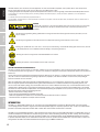
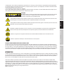
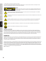
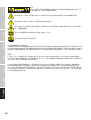
CAUTION:
To reduce the risk of electric shock, do not remove cover (or back). There are no user serviceable
parts inside. Maintenance and repairs should be exclusively carried out by qualied service
personnel.
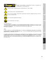
The warning triangle with lightning symbol indicates dangerous uninsulated voltage inside the unit, which may cause an
electrical shock.
The warning triangle with exclamation mark indicates important operating and maintenance instructions.
Warning! This symbol indicates a hot surface. Certain parts of the housing can become hot during operation. After use, wait for
a cool-down period of at least 10 minutes before handling or transporting the device.
Warning! This device is designed for use below 2000 metres in altitude.
Warning! This product is not intended for use in tropical climates.
CAUTION! HIGH VOLUMES IN AUDIO PRODUCTS!
This device is meant for professional use. Therefore, commercial use of this equipment is subject to the respectively applicable national
accident prevention rules and regulations. As a manufacturer, Adam Hall is obligated to notify you formally about the existence of potential
health risks.
Hearing damage due to high volume and prolonged exposure: When in use, this product is capable of producing high sound-pressure levels
(SPL) that can lead to irreversible hearing damage in performers, employees, and audience members. For this reason, avoid prolonged
exposure to volumes in excess of 90 dB.
NOTE: This equipment has been tested and found to comply with the limits for a Class B digital device, pursuant to Part 15 of the FCC Rules. These
limits are designed to provide reasonable protection against harmful interference in a residential installation. This equipment generates, uses
and can radiate radio frequency energy and, if not installed and used in accordance with the instructions, may cause harmful interference to radio
communications. However, there is no guarantee that interference will not occur in a particular installation. If this equipment does cause harmful
interference to radio or television reception, which can be determined by turning the equipment off and on, the user is encouraged to try to correct
the interference by one or more of the following measures:
- Reorient or relocate the receiving antenna.
- Increase the separation between the equipment and receiver.
- Connect the equipment into an outlet on a circuit different from that to which the receiver is connected.
- Consult the dealer or an experienced radio/TV technician for help.
INTRODUCTION
The I AMP is a 4-channel power amplier in a 19" rack format, specically developed for installations of CURV-500-Systems. The at design with
class-D topology and DSP control has a highly efcient switch mode power supply and a frequency response of 10 Hz - 22 kHz. Each channel features
parametric EQ and delay and provides 240 watts RMS at 4 ohms with a total harmonic distortion of less than 0.01 %.
The I AMP is easily and intuitively operated via a push-and-turn dial and a high-contrast, easily readable OLED display. It is equipped with a soft start
and low-noise temperature-controlled fans and protected against direct current, overloading, overheating and short-circuiting. The balanced inputs
are XLR sockets and terminal block connections. The I AMP can power up to six CURV-500 satellites or one CURV500ISUB subwoofer per channel via
its Speakon-compatible output jacks or terminal block connections. Presets for speakers from the CURV500 series are pre-installed. PC software for
management of the I AMP is available to download from the product page at WWW.LD-SYSTEMS.COM.

5
DEUTSCH
ENGLISHFRANCAIS
ESPAÑOL
POLSKIITALIANO
简体中文繁體中文
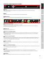
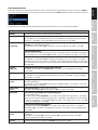
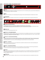
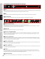
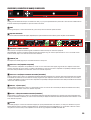
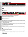
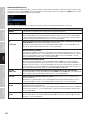
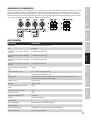
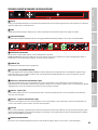
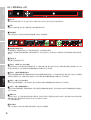
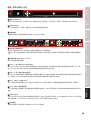
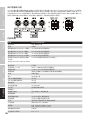
CONNECTIONS, OPERATING AND DISPLAY ELEMENTS
1
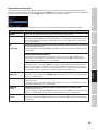
DISPLAY
Multi-functional OLED graphics display for information such as preset and audio signal level. It also shows menu items to view
system settings as required.
2
MENU
Combined push-and-turn dial to access the edit menu and select and edit individual menu items.
3
VENTILATION GRILL
In order to avoid overheating of the device, ensure that the ventilation grill is not covered and that air can circulate freely.
4
POWER SOCKET AND FUSE HOLDER
IEC mains socket with built-in fuse holder. A suitable power cable is included.
IMPORTANT: Replace the fuse only with a fuse of the same type. Follow the instructions printed on the housing. In the event of repeated fuse
failure, please contact an authorised service centre.
5
POWER ON / OFF
On / Off switch for power supply to the device.
6
OUTPUT CH A - CH D (speakON-compatible)
SpeakON-compatible loudspeaker outputs for channels A to D. To avoid damage to the equipment, make sure that the total impedance of the
connected speakers is at least 2.7 ohms per channel. The speakON-compatible connectors and the screw connections of each corresponding
channel are wired in parallel.
7
OUTPUT CH A - CH D (screw connection)
Loudspeaker outputs for channels A to D with terminal block connections (screw connectors supplied). To avoid damage to the equipment, make
sure that the total impedance of the connected speakers is at least 2.7 ohms per channel. The speakON-compatible connectors and the screw
connections of each corresponding channel are wired in parallel.
8
INPUTS 1 - 4 (3-pin XLR)
Balanced line inputs for channels 1 to 4 with 3-pin XLR sockets. The XLR sockets and the terminal block connections of each corresponding channel
are wired in parallel.
9
INPUTS 1 - 4 (terminal block connections)
Balanced line inputs for channels 1 to 4 with terminal block connections (connectors supplied). The XLR sockets and the terminal block connections
of each corresponding channel are wired in parallel.
10
DATA USB
USB interface (Type B) for updating device rmware and loudspeaker presets, managing global presets and resetting the lock PIN.
The corresponding Windows PC programme and current update les can be found along with a manual in the download area of the product
at WWW.LD-SYSTEMS.COM
11
HOUSING FAN
In order to avoid overheating of the device, ensure that the fan is not covered and that air can circulate freely.
4 5
6 7 8
9
11
10
11
1 32

6
DEUTSCHENGLISH FRANCAIS
ESPAÑOL
POLSKI ITALIANO
简体中文 繁體中文
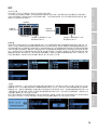
OPERATION
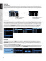
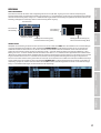
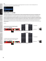
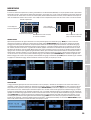
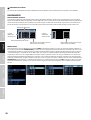
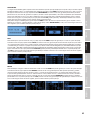
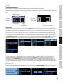
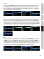
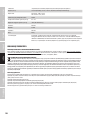
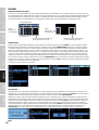
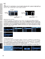
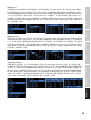
DISPLAY MAIN DISPLAY
After switching on the power amplier, the greeting ”Welcome” is displayed briey. The main display then appears with the following information:
amplier name (editable), amplier channel (CH A - D) with links, speaker preset, audio level with peak indicator and channel mute. Following about
10 minutes of no input, sections of the display fade out and only amplier channel with links, audio level meter with peak display and channel mute
are displayed.
Amplier name
Amplier channel
with links
Speaker preset
Audio level with peak indicator (PK)
and channel mute (mute)
Amplier channel
with links
Audio level with peak indicator (PK)
and channel mute (mute)
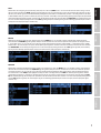
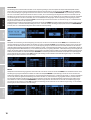
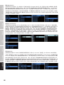
CHANNEL VOLUME
Menu item for setting channel volume. Press the rotary MENUdial to access the selection menu for device settings, and turn the dial to select the
menu item CHANNEL VOLUME (bright background). Now press the dial and select the channel on which you want to adjust the volume by turning
the dial. Press the dial again and then turn it to set the desired volume (anticlockwise = reduce volume, anticlockwise past -60 dB, = mute, clockwise
= increase volume). Press and hold the dial for about 2 seconds to mute or unmute the selected channel (MUTE). To restore the volume of a muted
channel to its previous unmuted level, turn the dial clockwise to increase the volume level slowly and then press for about 2 seconds. Conrm your
entry by pressing the dial. Repeat this procedure to set the desired volume level for the other channels. To return to the selection menu, turn the
dial to select the menu item CH VOLUME EXIT and conrm by pressing the dial. Access the main display by turning the dial to select EXIT (light
background) and conrm by pressing the dial. Following approximately 10 seconds of no input, the main display will appear automatically.
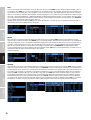
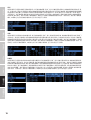
MASTER VOLUME
The overall volume can be set directly from the main display if this option has been activated in the appropriate menu item, and even if the
controls have been locked. Press the rotary MENUdial to access the selection menu for device settings and turn the dial to select the menu item
MASTER VOLUME (bright background). Press the dial twice then turn it to the left to select “ON” and conrm the entry by pressing the dial (if the
option to set overall volume is not available, select “OFF”). Turn the dial to select the arrow symbol and conrm by pressing the dial to return to the
selection menu. To return to the main display, turn the dial to select the menu item EXIT and conrm by pressing the dial. Following approximately
10 seconds of no input, the main display will appear automatically.
Now you can adjust the overall volume level by turning the MENU dial in the desired direction, without having to press it beforehand (anticlockwise
= reduce volume, clockwise = increase volume). The display then changes to MASTER VOLUME (0 to 100). Following approximately 2 seconds of no
input, the main display will appear automatically.

7
DEUTSCH
ENGLISHFRANCAIS
ESPAÑOL
POLSKIITALIANO
简体中文繁體中文
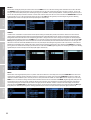
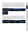
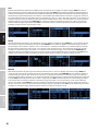
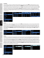
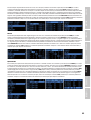
DELAY
Menu item for the conguring the channel delay (delay line). Press the rotary MENUdial to access the selection menu for device settings and turn
the dial to select the menu item DELAY (bright background). Now press the dial, and then turn it to select the channel on which you want to adjust
the delay. Press the dial again and set the desired value by turning the dial (anticlockwise = maximum delay, clockwise = ne tuning from 0 ms). The delay
is shown in milliseconds (ms), as well as in metres (m) or feet (ft) (see SETUP -> DELAY UNIT). Conrm your entry by pressing the dial. Repeat this procedure to
set the desired delay for the other channels. To return to the selection menu, turn the dial to select the menu item DELAY EXIT and conrm by pressing the
dial. Access the main display by turning the dial to select EXIT (light background) and conrm by pressing the dial. Following approximately 10 seconds of
no input, the main display will appear automatically.
ROUTING
Menu item for setting the input source for channels A to D. Press the MENUdial to access the device settings selection menu and turn the dial to
select the menu item ROUTING (light background). Now press the dial and then turn it to select the input source that you want to congure (Channel
A - D, each input source 1 - 4). Press the dial again, select the desired setting by rotating the dial (framed number = activated input source, number
without frame = deactivated input source) and conrm input by pressing the dial. To return to the selection menu, turn the dial to select the menu
item ROUTING EXIT and conrm by pressing the dial. Access the main display by turning the dial to select EXIT (light background) and conrm by
pressing the dial. Following approximately 10 seconds of no input, the main display will appear automatically.
EQUALIZER
Menu item for conguring the 10-band parametric equaliser for channels A to D. Press the MENUdial to access the device settings selection menu,
then turn the dial to select the menu item EQUALIZER (light background). Now press the dial and then turn it to select the channel that you want
to congure (channel A - D). Press the dial again, select the desired equalisation band 01 to 10 by rotating the dial, then conrm by pressing the
dial. Turn the dial to select FREQ (Frequency), Q (lter quality, low shelf LS and high Shelf HS) and GAIN and conrm by pressing the dial. Edit the
corresponding parameters as required and conrm by pressing the dial. To return to channel selection, turn the dial to select the menu item EXIT
EQ and conrm by pressing the dial. Repeat this procedure to set the desired EQ for the other channels. Access the main display by turning the dial
to select EXIT (light background) and conrm by pressing the dial. Following approximately 10 seconds of no input, the main display will appear
automatically.

8
DEUTSCHENGLISH FRANCAIS
ESPAÑOL
POLSKI ITALIANO
简体中文 繁體中文
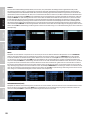
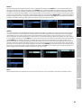
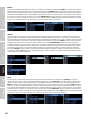
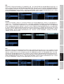
POLARITY
Menu item for setting the polarity of channels A to D. Press the MENUdial to access the device settings menu and then turn it to select the menu
item POLARITY (light background). Now press the dial and then turn it to select the channel that you want to congure (channel A - D). Press the
dial again, select the required polarity and conrm by pressing the dial (NORMAL = normal polarity, INVERTED = inverted polarity). Repeat this proce-
dure to select the polarity for the other channels. To return to the selection menu, turn the dial to select the menu item POLARITY EXIT and conrm
by pressing the dial. Access the main display by turning the dial to select EXIT (light background) and conrm by pressing the dial. Following
approximately 10 seconds of no input, the main display will appear automatically.
LINK SETT
Channels A to D can be linked as required in order to have parallel settings for volume, delay and EQ on the selected channels. This means that the
settings on one of the linked channels will be transferred simultaneously to the other linked channels. Settings that have been congured prior to
linking will be retained until the value of the corresponding parameter is changed. This means that if settings are changed for one channel, they will
be transferred to the linked channel. Press the MENUdial to access the device settings selection menu, then turn the dial to select the menu item LINK
SETT(bright background). Now press the dial and then turn it to select the channel that you want to link with other channels. Press the dial again and
then turn it to select the desired link (UNLINK to deactivate a link). Conrm your selection by pressing the dial. A link is indicated by a “connection bar”
between the corresponding letters shown in the display. To return to the main display, turn the dial to select the menu item LINK EXIT and conrm by
pressing the dial. To return to the main display, turn the dial to select the menu item EXIT (light background) and conrm by pressing the dial. Following
approximately 10 seconds of no input, the main display will appear automatically.
PRESET
Menu item for selecting loudspeaker presets for speakers from the LD CURV series. For example, select the preset 6 CURV-SATon the Smart Link®
adapter for the appropriate channel if you wish to connect 6 x CURV 500 array satellites; select the preset 1 CURV SUB if you want to connect the
CURV 500 installation-subwoofer (note: select the preset that corresponds with the number of satellites per SmartLink
®
adapter). Press the rotary
MENUdial to access the device settings selection menu and then turn the dial to select the menu item PRESET (bright background). Now press the
dial and then turn it to select the desired channel for the preset. Press the dial again and then turn it to select the desired preset. Conrm your
selection by pressing the dial. Repeat this procedure to congure presets for the other channels. To return to the main display, turn the dial to
select the menu item PRESET EXIT and conrm by pressing the dial. To return to the main display, turn the dial to select the menu item EXIT (light
background) and conrm by pressing the dial. Folloing approximately 10 seconds of no input, the main display will appear automatically.

9
DEUTSCH
ENGLISHFRANCAIS
ESPAÑOL
POLSKIITALIANO
简体中文繁體中文
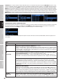
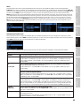
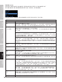
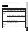
DEVICE CONFIGURATION (SETUP)
Menu item for editing device conguration, reading device rmware, resetting the device and managing global presets. Press the rotary MENUdial
to access the selection menu for device settings and turn the dial to select the menu item SETUP (bright background). Conrm by pressing the dial.
This will take you to the sub-menu with the following menu items (turn the MENU dial to select, then conrm by pressing MENU):
SETUP
FIRMWARE The device rmware version is displayed in the top line of the display.
NAME Congure individual amplier name (8 digits):
Press the MENU dial -> Turn the MENU dial to select 1 to 8 -> Press MENU -> Rotate MENU to select letters, numbers,
or characters -> Press MENU -> To exit, rotate MENU dial clockwise to arrow icon -> Press MENU.
PIN
ON / OFF / EDIT
Activate automatic locking of controls to prevent accidental and unauthorised
operation (except MASTER VOLUME, if enabled):
Press MENU twice -> Rotate MENU to ON -> Press MENU -> To exit, rotate MENU to arrow symbol -> Press MENU
Deactivate automatic locking:
Enter PIN to unlock menu (4-digit PIN factory setting: 1234) -> Rotate MENU to SETUP -> Press MENU -> Rotate MENU to
PIN -> Press MENU twice -> Rotate MENU to OFF Press MENU -> To exit, rotate MENU to arrow symbol -> Press MENU
Set personal PIN:
Press MENU twice -> Rotate MENU to EDIT Press MENU -> Rotate MENU to select 0 - 9 for rst digit -> Press MENU ->
Rotate MENU to select 0 -9 for second digit -> Press MENU etc. In the event of the PIN becoming lost, it can be reset to
the factory setting (1234) by using the PC software and USB interface (downloadable from the product page at WWW.
LD-SYSTEMS.COM).
DELAY UNIT
METRES / FEET
Conguring unit of measurement for channel delay METRES/FEET:
Press MENU -> Rotate MENU to select METERSor FEET -> Press MENU -> To exit, rotate MENU to arrow symbol
-> Press MENU
DELAY TEMP Conguring distance calculation based on air temperature (sound speed is dependent upon air temperature):
Press MENU twice -> Rotate MENU to select temperature from 0°C to 40°C -> Press MENU -> To exit, rotate MENU to
arrow symbol -> Press MENU
CONNECT GND
YES / NO
Floating switching for disconnecting the signal ground from equipment grounding
(to prevent ground loops):
Press MENU twice -> Rotate MENU to YES for ground connection / NO for ground lift -> Press MENU -> To exit, rotate
MENU to arrow symbol -> Press MENU
FACTORY SETTING
NO / YES
Reset to factory settings (e.g. resetting PIN to 1234 and OFF):
Press MENU -> Rotate MENU to NO = do not reset device / YES = reset device -> press MENU
GLOBAL PRESET Save all settings except amplier name and PIN in global presets
(16 internal memory slots):
Press MENU -> Rotate MENU to SAVE PRESET -> Press MENU -> Rotate MENU to desired memory slot -> Press MENU ->
Congure preset name: Rotate MENU to select digit (9 digits) -> Press MENU -> Rotate MENU to select letter, number
or character -> Press MENU etc. -> Rotate MENU to YES -> Press MENU -> Rotate MENU to EXIT to go back -> Press MENU
-> To exit, rotate MENU to EXIT -> Press MENU
Loading a global preset from internal memory:
Press MENU -> Rotate MENU to LOAD PRESET -> Press MENU -> Rotate MENU to required preset -> Press MENU ->
Rotate MENU to YES -> Press MENU -> Rotate MENU to EXIT to go back -> Press MENU -> To exit, rotate MENU to EXIT
-> Press MENU
SCREENSAVER
ON / OFF
Activate minimal display and reduced brightness (automatic activation after 5 minutes without input, display of channel
and audio level):
Press MENU 2x -> rotate MENU to ON for activated screensaver / OFF for deactivated screensaver -> press MENU
-> to exit rotate MENU to arrow symbol -> press MENU
EXIT SETUP To exit the setup-menu, rotate the MENU dial to EXIT SETUP and conrm by pressing MENU

10
DEUTSCHENGLISH FRANCAIS
ESPAÑOL
POLSKI ITALIANO
简体中文 繁體中文
EXIT
To exit the selection menu and show the main display, turn the MENU dial to EXIT (light background) and conrm by pressing the MENU dial.
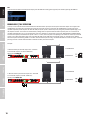
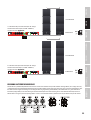
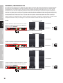
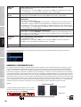
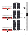
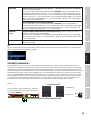
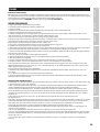
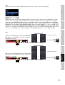
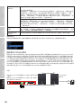
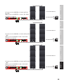
BRIDGE MODE / 70 V OPERATION
To set up a 70 V installation with the CURV 500 I AMP and CURV 500 satellites you require the LD Systems SmartLink adapter for 70 V applications
LDCURV500SLAT (available in black and white, please note the instructions in the user manual for the LDCURV500SLAT); if you wish to use the
speakON-compatible speaker output of the CURV 500 I AMP you require speaker cables with specially congured speakON-compatible plugs, since
two amplier channels can be connected simultaneously in bridge mode in conjunction with the relevant speaker preset. As an alternative to
speakON-compatible plugs, you can use terminal block connectors (supplied, for congurations see diagram CONFIGURATION OF SPEAKER OUTPUTS
or label on the amplier, recommended for speaker cables 2 x 1.5 mm²). Select the preset corresponding to the number of satellites per SmartLink
adapter as described under PRESET, then connect the CURV 500 I AMP and the CURV 500 SLAT SmartLink adapter. It is advisable not to combine
SmartLink adapters with differing numbers of satellites due to the different preset settings. The maximum number of SmartLink adapters connected
per bridge channel is derived from the number of CURV 500 satellites per SmartLink adapter.
Examples:
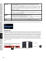
1 CURV 500 satellite per SmartLink adapter 70 V = maximum
of 24 SmartLink adapters (24 x 20 W = 480 W max.)
Speaker preset 1xC500-70V
1 x LDCURV500SAT
LDCURV500SLAT
1
24
2 CURV 500 satellites per SmartLink adapter 70 V = maximum
of 12 SmartLink adapters (12 x 40 W = 480 W max.)
Speaker preset 2xC500-70V
2 x LDCURV500SAT
LDCURV500SLAT
1 12

11
DEUTSCH
ENGLISHFRANCAIS
ESPAÑOL
POLSKIITALIANO
简体中文繁體中文
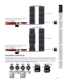
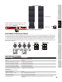
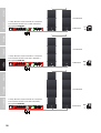
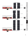
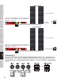
3 CURV 500 satellites per SmartLink adapter 70 V = maximum
of 8 SmartLink adapters (8 x 60 W = 480 W max.)
Speaker preset 3xC500-70V
3 x LDCURV500SAT
LDCURV500SLAT
1 8
4 CURV 500 satellites per SmartLink adapter 70 V = maximum
of 6 SmartLink adapters (6 x 80 W = 480 W max.)
Speaker preset 4xC500-70V
4 x LDCURV500SAT
LDCURV500SLAT
1 6
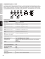
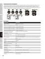
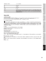
CONFIGURATION OF SPEAKER OUTPUTS
The speakON-compatible sockets and the terminal block connectors are wired in parallel. In bridge mode (BTL = Bridge Tied Load) / 70 V operation,
the speakON-compatible sockets B and D may NOT be assigned; this also applies to the minus pins of the terminal block connections. For signal
control, please note that the input routing can be freely congured (see ROUTING). A combination of two bridged amplier channels (bridge mode)
for controlling 70 V SmartLink adapters and controlling, for example, two CURV 500 ISUB speakers is possible in normal mode (e.g. channel A/B
bridge mode – channels C and D in normal mode). Select the appropriate speaker presets.

12
DEUTSCHENGLISH FRANCAIS
ESPAÑOL
POLSKI ITALIANO
简体中文 繁體中文
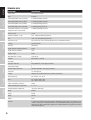
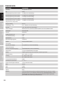
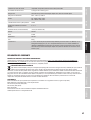
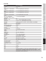
TECHNICAL DATA
Model number: LDCURV500IAMP
Product type: DSP controlled amplier
Type: 4-Channel
Rated output power (1 kHz @ 2,7 Ohm): 4 x 240 W (depending on preset)
Rated output power (1 kHz @ 4 Ohm): 4 x 240 W (depending on preset)
Rated output power (1 kHz @ 8 Ohm): 4 x 120 W (depending on preset)
Rated output power (1 kHz @ 16 Ohm): 4 x 60 W (depending on preset)
Rated power output BTL / 70 V operation
(Bridge Tied Load, 1 kHz @ 4 Ohm):
2 x 480 W (depending on preset)
Output circuitry: Class D
Frequency response +/- 1 dB: 10 Hz – 22000 Hz (depending on preset)
THD: < 0,01 % @ 1 kHz (depending on preset)
Protection circuits: Over-current, soft-start, DC, thermal overload, short circuit, multiband limiter
Controls: Push-turn-control
Indicators: OLED display
AD/DA converter sampling frequency: 48 kHz
AD/DA converter resolution: 24 Bit
Dynamic range: 114 dB
Maximum delay / Channel: 59 m/ 166 ms
Equalizer: 10x parametric / channel
Line inputs: 4
Line input connectors: XLR (symmetrical), screw-/plug-in-terminals
Loudspeaker outputs: 4
Speaker output connections: Speakon compatible, screw-/plug-in-terminals
Ground Lift: Yes, GUI integrated
Cooling: Temperature controlled low-noise fan, noiseless in idle mode
Operating voltage: 100 – 240 V AC / 50 – 60 Hz
Fuse: 110 – 120 V AC: T10AL / 250 V
220 – 240 V AC: T5AL / 250 V
Power consumption @ full load: 1100 W
Ambient temperature (in operation): 0 °C – 35 °C
Relative humidity (in operation): <80 % (non condensing)
Width: 482 mm
Height: 44 mm
Depth: 420 mm
Weight: 6.8 kg
Features: 4-channel DSP controlled, Purpose-designed for CURV500 installations, Smart 19"/ 1U housing, Each
channel can drive up to six CURV500 satellites or one CURV500ISUB subwoofer, Single push encoder
operation, High contrast OLED display, Temperature controlled low-noise fan, High efciency switch
mode power supply (PFC)

13
DEUTSCH
ENGLISHFRANCAIS
ESPAÑOL
POLSKIITALIANO
简体中文繁體中文
MANUFACTURER´S DECLARATIONS
MANUFACTURER‘S WARRANTY & LIMITATIONS OF LIABILITY
You can nd our current warranty conditions and limitations of liability at: https://cdn-shop.adamhall.com/media/pdf/MANUFACTURERS-
DECLARATIONS_LD_SYSTEMS.pdf .To request warranty service for a product, please contact Adam Hall GmbH, Adam-Hall-Str. 1,
61267 Neu Anspach / Email: [email protected] / +49 (0)6081 / 9419-0.
CORRECT DISPOSAL OF THIS PRODUCT
(valid in the European Union and other European countries with a differentiated waste collection system)
This symbol on the product, or on its documents indicates that the device may not be treated as household waste. This is to avoid environ-
mental damage or personal injury due to uncontrolled waste disposal. Please dispose of this product separately from other waste and have it
recycled to promote sustainable economic activity. Household users should contact either the retailer where they purchased this product, or their
local government ofce, for details on where and how they can recycle this item in an environmentally friendly manner. Business users should
contact their supplier and check the terms and conditions of the purchase contract. This product should not be mixed with other commercial waste
for disposal.
CE Compliance
Adam Hall GmbH states that this product meets the following guidelines (where applicable):
R&TTE (1999/5/EC) or RED (2014/53/EU) from June 2017
Low voltage directive (2014/35/EU)
EMV directive (2014/30/EU)
RoHS (2011/65/EU)
The complete declaration of conformity can be found at www.adamhall.com.
Furthermore, you may also direct your enquiry to [email protected].

14
DEUTSCHENGLISH FRANCAIS
ESPAÑOL
POLSKI ITALIANO
简体中文 繁體中文
DEUTSCH
SIE HABEN DIE RICHTIGE WAHL GETROFFEN!
Dieses Gerät wurde unter hohen Qualitätsanforderungen entwickelt und gefertigt, um viele Jahre einen reibungslosen Betrieb zu gewährleisten.
Dafür steht LD Systems mit seinem Namen und der langjährigen Erfahrung als Hersteller hochwertiger Audioprodukte. Bitte lesen Sie diese Bedie-
nungsanleitung sorgfältig, damit Sie Ihr neues Produkt von LD Systems schnell optimal einsetzen können.
Mehr Informationen zu LD SYSTEMS nden Sie auf unserer Internetseite WWW.LD-SYSTEMS.COM
SICHERHEITSHINWEISE
1. Lesen Sie diese Anleitung bitte sorgfältig durch.
2. Bewahren Sie alle Informationen und Anleitungen an einem sicheren Ort auf.
3. Befolgen Sie die Anweisungen.
4. Beachten Sie alle Warnhinweise. Entfernen Sie keine Sicherheitshinweise oder andere Informationen vom Gerät.
5. Verwenden Sie das Gerät nur in der vorgesehenen Art und Weise.
6. Verwenden Sie ausschließlich stabile und passende Stative bzw. Befestigungen (bei Festinstallationen). Stellen Sie sicher, dass Wandhalterungen
ordnungsgemäß installiert und gesichert sind. Stellen Sie sicher, dass das Gerät sicher installiert ist und nicht herunterfallen kann.
7. Beachten Sie bei der Installation die für Ihr Land geltenden Sicherheitsvorschriften.
8. Installieren und betreiben Sie das Gerät nicht in der Nähe von Heizkörpern, Wärmespeichern, Öfen oder sonstigen Wärmequellen. Sorgen Sie dafür,
dass das Gerät immer so installiert ist, dass es ausreichend gekühlt wird und nicht überhitzen kann.
9. Platzieren Sie keine Zündquellen wie z.B. brennende Kerzen auf dem Gerät.
10. Lüftungsschlitze dürfen nicht blockiert werden.
11. Halten Sie einen Mindestabstand von 20 cm seitlich und oberhalb des Geräts ein.
12. Betreiben Sie das Gerät nicht in unmittelbarer Nähe von Wasser. Bringen Sie das Gerät nicht mit brennbaren Materialien, Flüssigkeiten oder
Gasen in Berührung. Direkte Sonneneinstrahlung vermeiden!
13. Sorgen Sie dafür, dass kein Tropf- oder Spritzwasser in das Gerät eindringen kann. Stellen Sie keine mit Flüssigkeit gefüllten Behältnisse wie
Vasen oder Trinkgefäße auf das Gerät.
14. Sorgen Sie dafür, dass keine Gegenstände in das Gerät fallen können.
15. Betreiben Sie das Gerät nur mit dem vom Hersteller empfohlenen und vorgesehenen Zubehör.
16. Öffnen Sie das Gerät nicht und verändern Sie es nicht.
17. Überprüfen Sie nach dem Anschluss des Geräts alle Kabelwege, um Schäden oder Unfälle, z. B. durch Stolperfallen zu vermeiden.
18. Achten Sie beim Transport darauf, dass das Gerät nicht herunterfallen und dabei möglicherweise Sach- und Personenschäden
verursachen kann.
19. Wenn Ihr Gerät nicht mehr ordnungsgemäß funktioniert, Flüssigkeiten oder Gegenstände in das Geräteinnere gelangt sind, oder das Gerät an-
derweitig beschädigt wurde, schalten Sie es sofort aus und trennen es von der Netzsteckdose (sofern es sich um ein aktives Gerät handelt). Dieses
Gerät darf nur von autorisiertem Fachpersonal repariert werden.
20. Verwenden Sie zur Reinigung des Geräts ein trockenes Tuch.
21. Beachten Sie alle in Ihrem Land geltenden Entsorgungsgesetze. Trennen Sie bei der Entsorgung der Verpackung bitte Kunststoff und Papier bzw.
Kartonagen voneinander.
22. Kunststoffbeutel müssen außer Reichweite von Kindern aufbewahrt werden.
23. Sämtliche vom Benutzer vorgenommenen Änderungen und Modikationen, denen die für die Einhaltung der Richtlinien verantwortliche Partei
nicht ausdrücklich zugestimmt hat, können zum Entzug der Betriebserlaubnis für das Gerät führen.
BEI GERÄTEN MIT NETZANSCHLUSS
24. ACHTUNG: Wenn das Netzkabel des Geräts mit einem Schutzkontakt ausgestattet ist, muss es an einer Steckdose mit Schutzleiter angeschlossen
werden. Deaktivieren Sie niemals den Schutzleiter eines Netzkabels.
25. Schalten Sie das Gerät nicht sofort ein, wenn es starken Temperaturschwankungen ausgesetzt war (beispielsweise nach dem Transport). Feuch-
tigkeit und Kondensat könnten das Gerät beschädigen. Schalten Sie das Gerät erst ein, wenn es Zimmertemperatur erreicht hat.
26. Bevor Sie das Gerät an die Steckdose anschließen, prüfen Sie zuerst, ob die Spannung und die Frequenz des Stromnetzes mit den auf dem Gerät
angegebenen Werten übereinstimmen. Verfügt das Gerät über einen Spannungswahlschalter, schließen Sie das Gerät nur an die Steckdose an,
wenn die Gerätewerte mit den Werten des Stromnetzes übereinstimmen. Wenn das mitgelieferte Netzkabel bzw. der mitgelieferte Netzadapter
nicht in Ihre Netzsteckdose passt, wenden Sie sich an Ihren Elektriker.
27. Treten Sie nicht auf das Netzkabel. Sorgen Sie dafür, dass spannungsführende Kabel speziell an der Netzbuchse bzw. am Netzadapter und der
Gerätebuchse nicht geknickt werden.
28. Achten Sie bei der Verkabelung des Geräts immer darauf, dass das Netzkabel bzw. der Netzadapter stets frei zugänglich ist. Trennen Sie das
Gerät stets von der Stromzuführung, wenn das Gerät nicht benutzt wird, oder Sie das Gerät reinigen möchten. Ziehen Sie Netzkabel und Netzadapter
immer am Stecker bzw. am Adapter und nicht am Kabel aus der Steckdose. Berühren Sie Netzkabel und Netzadapter niemals mit nassen Händen.
29. Schalten Sie das Gerät möglichst nicht schnell hintereinander ein und aus, da sonst die Lebensdauer des Geräts beeinträchtigt werden könnte.
30. WICHTIGER HINWEIS: Ersetzen Sie Sicherungen ausschließlich durch Sicherungen des gleichen Typs und Wertes. Sollte eine Sicherung wiederholt
auslösen, wenden Sie sich bitte an ein autorisiertes Servicezentrum.
31. Um das Gerät vollständig vom Stromnetz zu trennen, entfernen Sie das Netzkabel bzw. den Netzadapter aus der Steckdose.
32. Wenn Ihr Gerät mit einem verriegelbaren Netzanschluss bestückt ist, muss der passende Gerätestecker entsperrt werden, bevor er entfernt wer-
den kann. Das bedeutet aber auch, dass das Gerät durch ein Ziehen am Netzkabel verrutschen und herunterfallen kann, wodurch Personen verletzt
werden und/oder andere Schäden auftreten können. Verlegen Sie Ihre Kabel daher immer sorgfältig.

15
DEUTSCH
ENGLISHFRANCAIS
ESPAÑOL
POLSKIITALIANO
简体中文繁體中文
33. Entfernen Sie Netzkabel und Netzadapter aus der Steckdose bei Gefahr eines Blitzschlags oder wenn Sie das Gerät länger nicht verwenden.
34. Das Gerät darf nicht von Personen (einschließlich Kindern) mit eingeschränkten körperlichen, sensorischen oder geistigen Fähigkeiten oder
mangelnder Erfahrung und Kenntnis benutzt werden.
35. Kinder müssen angewiesen werden, nicht mit dem Gerät zu spielen.
36. Wenn das Netzkabel des Geräts beschädigt ist, darf das Gerät nicht verwendet werden. Das Netzkabel muss durch ein adäquates Kabel oder eine
spezielle Baugruppe von einem autorisierten Service-Center ersetzt werden.
ACHTUNG
Entfernen Sie niemals die Abdeckung, da sonst das Risiko eines elektrischen Schlages besteht. Im In-
neren des Geräts benden sich keine Teile, die vom Bediener repariert oder gewartet werden können.
Lassen Sie Wartung und Reparaturen ausschließlich von qualiziertem Servicepersonal durchführen.
Das gleichseitige Dreieck mit Blitzsymbol warnt vor nichtisolierten, gefährlichen Spannungen im Geräteinneren, die einen elektrischen
Schlag verursachen können.
Das gleichseitige Dreieck mit Ausrufungszeichen kennzeichnet wichtige Bedienungs- und Wartungshinweise.
Warnung! Dieses Symbol kennzeichnet heiße Oberächen. Während des Betriebs können bestimmte Teile des Gehäuses heiß werden.
Berühren oder transportieren Sie das Gerät nach einem Einsatz erst nach einer Abkühlzeit von mindestens 10 Minuten.
Warnung! Dieses Gerät ist für eine Nutzung bis zu einer Höhe von maximal 2000 Metern über dem Meeresspiegel bestimmt.
Warnung! Dieses Gerät ist nicht für den Einsatz in tropischen Klimazonen bestimmt.
ACHTUNG HOHE LAUTSTÄRKEN BEI AUDIOPRODUKTEN!
Dieses Gerät ist für den professionellen Einsatz vorgesehen. Der kommerzielle Betrieb dieses Geräts unterliegt den jeweils gültigen nationalen
Vorschriften und Richtlinien zur Unfallverhütung. Als Hersteller ist Adam Hall gesetzlich verpichtet, Sie ausdrücklich auf mögliche Gesundheitsrisiken
hinzuweisen. Gehörschäden durch hohe Lautstärken und Dauerbelastung: Bei der Verwendung dieses Produkts können hohe Schalldruckpegel
(SPL) erzeugt werden, die bei Künstlern, Mitarbeitern und Zuschauern zu irreparablen Gehörschäden führen können. Vermeiden Sie länger anhaltende
Belastung durch hohe Lautstärken über 90 dB.
EINFÜHRUNG
Der I AMP ist eine 4-Kanal-Endstufe in 19“ Bauweise, die speziell zur Installation von CURV-500-Systemen entwickelt wurde. Das ache Design mit
Class-D-Topologie und DSP-Steuerung besitzt ein hochefzientes Schaltnetzteil und einen Frequenzgang von 10 Hz – 22 kHz. Jeder Kanal verfügt über
parametrische Klangregelung und Delay und leistet 240 Watt RMS an 4 Ohm bei einem Klirrfaktor unter 0,01%.
Der I AMP wird über einen Push-Encoder und das kontrastreiche, leicht lesbare OLED-Display ganz einfach und intuitiv bedient. Er ist mit einem Soft
Start und geräuscharmen temperaturgesteuerten Lüfter ausgestattet und gegen Gleichstrom, Überstrom, Überhitzung und Kurzschluss geschützt.
Die symmetrische Eingänge sind als XLR-Buchsen und Schraub-Steckverbindungen ausgeführt. Der I AMP kann pro Kanal bis zu sechs CURV-500-
Satelliten oder einen CURV500ISUB Subwoofer über speakON-kompatible Ausgangsbuchsen oder Schraub-Steckverbindungen ansteuern. Presets
für die Lautsprecher der CURV500 Serie sind vorinstalliert. Eine PC Software für die Verwaltung des I AMP ist auf der Produktseite auf
WWW.LD-SYSTEMS.COM als Download erhältlich.

16
DEUTSCHENGLISH FRANCAIS
ESPAÑOL
POLSKI ITALIANO
简体中文 繁體中文
ANSCHLÜSSE, BEDIEN- UND ANZEIGEELEMENTE
1
DISPLAY
Multifunktionales OLED-Grakdisplay für die Anzeige von Informationen wie z.B. Preset und Audiosignal-Pegel. Zeigt weiterhin die Menüpunkte an,
um Systemeinstellungen nach Wunsch vorzunehmen.
2
MENU
Kombinierter Drück-Dreh-Geber, um in das Bearbeitungsmenü zu gelangen und die einzelnen Menüpunkte auszuwählen und zu editieren.
3
LÜFTUNGSGITTER
Um Überhitzung des Geräts zu vermeiden, achten Sie darauf, dass das Lüftungsgitter nicht abgedeckt wird und Luft ungehindert zirkulieren kann.
4
NETZBUCHSE UND SICHERUNGSHALTER
IEC Netzbuchse mit integriertem Sicherungshalter. Ein geeignetes Netzkabel bendet sich im Lieferumfang.
WICHTIGER HINWEIS: Ersetzen Sie die Sicherung ausschließlich durch eine Sicherung des gleichen Typs. Achten Sie auf den Aufdruck auf dem
Gehäuse. Sollte die Sicherung wiederholt auslösen, wenden Sie sich bitte an ein autorisiertes Servicezentrum.
5
POWER ON / OFF
Ein- / Ausschalter für die Spannungszufuhr des Geräts.
6
OUTPUT CH A - CH D (speakON-kompatibel)
SpeakON-kompatible Lautsprecherausgänge der Kanäle A bis D. Um Schäden am Gerät zu vermeiden, achten Sie darauf, dass die Gesamtimpedanz
angeschlossener Lautsprecher pro Kanal minimal 2,7 Ohm beträgt. Die Kontakte der speakON-kompatiblen Buchsen und der Schraub-Steckverbin-
dungen der entsprechenden Kanäle sind parallel verdrahtet.
7
OUTPUT CH A - CH D (Schraub-Steckverbindung)
Lautsprecherausgänge der Kanäle A bis D mit Schraub-Steckverbindung (Schraub-Steckverbinder im Lieferumfang). Um Schäden am Gerät zu
vermeiden, achten Sie darauf, dass die Gesamtimpedanz angeschlossener Lautsprecher pro Kanal minimal 2,7 Ohm beträgt. Die Kontakte der
speakON-kompatiblen Buchsen und der Schraub-Steckverbindungen der entsprechenden Kanäle sind parallel verdrahtet.
8
INPUT IN 1 - 4 (3-Pol XLR)
Symmetrische Line-Eingänge der Kanäle 1 bis 4 mit 3-Pol XLR-Buchsen. Die Kontakte der XLR-Buchsen und der Schraub-Steckverbindungen der
entsprechenden Kanäle sind parallel verdrahtet.
9
INPUT IN 1 - 4 (Schraub-Steckverbindung)
Symmetrische Line-Eingänge der Kanäle 1 bis 4 mit Schraub-Steckverbindung (Schraub-Steckverbinder im Lieferumfang). Die Kontakte der
XLR-Buchsen und der Schraub-Steckverbindungen der entsprechenden Kanäle sind parallel verdrahtet.
10
DATA USB
USB-Schnittstelle (Typ B) zum Updaten der Geräte-Firmware und der Lautsprecher-Presets, zum Verwalten der Global Presets und zum Zurücksetzen
der Sperr-PIN. Das entsprechende Windows PC-Programm und aktuelle Update-Files nden Sie mit einer Anleitung im Download-Bereich des
Produkts auf WWW.LD-SYSTEMS.COM
10
GEHÄUSELÜFTER
Um Überhitzung des Geräts zu vermeiden, achten Sie darauf, dass die Lüfter nicht abgedeckt werden und Luft ungehindert zirkulieren kann.
4 5
6 7 8
9
11
10
11
1 32

17
DEUTSCH
ENGLISHFRANCAIS
ESPAÑOL
POLSKIITALIANO
简体中文繁體中文
BEDIENUNG
DISPLAY HAUPTANZEIGE
Nach dem Einschalten des Verstärkers wird als Begrüßungstext für kurz Zeit „WELCOME“ angezeigt, danach erscheint die Hauptanzeige mit
folgenden Informationen: Verstärkername (editierbar), Verstärkerkanal (CH A - D) mit Verlinkung, Lautsprecher-Preset, Audiopegel mit Peak-Anzeige
und Kanal-Stummschaltung (Mute). Erfolgt für circa 10 Minuten keine Eingabe, werden Teile der Anzeige ausgeblendet und nur Verstärkerkanal mit
Verlinkung, Audiopegel mit Peak-Anzeige und Kanal-Stummschaltung werden angezeigt.
Verstärkername
Verstärkerkanal
mit Verlinkung
Lautsprecher-Preset
Audiopegel mit Peak-Anzeige (PK)
und Kanal-Stummschaltung (Mute)
Verstärkerkanal
mit Verlinkung
Audiopegel mit Peak-Anzeige (PK)
und Kanal-Stummschaltung (Mute)
CHANNEL VOLUME
Menüpunkt für die Einstellung der Kanallautstärke. Drücken Sie auf den Drück-Dreh-Geber MENU, um ins Auswahlmenü für die Geräteeinstellungen
zu gelangen und wählen durch Drehen des Gebers den Menüpunkt CHANNEL VOLUME aus (hell hinterlegt). Drücken Sie nun auf den Geber und
wählen durch Drehen des Gebers den Kanal aus, dessen Lautstärke Sie ändern möchten. Drücken Sie wiederum auf den Geber und stellen die
gewünschte Lautstärke durch Drehen am Geber ein (Drehung nach links = Lautstärke reduzieren, Drehung nach links über -60dB hinaus = Mute,
Drehung nach rechts = Lautstärke anheben). Drücken und halten Sie den Geber für circa 2 Sekunden, um den angewählten Kanal stummzuschalten
(MUTE), bzw. die Stummschaltung wieder aufzuheben. Wenn Sie einen Kanal stummschalten, dann den Geber nach rechts drehen, um die Lautstärke
langsam anzuheben und dann für circa 2 Sekunden drücken, wird der letzte bestätigte Wert wiederhergestellt. Bestätigen Sie Eingaben durch
Drücken auf den Geber. Stellen Sie nun in gleicher Weise die Lautstärke für die anderen Kanäle nach Wunsch ein. Um zum Auswahlmenü zurückzuge-
langen, wählen Sie nun durch Drehen des Gebers den Menüpunkt CH VOLUME EXIT aus und bestätigen abermals durch Drücken auf den Geber. Zur
Hauptanzeige gelangen Sie, indem Sie nun durch Drehen am Geber EXIT auswählen (hell hinterlegt) und durch Drücken auf den Geber bestätigen.
Erfolgt circa 10 Sekunden keine Eingabe, erscheint automatisch die Hauptanzeige.

18
DEUTSCHENGLISH FRANCAIS
ESPAÑOL
POLSKI ITALIANO
简体中文 繁體中文
MASTER VOLUME
Die Einstellung der Gesamtlautstärke kann direkt aus der Hauptanzeige erfolgen, sofern diese Option im entsprechenden Menüpunkt aktiviert
wurde, selbst dann, wenn die Sperrung der Bedienelemente aktiviert wurde. Drücken Sie auf den Drück-Dreh-Geber MENU, um ins Auswahlmenü
für die Geräteeinstellungen zu gelangen und wählen durch Drehen des Gebers den Menüpunkt MASTER VOLUME aus (hell hinterlegt). Drücken Sie
nun 2-mal auf den Geber, wählen durch Drehen des Gebers nach links „ON“ aus und bestätigen die Eingabe durch Drücken auf den Geber (Soll die
Einstellung der Gesamtlautstärke nicht verfügbar sein, wählen Sie entsprechend „OFF“ aus). Wählen Sie nun durch Drehen am Geber das Pfeilsymbol
aus und bestätigen durch Drücken auf den Geber, um in das Auswahlmenü zurückzugelangen. Um zur Hauptanzeige zurückzugelangen, wählen
Sie nun durch Drehen des Gebers den Menüpunkt EXIT aus und bestätigen abermals durch Drücken auf den Geber. Erfolgt circa 10 Sekunden keine
Eingabe, erscheint automatisch die Hauptanzeige.
Sie können nun die Gesamtlautstärke einstellen, indem Sie den Drück-Dreh-Geber MENU in die gewünschte Richtung drehen, ohne ihn vorher zu drücken
(Drehung nach links = Lautstärke reduzieren, Drehung nach rechts = Lautstärke anheben). Die Anzeige im Display wechselt dabei auf MASTER VOLUME
(0 bis 100). Nach circa 2 Sekunden ohne Eingabe erscheint automatisch die Hauptanzeige.
DELAY
Menüpunkt für die Einstellung der Kanalverzögerung (z.B. Delay-Line). Drücken Sie auf den Drück-Dreh-Geber MENU, um ins Auswahlmenü für die
Geräteeinstellungen zu gelangen und wählen durch Drehen des Gebers den Menüpunkt DELAY aus (hell hinterlegt). Drücken Sie nun auf den Geber
und wählen durch Drehen des Gebers den Kanal aus, dessen Verzögerung (Delay) Sie einstellen möchten. Drücken Sie wiederum auf den Geber und
stellen den gewünschten Wert durch Drehen am Geber ein (Drehung nach links = maximale Verzögerung, Drehung nach rechts = Feineinstellung ab 0ms). Die
Verzögerung wird sowohl in Millisekunden (ms), als auch in Metern (m), bzw. Feet (ft) angezeigt (siehe SETUP -> DELAY UNIT). Bestätigen Sie die Eingabe durch
Drücken auf den Geber. Stellen Sie nun in gleicher Weise die Verzögerung für die anderen Kanäle nach Wunsch ein. Um zum Auswahlmenü zurückzugelangen,
wählen Sie nun durch Drehen des Gebers den Menüpunkt DELAY EXIT aus und bestätigen abermals durch Drücken auf den Geber. Zur Hauptanzeige gelan-
gen Sie, indem Sie nun durch Drehen am Geber EXIT auswählen (hell hinterlegt) und durch Drücken auf den Geber bestätigen. Erfolgt circa 10 Sekunden
keine Eingabe, erscheint automatisch die Hauptanzeige.
ROUTING
Menüpunkt zum Einstellen der Eingangsquelle in den Kanälen A bis D. Drücken Sie auf den Drück-Dreh-Geber MENU, um ins Auswahlmenü für die Geräte-
einstellungen zu gelangen und wählen durch Drehen des Gebers den Menüpunkt ROUTING aus (hell hinterlegt). Drücken Sie nun auf den Geber und
wählen durch Drehen des Gebers die Eingangsquelle aus, die Sie kongurieren möchten (Kanal A - D, jeweils Eingangsquelle 1 - 4). Drücken Sie wiederum
auf den Geber, wählen die gewünschte Einstellung durch Drehen am Geber aus (Zahl mit Rahmen = Eingangsquelle aktiviert, Zahl ohne Rahmen =
Eingangsquelle deaktiviert) und bestätigen die Eingabe durch Drücken auf den Geber. Um zum Auswahlmenü zurückzugelangen, wählen Sie nun
durch Drehen des Gebers den Menüpunkt ROUTING EXIT aus und bestätigen abermals durch Drücken auf den Geber. Zur Hauptanzeige gelangen
Sie, indem Sie nun durch Drehen am Geber EXIT auswählen (hell hinterlegt) und durch Drücken auf den Geber bestätigen. Erfolgt circa 10 Sekunden
keine Eingabe, erscheint automatisch die Hauptanzeige.

19
DEUTSCH
ENGLISHFRANCAIS
ESPAÑOL
POLSKIITALIANO
简体中文繁體中文
EQUALIZER
Menüpunkt zum Einstellen des 10-Band parametrischen Equalizers in den Kanälen A bis D. Drücken Sie auf den Drück-Dreh-Geber MENU, um ins Aus-
wahlmenü für die Geräteeinstellungen zu gelangen und wählen durch Drehen des Gebers den Menüpunkt EQUALIZER aus (hell hinterlegt). Drücken
Sie nun auf den Geber und wählen durch Drehen des Gebers den Kanal aus, den Sie bearbeiten möchten (Kanal A - D). Drücken Sie wiederum auf
den Geber, wählen das gewünschte Equalizer-Band 01 bis 10 durch Drehen am Geber aus und bestätigen durch Drücken auf den Geber. Wählen Sie
nun durch Drehen des Gebers FREQ (Frequenz), Q (Filtergüte, Low Shelf LS und High Shelf HS) und GAIN (Verstärkung) aus, bestätigen durch Drücken
auf den Geber, bearbeiten den entsprechenden Parameter nach Wunsch und bestätigen durch Drücken auf den Geber. Um zur Kanalauswahl zu-
rückzugelangen, wählen Sie nun durch Drehen des Gebers nach rechts den Menüpunkt EXIT EQ aus und bestätigen abermals durch Drücken auf den
Geber. Stellen Sie nun in zuvor beschriebener Weise die Equalizer der anderen Kanäle nach Wunsch ein. Zur Hauptanzeige gelangen Sie, indem Sie
nun durch Drehen am Geber EXIT auswählen (hell hinterlegt) und durch Drücken auf den Geber bestätigen. Erfolgt circa 10 Sekunden keine Eingabe,
erscheint automatisch die Hauptanzeige.
POLARITY
Menüpunkt zum Einstellen der Polarität der Kanäle A bis D. Drücken Sie auf den Drück-Dreh-Geber MENU, um ins Auswahlmenü für die Geräteein-
stellungen zu gelangen und wählen durch Drehen des Gebers den Menüpunkt POLARITY aus (hell hinterlegt). Drücken Sie nun auf den Geber und
wählen durch Drehen des Gebers den Kanal aus, den Sie bearbeiten möchten (Kanal A - D). Drücken Sie wiederum auf den Geber, wählen durch
Drehen am Geber die Polarität wie gewünscht aus und bestätigen durch Drücken auf den Geber (NORMAL = normale Polarität, INVERTED = invertierte
Polarität). Stellen Sie nun in gleicher Weise die Polarität anderen Kanäle nach Wunsch ein. Um zum Auswahlmenü zurückzugelangen, wählen Sie nun
durch Drehen des Gebers den Menüpunkt POLARITY EXIT aus und bestätigen abermals durch Drücken auf den Geber. Zur Hauptanzeige gelangen Sie,
indem Sie nun durch Drehen am Geber EXIT auswählen (hell hinterlegt) und durch Drücken auf den Geber bestätigen. Erfolgt circa 10 Sekunden keine
Eingabe, erscheint automatisch die Hauptanzeige.

20
DEUTSCHENGLISH FRANCAIS
ESPAÑOL
POLSKI ITALIANO
简体中文 繁體中文
LINK SETT
Die Kanäle A bis D können beliebig verknüpft werden, um Lautstärke-, Delay- und Equalizer-Einstellungen in den ausgewählten Kanälen parallel
durchführen zu können. Das heißt, dass Einstellungen, die in einem der miteinander verknüpften Kanäle vorgenommen werden, simultan von den
anderen verknüpften Kanälen übernommen werden. Werte, die vor der Verlinkung eingestellt wurden, bleiben so lange erhalten, bis der Wert des ent-
sprechenden Parameters verändert wird. Das heißt, dass erst beim Ändern eines Werts in einem Kanal, der Wert im verlinkten Kanal übernommen wird.
Drücken Sie auf den Drück-Dreh-Geber MENU, um ins Auswahlmenü für die Geräteeinstellungen zu gelangen und wählen durch Drehen des Gebers den
Menüpunkt LINK SETT. aus (hell hinterlegt). Drücken Sie nun auf den Geber und wählen durch Drehen des Gebers den Kanal aus, den Sie mit anderen
Kanälen verknüpfen möchten. Drücken Sie wiederum auf den Geber und wählen die gewünschte Verknüpfung durch Drehen am Geber aus (UNLINK
für das Lösen einer Verknüpfung). Bestätigen Sie die Auswahl durch Drücken auf den Geber. Eine Verknüpfung wird durch einen „Verbindungsbalken“
zwischen den entsprechenden Buchstaben im Display grasch dargestellt. Um zur Hauptanzeige zurückzugelangen, wählen Sie nun durch Drehen des
Gebers den Menüpunkt LINK EXIT aus und bestätigen abermals durch Drücken auf den Geber. Um zur Hauptanzeige zurückzugelangen, wählen Sie durch
Drehen am Geber EXIT aus (hell hinterlegt) und bestätigen durch Drücken auf den Geber. Erfolgt circa 10 Sekunden keine Eingabe, erscheint automatisch
die Hauptanzeige.
PRESET
Menüpunkt für die Auswahl der Lautsprecher-Presets für die Lautsprecher der LD CURV Serie. Wählen Sie beispielsweise das Preset 6 CURV-SAT,
wenn Sie am entsprechenden Kanal 6 Stück CURV 500 Array Satelliten am SmartLink® Adapter, das Preset 1 CURV-SUB, wenn Sie den CURV 500
Installations-Subwoofer anschließen möchten (Hinweis: Wählen Sie das der Anzahl der Satelliten pro SmartLink
®
Adapter entsprechende Preset
aus). Drücken Sie auf den Drück-Dreh-Geber MENU, um ins Auswahlmenü für die Geräteeinstellungen zu gelangen und wählen durch Drehen des
Gebers den Menüpunkt PRESET aus (hell hinterlegt). Drücken Sie nun auf den Geber und wählen durch Drehen des Gebers den Kanal aus, für den Sie
das gewünschte Preset einstellen möchten. Drücken Sie wiederum auf den Geber und wählen das gewünschte Preset durch Drehen am Geber aus.
Bestätigen Sie die Auswahl durch Drücken auf den Geber. Stellen Sie nun in gleicher Weise die Presets für die anderen Kanäle ein. Um zur Hauptan-
zeige zurückzugelangen, wählen Sie nun durch Drehen des Gebers den Menüpunkt PRESET EXIT aus und bestätigen abermals durch Drücken auf den
Geber. Um zur Hauptanzeige zurückzugelangen, wählen Sie durch Drehen am Geber EXIT aus (hell hinterlegt) und bestätigen durch Drücken auf den
Geber. Erfolgt circa 10 Sekunden keine Eingabe, erscheint automatisch die Hauptanzeige.
GERÄTEKONFIGURATION (SETUP)
Menüpunkt zum Editieren von Gerätekonguration, zum Auslesen der Geräte-Firmware, zum Zurücksetzen des Geräts und zum Verwalten der Global
Presets. Drücken Sie auf den Drück-Dreh-Geber MENU, um ins Auswahlmenü für die Geräteeinstellungen zu gelangen, wählen durch Drehen des
Gebers den Menüpunkt SETUP aus (hell hinterlegt) und bestätigen durch Drücken auf den Geber.
La page est en cours de chargement...
La page est en cours de chargement...
La page est en cours de chargement...
La page est en cours de chargement...
La page est en cours de chargement...
La page est en cours de chargement...
La page est en cours de chargement...
La page est en cours de chargement...
La page est en cours de chargement...
La page est en cours de chargement...
La page est en cours de chargement...
La page est en cours de chargement...
La page est en cours de chargement...
La page est en cours de chargement...
La page est en cours de chargement...
La page est en cours de chargement...
La page est en cours de chargement...
La page est en cours de chargement...
La page est en cours de chargement...
La page est en cours de chargement...
La page est en cours de chargement...
La page est en cours de chargement...
La page est en cours de chargement...
La page est en cours de chargement...
La page est en cours de chargement...
La page est en cours de chargement...
La page est en cours de chargement...
La page est en cours de chargement...
La page est en cours de chargement...
La page est en cours de chargement...
La page est en cours de chargement...
La page est en cours de chargement...
La page est en cours de chargement...
La page est en cours de chargement...
La page est en cours de chargement...
La page est en cours de chargement...
La page est en cours de chargement...
La page est en cours de chargement...
La page est en cours de chargement...
La page est en cours de chargement...
La page est en cours de chargement...
La page est en cours de chargement...
La page est en cours de chargement...
La page est en cours de chargement...
La page est en cours de chargement...
La page est en cours de chargement...
La page est en cours de chargement...
La page est en cours de chargement...
La page est en cours de chargement...
La page est en cours de chargement...
La page est en cours de chargement...
La page est en cours de chargement...
La page est en cours de chargement...
La page est en cours de chargement...
La page est en cours de chargement...
La page est en cours de chargement...
La page est en cours de chargement...
La page est en cours de chargement...
La page est en cours de chargement...
La page est en cours de chargement...
La page est en cours de chargement...
La page est en cours de chargement...
La page est en cours de chargement...
La page est en cours de chargement...
La page est en cours de chargement...
La page est en cours de chargement...
La page est en cours de chargement...
La page est en cours de chargement...
La page est en cours de chargement...
La page est en cours de chargement...
La page est en cours de chargement...
La page est en cours de chargement...
La page est en cours de chargement...
La page est en cours de chargement...
-
 1
1
-
 2
2
-
 3
3
-
 4
4
-
 5
5
-
 6
6
-
 7
7
-
 8
8
-
 9
9
-
 10
10
-
 11
11
-
 12
12
-
 13
13
-
 14
14
-
 15
15
-
 16
16
-
 17
17
-
 18
18
-
 19
19
-
 20
20
-
 21
21
-
 22
22
-
 23
23
-
 24
24
-
 25
25
-
 26
26
-
 27
27
-
 28
28
-
 29
29
-
 30
30
-
 31
31
-
 32
32
-
 33
33
-
 34
34
-
 35
35
-
 36
36
-
 37
37
-
 38
38
-
 39
39
-
 40
40
-
 41
41
-
 42
42
-
 43
43
-
 44
44
-
 45
45
-
 46
46
-
 47
47
-
 48
48
-
 49
49
-
 50
50
-
 51
51
-
 52
52
-
 53
53
-
 54
54
-
 55
55
-
 56
56
-
 57
57
-
 58
58
-
 59
59
-
 60
60
-
 61
61
-
 62
62
-
 63
63
-
 64
64
-
 65
65
-
 66
66
-
 67
67
-
 68
68
-
 69
69
-
 70
70
-
 71
71
-
 72
72
-
 73
73
-
 74
74
-
 75
75
-
 76
76
-
 77
77
-
 78
78
-
 79
79
-
 80
80
-
 81
81
-
 82
82
-
 83
83
-
 84
84
-
 85
85
-
 86
86
-
 87
87
-
 88
88
-
 89
89
-
 90
90
-
 91
91
-
 92
92
-
 93
93
-
 94
94


LD Systems CURV 500 I AMP Manuel utilisateur
- Taper
- Manuel utilisateur
- Ce manuel convient également à
dans d''autres langues
Documents connexes
-
LD Systems DJ 500 Manuel utilisateur
-
-
-
LD Systems DAVE 8XS Manuel utilisateur
-
-
LD Systems DSP 45 K Manuel utilisateur
-
-
LD Systems LDCURV500I Managing Software Manuel utilisateur
-
-
Autres documents
-
LD CURV 500 TS Manuel utilisateur
-
LD Systems Road Buddy 10 Le manuel du propriétaire
-
Yamaha AW2400 Manuel utilisateur
-
-
Yamaha PSR-A3000 Le manuel du propriétaire
-
Yamaha NULL Le manuel du propriétaire
-
LG MDS715 Manuel utilisateur
-
 FOCAL NAIM Deutschland ISUB-ACTIVE-2.1 Le manuel du propriétaire
-
Monacor ESUB-6W/WS Installation Instructions Manual
