
A product by
Instruction Manual
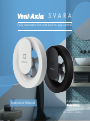
Fully automatic fan with built in app control
SVARA
009-500032-C_20201211


EN Fully automatic fan with built in app control
FR Ventilateur automatique, contrôlé par
une application
NL Automatische ventilator met app-sturing
DE Automatische App-gesteuerter Bad- und
Küchenventilator
EN Important Information 4
Installation and Wiring Instructions 5-13
Pin Code for app 44
Accessories 45
FR Informations importantes 14
Manuel d’installation et d’utilisation 15-23
Code Pin pour app 44
Accessoires 45
NL Belangrijke informatie 24
Gebruiks- en installatiehandleiding 25-33
Pincode voor app 44
Toebehoren 45
DE Wichtig 34
Benutzer - und Installationshandbuch 35-43
Pin-Code zur Appsteuerung 44
Zubehör 45
Article reference / Référence d’article / Artikelnummer / Artikelnummer
white / blanc / wit / weiß
BE/FR 1001000308 - NL/DE 8000000001
black / noir / zwart / schwarz
BE/FR 1001000310 - NL/DE 8000001283

EN
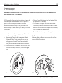
4 Operating and installation instructions
DO NOT install this product in areas where the
following may be present or occur:
• Excessive oil or a grease laden atmosphere.
• Corrosive or flammable gases, liquids or vapours.
• Ambient temperatures are outside 5-50°C.
• Possible obstructions which would hinder the access or
removal of the Fan.
SAFETY AND GUIDANCE NOTES
A. All wiring to be in accordance with the current I.E.E.
Regulations, or the appropriate standards of your
country and MUST be installed by a suitably qualified
person.
B. The Fan should be provided with a local isolator switch
capable of disconnecting all poles, having a contact
separation of at least 3mm.
C. Ensure that the mains supply (Voltage, Frequency, and
Phase) complies with the rating label.
D. The Fan should only be used in conjunction with the
appropriate Vent-Axia products.
E. The fan should only be used in conjunction with fixed
wiring.
F. The Fan should not be used where it is liable to be
subject to direct water spray for prolonged periods of
time.
G. Where ducted Fans are used to handle moisture-laden
air, a condensation trap should be fitted. Horizontal
ducts should be arranged to slope slightly downwards
away from the Fan.
H. This appliance is not intended for use by young children
or infirm persons without supervision.
I. Young children should be supervised to ensure that they
do not play with the appliance.
J. The exterior grille should be at least 2.3m above the
ground to prevent people from being able to access
moving parts. If the external grille is positioned
between 0-2.3m from the ground, please use the Vent-
Axia wall kit to ensure people cannot access the fans
impeller from the outside.
Important: READ THESE INSTRUCTIONS BEFORE COMMENCING THE INSTALLATION

EN
5Operating and installation instructions
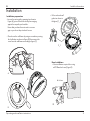
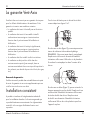
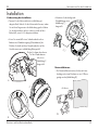
Installer information
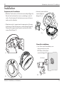
Installation
Installation preparation
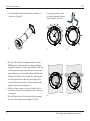
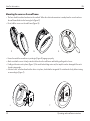
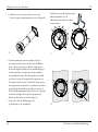
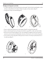
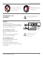
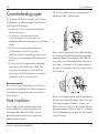
• Loosen the motor unit by grasping it as shown in
Figure (A), prise off the motor unit by leaveraging
against the cap with your knuckles.
Ensure that you have the motor unit in a secure
grip so you do not drop it when it loosens.
• Then loosen the wall frame by using a screwdriver pressing
the lock button as shown in Figure (B) then remove the
cover from the wall frame according to figure (C).
B.
C
C_1.
A.
5 mm
Ø 110 mm
D.
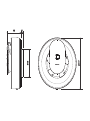
New Installations
• New installations require holes using
a Ø110 mm hole saw (Figure D).
• Fit the enclosed wall
gasket as shown in
the figure (C_1).

EN
6 Operating and installation instructions
E.
F.
R75
45°
45°
45°
45°
G.
H.
I.
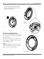
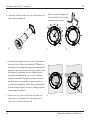
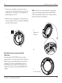
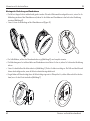
• The fan’s wall seal has a short spigot which fits inside the
Ø100 mm pipe. Make sure when mounting to adapt the
length of the wall pipe so it does not push back the wall seal
so the fan impeller cannot rotate. Always customise a wall
pipe, existing or new, so it ends about 5 mm inside the wall
surface where the fan is to be installed. The wall frame with
its seal is prepared with 5 cable entry points (Figure F) for
concealed electrical connection or surface-mounted cable
using the dimension shown in Figure G.
• Make sure that the gasket is properly installed on the
wall frame, place it in the appropriate place and centre
it in the pipe.
• The wall frame can be offset horizontally by placing a
spirit level on its support points (Figure H and I).
Installer information
• Vent-Axia wall kits and external grilles are available as
accessories. (Figure E).
Use ageing-resistant sealant
to seal around cables that are
laid through the wall seal.

EN
7Operating and installation instructions
R75
30°
65°
95°
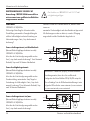
J.
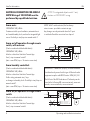
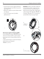
Always use a qualified electrician
All electrical connections 100-240V must be performed by a
qualified electrician. Any electrical work on the product must
utilise a voltage break.
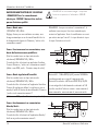
Electrical connection can be made according to the wiring
diagram on page 6-7 and the fan is suitable for connection
to either 100-240VAc or 12VDC.
NOTE: The internal cable route must be as indicated as
figures K/K1 (240VAC) and L (12VDC) to prevent the cable
blocking the locator’s for the motor assembly.
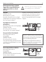
• Mark the three attachment points for the appropriate
screws to the substrate (Figure J). Tighten the screws so
that gasket seals against the wall.
K.
K1.
L.
100-240 V AC
connection
12 V DC connection
Installer information

EN
8 Operating and installation instructions
NOTE! The integrated all-pole switch S only
functions at 100-240VAC wiring.
Svara auto:
100-240VAC 50 / 60Hz
Continuous trickle speed ventilation, automatic boost
at elevated humidity levels, and via the integrated light
sensor. Possibility to start/stop via manual switch T.
Svara on/off operation through remote
switch, with overrun:
(Can be combined with backdraft shutter)
100-240VAC 50 / 60Hz
Must be selected via Vent-Axia Connect App.
Start / stop via manual switch T.
(start = max. RPM, stop = 15 minutes run-on time)
Svara humidity controlled:
(Can be combined with backdraft shutter)
100-240VAC 50 / 60Hz
Must be selected via Vent-Axia Connect App.
Trickle setting, automatic start / stop
on changes in humidity levels. Possibility to start/stop via
manual switch T.
(start = max. RPM, stop = 15 minutes run-on time)
Svara on/off operation through remote
switch:
(Can be combined with backdraft shutter)
100-240VAC 50 / 60Hz
Must be selected via Vent-Axia Connect App.
Start / stop via manual switch L.
NOTE: With T switch activated, the fan always
returns to max. speed after contact via app.
Any changes are only activated when the T input
is switched off and the run-on time has elapsed.
ELECTRICAL CONNECTION 100-240VAC
NOTE! Wiring of 100-240VAC must be
performed by a qualified electrician.
Installer information
Bluetooth LE: -12dBm EIRP (63μW), nominal 2450MHz
Vent-Axia hereby assure that this type of Bluetooth radio
equipment complies with RED Directive 2014/53 / EU.
The full text of the EU Declaration of Conformity can be
found at the following URL: www.vent-axia.nl, www.vent-
axia.be, www.vent-axia.de, www.vent-axia.fr.

EN
9Operating and installation instructions
Connection of 100-240VAC
and 12VDC can not be done
simultaneously (Figure N).
NOTE! 12VDC voltage must not exceed
between 10 - 13,6VDC.
NOTE! For 12VDC always use switches
intended for direct current, C.
N. O.
No 100-240V wiring may
penetrate the electronics
portion (Figure O).
Svara auto:
12VDC (switch C always)
Continuous trickle ventilation, automatic boost at elevated
humidity levels, and via the integrated light sensor.
Svara on/off operation through remote
switch:
(Can be combined with backdraft shutters)
12VDC
Must be selected via Vent-Axia Connect App.
Start / stop via manual switch C.
Svara humidity controlled:
(Can be combined with backdraft shutters)
12VDC (switch C always)
Must be selected via Vent-Axia Connect App.
Trickle setting, automatic start / stop
on changes in humidity levels.
ELECTRICAL CONNECTION 12VDC
Installer information

EN
10 Operating and installation instructions
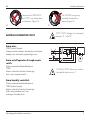
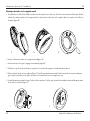
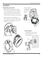
Mounting the cover on the wall frame
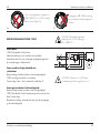
• The fan is double insulated and must not be earthed. When the electrical connection is made place the cover back over
the wall frame fitted into the housing hole (Figure P).
• Next, fold the cover over the wall frame (Figure Q).
Q.
R.
P.
T.
S.
• Ensure the catch the screwdriver is pointing to (Figure R) engages properly.
• Make sure that the cover is firmly seated in the hook on the wall frame and latch by pulling a bit of cover.
• Finally put the motor unit in place (Figure S). Be careful when fitting motor unit, the impellor can be damaged if the unit is
forced in at an angle.
• A distinct ’click’ sound confirms that the device is in place, check that the integrated On switch works freely before turning
on according to (Figure T).
Installer information

EN
11Operating and installation instructions
Default setting:
Vent-Axia Svara is programmed to cope with the vast
majority of installations. The fan works continuously at a
trickle flow of 30m³/h.
When the fan senses somebody in the room it increases
the flow to 60m³/h. If the humidity rises rapidly, for
example when the shower is on, the fan goes up to
maximum flow at 95m³/h.
When the fan senses the humidity level has returned to
normal it reverts to the trickle flow of 30m³/h.
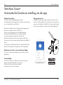
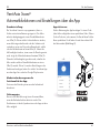
If other settings or functions are desired, download
the Vent-Axia Connect App from the App Store and
Google Play.
Minimal requirements for Vent-Axia
Connect App:
Versions of the operating system are updated
continuously.
Fault indication:
Red LED on the fan indicates power failure when the
calendar function has been activated.
Vent-Axia Svara
®
Automatic functions and settings via app
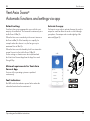
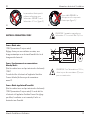
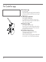
Activate the app:
You have to use a code to activate the app, the code is
unique for each fan. Enter the code or scan it through
your phone. Your unique code is on the right leg of the
motor unit (Figure U).
U.
For the user

EN
12 Operating and installation instructions
Strong solvents should not be used on the fan.
The fan must not be dipped in or sprayed with water. For the
fan to operate correctly it must be cleaned at least twice a
year, more often if
necessary.
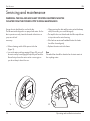
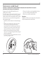
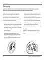
• Before cleaning, switch off the power to the fan
(Figure V).
• Loosen the motor unit by grasping it (Figure W), prise off
the motor unit by leaveraging the cap with your knuckles.
Ensure that you have the motor unit in a secure grip so
you do not drop it when it loosens.
• Clean opening, the duct and the motor unit with a damp
cloth (if necessary, use a mild detergent).
• The impellor does not detach and should be wiped clean
in its position on the motor housing
• If the fan has an external backdraft shutter the shutter
should be cleaned gently.
• Replace the motor unit in the frame.
Eco
Discarded fans should be submitted as electronic waste to
the recycling centre.
Servicing and maintenance
WARNING: THE FAN AND ANCILLARY CONTROL EQUIPMENT MUST BE
ISOLATED FROM THE POWER SUPPLY DURING MAINTENANCE.
V. W.
For the user

EN
13Operating and installation instructions
The Vent-Axia
Guarantee
Vent-Axia guarantees its Lo-Carbon products for five years
from date of purchase against faulty material or workman-
ship. In the event of any part being found to be defective,
the product will be repaired, or at the Company’s option
replaced, without charge, provided that the product:
• Has been installed and used in accordance with the
instructions given with each unit.
• Has not been connected to an unsuitable electricity
supply. (The correct electricity supply voltage is shown
on the product rating label attached to the unit).
• Has not been subjected to misuse, neglect or damage.
• Has not been modified or repaired by any person not
authorised by the company.
If claiming under terms of warranty
Please return the complete product to your original sup-
plier. The warranty is offered to you as an extra benefit,
and does not affect your legal rights.
Solid Installation
This product conforms to industry regulations for electrical
safety. Supplier guarantees the functioning of the relevant
regulations and instructions are complied with.
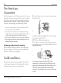
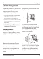
For Wooden wallcoverings (Figure X), drill only through
the coating and waterproofing.
NOTE: Never drill through any plywood.
Fill the entire hole with age-resistant sealing compound.
Use plumbing screws, screw through the plywood into the
regulatory framework.
X.
Y.
For concrete wet room walls (Figure Y), drill the
appropriate hole depth for the plug. Fill the hole with
age-resistant sealing compound. Push the plug into the
hole. Fill the entire plug with age-resistant sealing
compound. Use plumbing screws and screw the product
in place.
For the user
All the holes for the screws to be carried out according to
the figures X and Y.

FR
14 Manuel d’installation et d’utilisation
NE PAS installer ce produit dans des espaces où les
éléments suivants peuvent être présents ou se produire :
• Une atmosphère excessivement chargée en huile ou
graisse.
• Des gaz, liquides ou vapeurs corrosifs ou inflammables.
• Des températures ambiantes en dehors de la plage
5-50°C.
• Des obstructions possibles qui gêneraient l’accès ou le
retrait du ventilateur.
CONSIGNES DE SECURITE ET DE GUIDAGE
A. Tout le câblage DOIT être en conformité avec les
réglementations actuelles EEI, ou les normes appropriées
de votre pays et DOIT être installé par une personne
dûment qualifiée.
B. Le ventilateur doit être muni d’un interrupteur de proximité
capable de déconnecter tous les pôles, ayant une
séparation de contact d’au moins 3mm.
C. Veillez à ce que l’alimentation secteur (tension, fréquence
et phase) soit conforme à l’étiquette signalétique.
D. Le ventilateur ne peut être utilisé conjointement qu’avec
des produits Vent-Axia appropriés.
E. Le ventilateur ne peut être utilisé conjointement qu’avec un
câblage fixe.
F. Le ventilateur ne doit pas être utilisé là où il est sujet à des
projections d’eau directe pour des périodes de temps
prolongées.
G. Lorsque des ventilateurs canalisés sont utilisés pour
gérer de l’air chargé en humidité, une évacuation des
condensats doit être installée. Les conduits horizontaux
doivent être légèrement inclinés vers l’extérieur du
ventilateur.
H. Cet appareil n’est pas destiné à être utilisé par de
jeunes enfants ou des personnes sans qualification sans
surveillance.
I. Les jeunes enfants doivent être surveillés pour s’assurer
qu’ils ne jouent pas avec l’appareil.
J. L’extracteur devrait être au moins à 2,3m au-dessus du
sol pour empêcher d’accéder à des pièces mobiles. Si
la grille extérieure est positionnée entre 0 et 2,3m du sol,
veuillez utiliser le kit pour mur Vent-Axia pour veiller à ce
que des personnes ne puissent pas accéder aux hélices
du ventilateur depuis l’extérieur.
Important: VEUILLEZ LIRE ATTENTIVEMENT LES INSTRUCTIONS DU PRÉSENT MANUEL AVANT
D’UTILISER L’APPAREIL.

FR
15Manuel d’installation et d’utilisation
Préparation de l’installation
• Détachez l’unité moteur en la tenant comme indiqué (figure A).
Retirez l’unité en faisant levier avec vos phalanges contre le
cache. Tenez fermement l’unité moteur pour ne pas la laisser
tomber une fois détachée.
• Détachez ensuite le support mural en appuyant sur le bouton
de blocage à l’aide d’un tournevis, comme indiqué (figure B).
Démontez du support mural la partie supérieure du cache,
comme illustré (figure C).
Informations destinées à l’installateur
Installation
B.
C
C_1.
A.
5 mm
Ø 110 mm
D.
Nouvelles installations
• Lors d’une nouvelle installation, vous
devez percer des trous de
Ø 110 mm à l’aide d’une
scie-cloche (figure D).
•Montez le joint mural fourni
comme indiqué sur
la figure (C_1).

FR
16 Manuel d’installation et d’utilisation
E.
F.
R75
45°
45°
45°
45°
G.
H.
I.
• Le joint mural du ventilateur présente une pièce d’emboîtement
courte qui s’insère à l’intérieur du conduit de Ø 100 mm. Lors
du montage, veillez à adapter la longueur du conduit mural de
manière à ce que celui-ci ne pousse pas le joint contre les pales
du ventilateur, les empêchant de tourner. Adaptez toujours
la position du conduit mural (que ce soit sur une installation
nouvelle ou existante). De façon à ce qu’il rentre d’environ 5
mm dans le mur où ce sera installé. Le support mural et son
joint sont munis de cinq points d’entrée pour les branchements
électriques masqués (figure F) our pour les câblages apparent
comme indiqué sur la figure G.
• Assurez-vous que le joint est correctement installé sur le
support mural ; positionnez-le à l’endroit approprié et
centrez-le au niveau du conduit mural.
• Les bouches d’aération extérieure et le kit mural Vent-Axia sont
fournis séparément (figure E).
Informations destinées à l’installateur
Utilisez un scellant anti-âge pour
faire l’étanchéité entre les câbles
passant au travers du mur.

FR
17Manuel d’installation et d’utilisation
R75
30°
65°
95°
J.
Faites toujours appel à un électricien qualifié.
Tous les raccordements électriques 100-240 V doivent être
réalisés par un électricien qualifié. Le compteur électrique
doit être coupé lors de tous travaux électriques effectués sur
l’appareil.
Le support mural contient tous les composants électroniques,
tels que les bornes pour l’alimentation
100-240 V c.a. et 12 V c.c.
• Vous pouvez mettre à niveau le support mural horizon-
talement en plaçant un niveau à bulle sur les points de
support (figure H et I).
• Marquez sur le support les trois points de fixation destinés
aux vis (figure J).
• Serrez les vis de façon à ce que le joint adhère
parfaitement au mur.
K.
K1.
L.
100-240 V AC
raccordement
12 V DC raccordement
Remarque : Du fait que les deux pattes de fixation de
l’unité moteur dépassent dans le support mural et que
l’une d’entre elles touche le contact d’interrupteur, les
câbles doivent être positionnés dans le support mural tel
qu’illustré aux figures K/K1 (alimentation 100-240 V c.a.)
et à la figure L (alimentation 12 V c.c.), de manière à ce
qu’aucun câble ne bloque le passage des pattes.
Informations destinées à l’installateur

FR
18 Manuel d’installation et d’utilisation
REMARQUE! Le commutateur intégré S omnipolaire
fonctionne uniquement sur l’alimentation 100-240
V c.a.
Svara - Mode auto:
100-240VAC 50 / 60Hz
Réglage d’usine pour une ventilation en continu, avec
forçage automatique en cas de taux d’humidité élevé et
de changement de luminosité. Démarrer / arrêter via le
commutateur manuel T.
Svara - Foncionnement sur commutateur, avec
durée de fonctionnement prédéfinie:
(Peut être combiné avec un clapet anti-retour de
refoulement) 100-240VAC 50 / 60Hz
Ce mode doit être sélectionné via application Vent-Axia
Connect. Démarrer / arrêter via le commutateur manuel T.
(début = max. RPM, arrêt = 15 minutes temps de relais)
Svara - Mode régulation d’humidité:
(Peut être combiné avec un clapet anti-retour de
refoulement) 100-240VAC 50 / 60Hz
Ce mode doit être sélectionné via l’application Vent-Axia
Connect. En réglage par défaut, le ventilateur se met en
marche/s’arrête en fonction du taux d’humidité. Démarrer
/ arrêter via le commutateur manuel T.
(début = max. RPM, arrêt = 15 minutes temps de relais)
Svara - fonctionnement sur commutateur
Marche/Arrêt :
(Peut être combiné avec un clapet anti-retour de
refoulement) 100-240VAC 50 / 60Hz
Ce mode doit être sélectionné via l’application Marche/
Arrêt au moyen du commutateur manuel L.
REMARQUE : Lorsque vous activez le commutateur T, le
ventilateur tourne toujours à la vitesse maximale après
contact via l’application. Toutes les modifications ne seront
pas activées tant que l’entrée T n’est pas désactivée et que
le temps d’exécution est écoulé.
RACCORDEMENT ÉLECTRIQUES 100-240VAC
- REMARQUE! Tous les raccordements
électriques 100-240 V doivent être réalisés
par un électricien qualifié.
Informations destinées à l’installateur
Bluetooth LE : -12dBm EIRP (63μW), nominal 2450MHz
Vent-Axia garantit que ce type d’équipement radio
Bluetooth est conforme à la Directive RED 2014/53/EU.
Le texte intégral de la déclaration de conformité de l’UE
peut être consulté à l’adresse suivante : www.vent-axia.nl,
www.vent-axia.be, www.vent-axia.de, www.vent-axia.fr.

FR
19Manuel d’installation et d’utilisation
Le raccordement électrique doit
se faire en même temps pour
l’alimentation 100-240 V c.a. et
l’alimentation 12 V c.c. (figure N).
REMARQUE : La variation maximale pour
l’alimentation 12 V c.c. est de 10 à 13,6 V c.c.
REMARQUE : Pour l’alimentation en 12 V c.c.,
utilisez toujours des commutateurs (C) conçus
pour un courant continu.
N. O.
Aucun câble 100-240 V ne
doit reposer sur les composants
électroniques (figure O.)
Svara - Mode auto:
12VDC (commutateur C toujours activé)
Réglage d’usine pour une ventilation en continu, avec
forçage automatique en cas de taux d’humidité élevé et de
changement de luminosité.
Svara - Fonctionnement sur commutateur
Marche/Arrêt :
(Peut être combiné avec un clapet anti-retour de refoulement)
12VDC
Ce mode doit être sélectionné via l’application Vent-Axia
Connect. Marche/Arrêt au moyen du commutateur
manuel C.
Svara - Mode régulation d’humidité:
(Peut être combiné avec un clapet anti-retour de refoulement)
12VDC (commutateur C toujours activé) Ce mode doit être
sélectionné via l’application Vent-Axia Connect. En réglage
par défaut, le ventilateur se met en marche/s’arrête en
fonction du taux d’humidité.
ELECTRICAL CONNECTION 12VDC
Informations destinées à l’installateur

FR
20 Manuel d’installation et d’utilisation
Montage du cache sur le support mural
• Le ventilateur est doté d’une double isolation et ne doit pas être mis à la terre. Une fois le raccordement électrique effectué,
remettez le cache en place sur le support mural, en insérant le crochet situé sur le support dans le trou prévu à cet effet sur
le cache (figure P).
Q. R.P.
T.
S.
• Ensuite, refermez le cache sur le support mural (figure Q).
• Assurez-vous que le loguet s’engage correctement (figure R);
• Veillez à ce que le cache soit bien mis en place sur le crochet du support en tirant doucement dessus.
• Enfin, remettez l’unité moteur en place (figure S). Installez précautionneusement l’unité moteur afin de ne pas endomma-
ger les pattes de fixation et les pales du moteur en forçant l’unité selon un angle incorrect
• Un petit claquement retentit lorsque l’unité est bien en place. Vérifiez que les pales du ventilateur tournent librement avant
de le mettre en marche (figure T).
Informations destinées à l’installateur
La page est en cours de chargement...
La page est en cours de chargement...
La page est en cours de chargement...
La page est en cours de chargement...
La page est en cours de chargement...
La page est en cours de chargement...
La page est en cours de chargement...
La page est en cours de chargement...
La page est en cours de chargement...
La page est en cours de chargement...
La page est en cours de chargement...
La page est en cours de chargement...
La page est en cours de chargement...
La page est en cours de chargement...
La page est en cours de chargement...
La page est en cours de chargement...
La page est en cours de chargement...
La page est en cours de chargement...
La page est en cours de chargement...
La page est en cours de chargement...
La page est en cours de chargement...
La page est en cours de chargement...
La page est en cours de chargement...
La page est en cours de chargement...
La page est en cours de chargement...
La page est en cours de chargement...
La page est en cours de chargement...
La page est en cours de chargement...
-
 1
1
-
 2
2
-
 3
3
-
 4
4
-
 5
5
-
 6
6
-
 7
7
-
 8
8
-
 9
9
-
 10
10
-
 11
11
-
 12
12
-
 13
13
-
 14
14
-
 15
15
-
 16
16
-
 17
17
-
 18
18
-
 19
19
-
 20
20
-
 21
21
-
 22
22
-
 23
23
-
 24
24
-
 25
25
-
 26
26
-
 27
27
-
 28
28
-
 29
29
-
 30
30
-
 31
31
-
 32
32
-
 33
33
-
 34
34
-
 35
35
-
 36
36
-
 37
37
-
 38
38
-
 39
39
-
 40
40
-
 41
41
-
 42
42
-
 43
43
-
 44
44
-
 45
45
-
 46
46
-
 47
47
-
 48
48


dans d''autres langues
- English: Vent-Axia Svara User manual
- Deutsch: Vent-Axia Svara Benutzerhandbuch
- Nederlands: Vent-Axia Svara Handleiding
