TOA A-906MK2 Manuel utilisateur
- Catégorie
- Amplificateurs audio
- Taper
- Manuel utilisateur
Ce manuel convient également à

OPERATING INSTRUCTIONS
900 series
MIXER POWER AMPLIFIERS
A-903MK2
A-906MK2
A-912MK2
900
SERIES AMPLIFIER A
–
903
MK
2
TONE DEFEAT
OFF ON
LOW CUT
OFF ON
SIGNAL NORMAL
PROTECT
ON
OFF
PEAK
POWER
MASTER
INPUT 8
INPUT 7
INPUT 6
INPUT 5
INPUT 4
INPUT 3
INPUT 2
TREBLE
INPUT 1
BASS
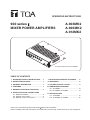
Thank you for purchasing TOA's 900 Series Mixer Power Amplier.
Please carefully follow the instructions in this manual to ensure long, trouble-free use of your equipment.
This gure represents the A-903MK2.
1. IMPORTANT SAFETY INSTRUCTIONS ..... 2
2. SAFETY PRECAUTIONS ............................ 3
3. GENERAL DESCRIPTION .......................... 5
4. FEATURES .................................................. 5
5. NOMENCLATURE AND FUNCTIONS ........ 6
6. INSTALLATION AND CONNECTIONS
6.1. Module Installation ................................ 8
6.2. Speaker Connections ............................ 9
6.3. Remote Control Connections .............. 11
7.
RACK MOUNTING BRACKET ATTACHMENT
... 12
8. OPERATION .............................................. 13
9. VOLUME CONTROL COVER ................... 13
10. DIMENSIONAL DIAGRAMS
10.1. A-903MK2 ......................................... 14
10.2. A-906MK2, A-912MK2 ...................... 14
11. SPECIFICATIONS
11.1. A-903MK2 ......................................... 15
11.2. A-906MK2, A-912MK2 ....................... 16
TABLE OF CONTENTS

2
1. IMPORTANT SAFETY INSTRUCTIONS
• Read these instructions.
• Keep these instructions.
• Heed all warnings.
• Follow all instructions.
• Do not use this apparatus near water.
• Clean only with dry cloth.
• Do not block any ventilation openings. Install in accordance with the manufacturer's instructions.
• Do not install near any heat sources such as radiators, heat registers, stoves, or other apparatus (including
amplifiers) that produce heat.
• Do not defeat the safety purpose of the polarized or grounding-type plug. A polarized plug has two blades
with one wider than the other. A grounding type plug has two blades and a third grounding prong. The wide
blade or the third prong are provided for your safety. If the provided plug does not fit into your outlet, consult
an electrician for replacement of the obsolete outlet.
• Protect the power cord from being walked on or pinched particularly at plugs, convenience receptacles, and
the point where they exit from the apparatus.
• Only use attachments/accessories specified by the manufacturer.
• Use only with the cart, stand, tripod, bracket, or table specified by the manufacturer,
or sold with the apparatus. When a cart is used, use caution when moving the
cart/apparatus combination to avoid injury from tip-over.
• Unplug this apparatus during lightning storms or when unused for long periods of time.
• Refer all servicing to qualified service personnel. Servicing is required when the apparatus has been
damaged in any way, such as power-supply cord or plug is damaged, liquid has been spilled or objects have
fallen into the apparatus, the apparatus has been exposed to rain or moisture, does not operate normally, or
has been dropped.
INSTRUCTIONS ESSENTIELLES POUR LA SÉCURITÉ
• Lire ces instructions.
• Conserver ces instructions pour référence ultérieure.
• Respecter tous les avertissements.
• Suivre toutes les instructions.
• Ne pas utiliser cet appareil à proximité d'eau.
• Nettoyer uniquement à l'aide d'un chiffon sec.
• Ne pas obstruer les orifices de ventilation. Installer conformément aux instructions du fabricant.
• Ne pas installer à proximité de sources de chaleur telles que des radiateurs, des registres thermiques, des
chaudières ou d'autres appareils (notamment des amplificateurs) produisant de la chaleur.
• Ne pas contourner la fonction de sécurité de la fiche polarisée ou de mise à la terre. Une fiche polarisée est
équipée de deux broches, dont l'une est plus large que l'autre. Une fiche de mise à la terre est équipée de
deux broches et d'une troisième pour la mise à la terre. Cette dernière, la plus large, est prévue à des fins
de sécurité. Si la fiche fournie ne peut être insérée dans la prise électrique souhaitée, consulter un
électricien pour faire remplacer cette dernière.
• Protéger le cordon d'alimentation pour éviter qu'il ne soit piétiné ou pincé, notamment au niveau des fiches,
des prises de courant ou de son point de sortie de l'appareil.
• Utiliser uniquement les accessoires spécifiés par le fabricant.
• Utiliser uniquement avec le chariot, support, trépied, la patte de montage ou la table
spécifiés par le fabricant ou vendus avec l'appareil. En cas d'utilisation d'un chariot,
manipuler la combinaison chariot/appareil pour éviter les blessures dues à un
renversement.
• Débrancher cet appareil pendant les orages ainsi que lorsqu'il reste inutilisé pendant une période prolongée.
• La maintenance de l'appareil doit être confiée à un technicien après-vente qualifié. Une maintenance s'avère
nécessaire si l'appareil est endommagé (au niveau du cordon d'alimentation ou de la fiche), a été mouillé
par un liquide, un objet est tombé à l'intérieur, s'il a été exposé à la pluie ou l'humidité, s'il ne fonctionne pas
normalement ou s'il est tombé.

3
2. SAFETY PRECAUTIONS
• Before installation or use, be sure to carefully read all the instructions in this section for correct and safe
operation.
• Be sure to follow all the precautionary instructions in this section, which contain important warnings and/or
cautions regarding safety.
• After reading, keep this manual handy for future reference.
Safety Symbol and Message Conventions
Safety symbols and messages described below are used in this manual to prevent bodily injury and property
damage which could result from mishandling. Before operating your product, read this manual first and
understand the safety symbols and messages so you are thoroughly aware of the potential safety hazards.
When Installing the Unit
• Do not expose the unit to rain or an environment where it may be splashed by water or other liquids, as
doing so may result in fire or electric shock.
• Use the unit only with the voltage specified on the unit. Using a voltage higher than that which is specified
may result in fire or electric shock.
• Do not cut, kink, otherwise damage nor modify the power supply cord. In addition, avoid using the power
cord in close proximity to heaters, and never place heavy objects -- including the unit itself -- on the power
cord, as doing so may result in fire or electric shock.
• Be sure to replace the unit's terminal cover after connection completion. Because high voltage is applied to
the speaker output terminals, never touch these terminals to avoid electric shock.
• Avoid installing or mounting the unit in unstable locations, such as on a rickety table or a slanted surface.
Doing so may result in the unit falling down and causing personal injury and/or property damage.
• External wiring connected to the terminals marked with requires installation by an instructed person.
• The apparatus shall be connected to a mains socket outlet with a protective earthing connection.
• L'appareil doit être branché à une prise d'alimentation avec mise à la terre de protection.
• The socket-outlet shall be installed near the equipment and the plug shall be easily accessible.
• Use the optional Rack mounting bracket MB-25B when mounting the unit in an equipment rack. Remove
four M4 x 8 screws on both sides of the unit, and mount the bracket there using the M4 x 16 screws
(supplied with the bracket) instead.
When the Unit is in Use
• Should the following irregularity be found during use, immediately switch off the power, disconnect the power
supply plug from the AC outlet and contact your nearest TOA dealer. Make no further attempt to operate the
unit in this condition as this may cause fire or electric shock.
· If you detect smoke or a strange smell coming from the unit
· If water or any metallic object gets into the unit
· If the unit falls, or the unit case breaks
· If the power supply cord is damaged (exposure of the core, disconnection, etc.)
· If it is malfunctioning (no tone sounds.)
• To prevent a fire or electric shock, never open nor remove the unit case as there are high voltage
components inside the unit. Refer all servicing to your nearest TOA dealer.
• Do not place cups, bowls, or other containers of liquid or metallic objects on top of the unit. If they
accidentally spill into the unit, this may cause a fire or electric shock.
• Do not insert nor drop metallic objects or flammable materials in the ventilation slots of the unit's cover, as
this may result in fire or electric shock.
Indicates a potentially hazardous situation which, if mishandled,
could result in death or serious personal injury.
WARNING
The exclamation point within an equilateral triangle is intended to alert the user to the presence of
important operation and maintenance (servicing) instruction in the literature accompanying the
appliance.
Le point d'exclamation à l'intérieur d'un triangle équilatéral avertit l'utilisateur de l'existence
d'instructions d'utilisation et d'entretien (réparation) dans la documentation fournie avec l'appareil.

4
When Installing the Unit
• Never plug in nor remove the power supply plug with wet hands, as doing so may cause electric shock.
• When unplugging the power supply cord, be sure to grasp the power supply plug; never pull on the cord
itself. Operating the unit with a damaged power supply cord may cause a fire or electric shock.
• When moving the unit, be sure to remove its power supply cord from the wall outlet. Moving the unit with the
power cord connected to the outlet may cause damage to the power cord, resulting in fire or electric shock.
When removing the power cord, be sure to hold its plug to pull.
• Do not block the ventilation slots in the unit's cover. Doing so may cause heat to build up inside the unit and
result in fire.
• Avoid installing the unit in humid or dusty locations, in locations exposed to the direct sunlight, near the
heaters, or in locations generating sooty smoke or steam as doing otherwise may result in fire or electric
shock.
• To avoid electric shocks, be sure to unplug the unit's power supply cord when connecting speakers.
• Be sure to follow the instructions below when rack-mounting the unit. Failure to do so may cause a fire or
personal injury.
· Install the equipment rack on a stable, hard floor. Fix it with anchor bolts or take other arrangements to
prevent it from falling down.
· When connecting the unit's power cord to an AC outlet, use the AC outlet with current capacity allowable to
the unit.
· No rack-mounting screws are supplied with the unit. Separately prepare the appropriate screws for the
rack.
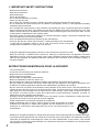
• Keep the amplifier over 10 cm (3.94") away
from objects that may obstruct air flow to
prevent the unit's internal temperature rise.
When the Unit is in Use
• Do not place heavy objects on the unit as this may cause it to fall or break which may result in personal
injury and/or property damage. In addition, the object itself may fall off and cause injury and/or damage.
• Make sure that the volume control is set to minimum position before power is switched on. Loud noise
produced at high volume when power is switched on can impair hearing.
• Do not operate the unit for an extended period of time with the sound distorting. This is an indication of a
malfunction, which in turn can cause heat to generate and result in a fire.
• If dust accumulates on the power supply plug or in the wall AC outlet, a fire may result. Clean it periodically.
In addition, insert the plug in the wall outlet securely.
• Switch off the power, and unplug the power supply plug from the AC outlet for safety purposes when
cleaning or leaving the unit unused for 10 days or more. Doing otherwise may cause a fire or electric shock.
Indicates a potentially hazardous situation which, if mishandled, could
result in moderate or minor personal injury, and/or property damage.
L'appareil ne doit pas être exposé aux éclaboussures ou écoulements et tous objets remplis de liquide, tels
que vases, ne doivent pas être sur l’appareil.
The lighting flash with arrowhead symbol, within an equilateral triangle, is intended to alert the user
to the presence of uninsulated "dangerous voltage" within the product's enclosure that may be of
sufficient magnitude to constitute a risk of electric shock to persons.
L'éclair accompagné d'un symbole représentant une pointe de flèche à l'intérieur d'un triangle
équilatéral avertit l'utilisateur de la présence d'une "tension dangereuse" à l'intérieur de l'enceinte
du téléviseur, dont la magnitude peut être suffisante pour constituer un risque de choc électrique
pour les personnes.
CAUTION
ATTENTION
Over 10 cm (3.94") Over 10 cm (3.94")
Over 10 cm
(3.94")

5
3. GENERAL DESCRIPTION
TOA's A-903MK2, A-906MK2, and A-912MK2 Mixer Power Amplifiers feature 8 input slots that permit the use
of various optional plug-in modules. The most appropriate plug-in modules can be selected depending on
applications. The Mixer Power Amplifiers are identical except for output power: A-903MK2 (30 W), A-906MK2
(60 W), and A-912MK2 (120 W).
The speaker output terminals are designed to match 25 V or 70 V line, or 4 Ω or 8 Ω speaker systems.
Each Mixer Power Amplifier can be mounted in an EIA equipment rack with the addition of the optional MB-
25B Rack Mounting Bracket. The optional perforated panel PF-511 provides suitable ventilation, finished in
black color to match the Mixer Power Amplifiers.
4. FEATURES
• Plug-in modular construction
• A wide frequency response of 20 to 20,000 Hz (±1 dB)
• Low distortion and low noise
• Remote volume control connection
• Independent bass and treble controls
• Bridging Input/Output Jack for easy system expansion
• Built-in protection circuitry
• Usable a wide range of plug-in optional modules

AUX
OUT
PRE
AMP
IN
PRE
AMP
OUT
REMT
VOL
MUTE
1
MUTE
2
BRG
IN/
OUT
70V
25V
COM
DIRECT
4Ω 8Ω
AUX
OUT
PRE
AMP
IN
PRE
AMP
OUT
REMT
VOL
MUTE
1
MUTE
2
BRG
IN/
OUT
70V
25V
COM
DIRECT
4Ω 8Ω
13 14 15
17
18
19
20
21
22
23
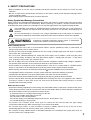
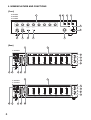
A-906MK2
A-912MK2
13 14 15 16
16
17
18
19
20
21
22
23
A-903MK2
[Rear]
6
SIGNAL NORMAL
PROTECT
PEAK
POWER
ON
OFF
MASTER
INPUT 8INPUT 7INPUT 6INPUT 5INPUT 4INPUT 3INPUT 2INPUT 1
TREBLE TONE DEFEAT
OFF ON
BASS LOW CUT
OFF ON
2
1
34567
8 9
10 11 12
A-903MK2
A-906MK2
A-912MK2
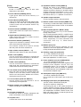
5. NOMENCLATURE AND FUNCTIONS
[Front]

7
[Front]
1. Power switch [ ON / OFF]
Power is switched on and off with each
depression of this switch.
2. Power indicator [POWER] (Green)
Lights green when the Power switch (1) is
switched on.
3. Peak indicator [PEAK] (Red)
Lights red if input signals approach clipping level.
If steady lit, turn down the corresponding Input
volume control until the indicator flashes only
intermittently.
4. Normal indicator [NORMAL] (Yellow)
Lights yellow when the output sound volume is
appropriate.
5. Signal Indicator [SIGNAL] (Green)
Lights green when sound is output from the
speaker output terminals.
6. Protection indicator [PROTECT]
Lights red if the built-in protection circuit works
due to excessive input signal level.
This indicator remains lit for about 5 seconds
after the power has been switched on.
7. Input volume controls [INPUT 1 — 8]
Adjust the input volume of each input channel.
8. Bass control [BASS]
Turn the control knob clockwise to increase the
bass level and counterclockwise to decrease it.
Bass level is flat at the center position.
9. Treble control [TREBLE]
Turn the control knob clockwise to increase the
treble level and counterclockwise to decrease it.
Treble level is flat at the center position.
10. Tone defeat switch [TONE DEFEAT ON/OFF]
Bass and treble controls are enabled when this
switch is set to the OFF position. Setting this
switch to the ON position disables the controls,
causing the tones to be flat.
11. Low-cut switch [LOW CUT ON/OFF]
Set this switch to the ON position to cut off
unnecessary low frequencies.
12. Master volume control [MASTER]
Adjusts overall gain of all input channels.
[Rear]
13. AC outlet (unswitched)
Provides AC power to auxiliary equipment with
power consumption of less than 500 W.
14. AC power cord
Connect this cord to an AC wall outlet.
15. Impedance selector switch [DIRECT]
Placing the switch in the "DIRECT" position
enables only unbalanced low-impedance
speaker connection. Placing it in another position
enables transformer-balanced 25 V, 70 V, or low-
impedance speaker connection. For the use of
this switch, refer to p. 9, "Speaker Connections."
16. Speaker output terminals
Connect speaker cables to these terminals.
17. Remote volume control terminal [REMT VOL]
Connecting a 10 kΩ linear taper potentiometer to
this terminal allows remote control of the Master
volume control.
18. Mute terminals [MUTE 1, MUTE 2, GND]
Activates mute control only to the modules
having mute function.
Short-circuiting between MUTE 1 or MUTE 2 and
GND terminals mutes the modules set for "mute
receive" function activated on MUTE 1 or MUTE
2 bus, respectively. For more information and
connection, refer to p. 11, "Mute Control
Connection."
19. Module input ports
Accept 900 series plug-in modules. For the
selection of the most appropriate modules, refer
to Plug-in Module Instruction manual.
20. Auxiliary output jack [AUX OUT]
1 V, 10 kΩ, unbalanced, RCA jack.
Connect to the booster amplifier or a recorder
with input impedance of 10 kΩ or more.
21. Power amplifier input jack (PWR AMP IN)
1 V, 10 kΩ, unbalanced, RCA jack.
Inserting a RCA plug into this jack separates the
internal power amplifier section from the
preamplifier section. As a normal use, a signal
processing device such as a limiter or equalizer
is inserted between the Preamplifier output (22)
and the Power amplifier input.
22. Preamplifier output jack [PRE OUT]
1 V, 600 Ω, unbalanced, RCA jack.
For a normal use of this output, refer to item (21)
above.
23. Bridging input/output jack [BRG IN/OUT]
100 mV, 3.3 kΩ, unbalanced, RCA jack.
This jack is used as a mixing bus.
Connecting this jack to the similar terminal of
another amplifier achieves mixing (expansion of
input sources). The signals appearing at the jack
are independent of Master volume control, and
Bass and Treble controls, so that the jack can be
used as recording output.

8
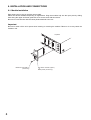
6. INSTALLATION AND CONNECTIONS
6.1. Module Installation
Eight input ports for plug-in modules are provided.
Select the desired modules depending on applications. Plug the modules fully into the input ports by sliding
them along the upper and lower guide rails, then secure each with two screws.
Be sure to cover idle slots with the blank panels attached to the unit.
Important
Be sure to switch off the unit's power when inserting or removing the module. Failure to do so may cause the
module to fail.
A
U
X
O
U
T
P
R
E
A
M
P
I
N
PR
E
AM
P
O
U
T
B
R
G
I
N/
O
U
T
Amplifier
900 Series module (option)
or
Blank panel (accessory)
Machine screw M3 x 8
(accessory)

9
DIRECT
4Ω 8Ω
70V
25V
COM
4 Ω
25 V line (21 Ω)
70 V line (167 Ω)
Impedance selector switch
1, 3
2
6.2. Speaker Connections
The unit has 25 V and 70 V outputs for constant voltage speaker system and low impedance output for 4 Ω or
8 Ω speaker loads.
Two types of speaker output are available: transformer-balanced output and unbalanced direct output, which
can be selected by the Impedance selector switch.
Connect the speaker system to only one of the speaker outputs. Class 2 wiring may be used.
The speaker connection method differs with amplifier models and their applications.
Refer to the following connection diagrams described for each model. Impedances indicated in the diagram
mean total speaker load impedance.
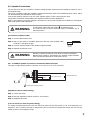
6.2.1. A-903MK2: Speaker connection to transformer-balanced output
Step 1. Unscrew the terminal cover.
Step 2. Strip 10 mm (0.39") of insulative jacket from the end of the speaker cable,
as shown in the figure at right.
Step 3. Connect speaker cables to the speaker output terminals.
Step 4. Replace the terminal cover.
10 mm
(0.39”)
[Connection of speaker cable]
[Impedance selector switch setting]
Step 1. Loosen the screw.
Step 2. Shift the impedance selector switch to "4 Ω" position.
Step 3. Retighten the screw.
[Low-cut switch (on the front panel) setting]
It is highly recommended that the low-cut switch be placed in the ON position to cut off unnecessary low
frequency. This is because the built-in transformer cannot produce low frequencies though the unit has flat
response even in low-frequency range.
This type of output allows speaker connection to one of 4 Ω, 25 V, or 70 V terminal.
Be sure to replace the terminal cover after connection completion.
Because high voltage is generated at the speaker output terminals,
never touch these terminals to avoid electric shock.
WARNING
The terminals marked with the symbol are hazardous live.
The external wiring to these terminals requires installation by an
instructed person.
WARNING

10
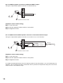
6.2.2. A-903MK2: Speaker connection to unbalanced DIRECT output
DIRECT
4Ω 8Ω
70V
25V
COM
8 Ω
1, 3
Impedance selector switch
2
[Impedance selector switch setting]
Step 1. Loosen the screw.
Step 2. Shift the impedance selector switch to "8 Ω" position.
Step 3. Retighten the screw.
This type of output allows speaker connection to 8 Ω terminal only.
6.2.3. A-906MK2 and A-912MK2: Speaker connection to transformer-balanced output
DIRECT
4Ω 8Ω
70V
25V
COM
8 Ω
25 V line
A-906MK2: 10.4 Ω
A-912MK2: 5.2 Ω
1, 3
70 V line
A-906MK2: 83 Ω
A-912MK2: 41 Ω
Impedance selector switch
2
[Impedance selector switch setting]
Step 1. Loosen the screw.
Step 2. Shift the impedance selector switch to "8 Ω" position.
Step 3. Retighten the screw.
It is highly recommended that the low-cut switch be placed in the ON position to cut off unnecessary low
frequency. This is because the built-in transformer cannot produce low frequencies though the unit has flat
response even in low-frequency range.
This type of output allows speaker connection to one of 8 Ω, 25 V, or 70 V terminal.

11
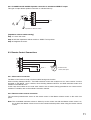
6.2.4. A-906MK2 and A-912MK2: Speaker connection to unbalanced DIRECT output
DIRECT
4Ω 8Ω
70V
25V
COM
4 Ω
1, 3
Impedance selector switch
2
REMT
VOL
MUTE
1
MUTE
2
GND
Potentiometer
10 kΩ, liner taper
MUTE 1MUTE 2
[Impedance selector switch setting]
Step 1. Loosen the screw.
Step 2. Shift the impedance selector switch to "DIRECT 4 Ω" position.
Step 3. Retighten the screw.
6.3.1. Mute control connection
The Mute control works to mute only the modules having mute function.
Short-circuiting between MUTE 1 and GND terminals mutes the modules set for "mute receive" function
activated on the MUTE 1 bus. Likewise, short-circuiting between MUTE 2 and GND terminals mutes such
modules on the MUTE 2 bus.
In this case, the modules set for "mute send" function are not muted, having precedence over "mute receive"
modules. For details, refer to the module's instruction manual.
6.3.2. Remote volume control connection
The connected potentiometer serves as the remote control of the Master volume control on the unit's front
panel.
Note: The controllable maximum volume is limited up to the volume set with the Master volume control. So,
do not place the Master volume control in the counterclockwise position when using the remote volume
control.
This type of output allows speaker connection to 4 Ω terminal only.
6.3. Remote Control Connections

12
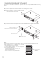
7. RACK MOUNTING BRACKET ATTACHMENT
The unit can be mounted in a standard 19" equipment rack using the optional MB-25B Rack mounting
bracket.
Notes
• Rack mounting screws are not supplied with the unit. Use the screws that are appropriate for the rack.
• When mounting the unit in an equipment rack, the inside
of the rack must be sufficiently ventilated.
To achieve sufficient ventilation, also mount the optional
PF-511 Perforated Panel (1U*):
(1) at the top and the bottom of the rack, and
(2) above and below the unit.
* 1U size = 44.5 mm or 1.75" (reference size)
Amplifier
Amplifier
Amplifier
Perforated Panel
PF-511
(1-unit size)
T
O
N
E
D
E
F
E
A
T
O
F
F
O
N
L
O
W
C
U
T
O
F
F
O
N
S
IG
N
A
L
N
O
R
M
A
L
P
R
O
T
E
C
T
O
N
O
F
F
P
E
A
K
P
O
W
E
R
M
A
S
T
E
R
I
N
P
U
T
8
I
N
P
U
T
7
I
N
P
U
T
6
I
N
P
U
T
5
I
N
P
U
T
4
I
N
P
U
T
3
I
N
P
U
T
2
T
R
E
B
LE
I
N
P
U
T
1
B
A
S
S
T
O
N
E
D
E
F
E
AT
O
F
F
O
N
L
O
W
C
U
T
O
F
F
O
N
S
IG
N
A
L
N
O
R
M
A
L
P
R
O
T
E
C
T
O
N
O
F
F
P
E
A
K
P
O
W
E
R
M
A
S
T
E
R
I
N
P
U
T
8
I
N
P
U
T
7
I
N
P
U
T
6
I
N
P
U
T
5
I
N
P
U
T
4
I
N
P
U
T
3
I
N
P
U
T
2
T
R
E
B
L
E
I
N
P
U
T
1
B
A
S
S
Rack mounting screw
Machine screw M4 x 16
(supplied with the rack mounting bracket)
Rack mounting bracket
MB-25B
Step 1. Remove 4 plastic feet on the bottom surface when mounting the unit in a rack.
Step 2. Remove four M4 x 8 screws on both sides of the unit.
The removed screws are not used.
Step 3. Attach the brackets to the amplifier using four M4 x 16 Machine screws supplied with the bracket.

13
Master volume control knob
Volume control cover YA-920
(accessory)
9. VOLUME CONTROL COVER
To prevent the accidental change of the settings of the Input and Master volume controls, remove the knobs
after setting them to the desired position and attach the optional cover YA-920 instead.
8. OPERATION
Step 1. Press the power switch to turn on the power.
The power indicator lights green.
The amplifier comes into operation about 5 seconds after the power has been switched on.
Step 2. Adjust the individual input and master volume controls for the optimum level. Turn the knobs
clockwise to increase the output level and counterclockwise to decrease it. For normal music playing
or announcement, adjust the input level so that the Normal Indicator intermittently lights. Sound
quality is downgraded when the Peak Indicator remains lit.
Step 3. Adjust the Bass and Treble controls.
Set the Tone Defeat Switch to the OFF position to activate the Bass and Treble controls. The Bass
control boosts low frequencies in clockwise (cw) position and cuts in counterclockwise (ccw) position
while the Treble control boosts high frequencies in cw position and cuts in ccw position. The center
position of both controls provides flat frequency response.
When tone controls are not necessary, set the Tone Defeat Switch to the ON position.

SIGNAL NORMAL
PROTECT
PEAK
POWER
ON
OFF
MASTER
INPUT 8INPUT 7INPUT 6INPUT 5INPUT 4INPUT 3INPUT 2INPUT 1
TREBLE TONE DEFEAT
OFF ON
BASS LOW CUT
OFF ON
INPUT 8 INPUT 7 INPUT 6 INPUT 5 INPUT 4 INPUT 3 INPUT 2 INPUT 1
SIGNAL NORMAL
PROTECT
PEAK
POWER
ON
OFF
MASTER
INPUT 8INPUT 7INPUT 6INPUT 5INPUT 4INPUT 3INPUT 2INPUT 1
TREBLE TONE DEFEAT
OFF ON
BASS LOW CUT
OFF ON
INPUT 8 INPUT 7 INPUT 6 INPUT 5 INPUT 4 INPUT 3 INPUT 2 INPUT 1
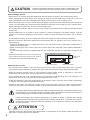
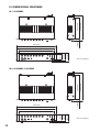
280 (11.02)17 (0.67)
318 (12.52)
Unit: mm (inches)
Unit: mm (inches)
76.2 (3)
88.4 (3.48)
99.1 (3.9)
466 (18.35)
420 (16.54)
482.6 (19)
466 (18.35)
420 (16.54)
482.6 (19)
320 (12.6)17 (0.67)
358 (14.09)
76.2 (3)
88.4 (3.48)
99.1 (3.9)
14
10. DIMENSIONAL DIAGRAMS
10.1. A-903MK2
10.2. A-906MK2, A-912MK2

15
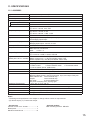
11. SPECIFICATIONS
• Accessories
Volume control cover YA-920 .................... 4
Blank panel ................................................ 7
Machine screw M3 x 8 ............................. 14
• Optional product
Rack mounting bracket: MB-25B
11.1. A-903MK2
Type 8-channel mixer power amplier
Power Source 120 V AC, 60 Hz
Rated Output 30 W RMS
Power Consumption
Rated output 60 W
Based on cUL standards 40 W
Power Bandwidth (D): 20 Hz – 20 kHz, 0.5% THD
(T): 50 Hz – 20 kHz, 0.5% THD
Frequency Response (D): 20 Hz – 20 kHz, ±1 dB
(T): 20 Hz – 15 kHz, ±1 dB
(T): 20 Hz – 20 kHz, +1 dB, –3 dB
Total Harmonic Distortion 0.02% at 1 kHz, rated output
Input Eight input ports: each port accepts any input module.
One bridging input/output
Input Sensitivity/Impedance Input port #1 to #8: 100 mV / 10 kΩ
Bridging input/output: 100 mV / 3.3 kΩ
Preamp OUT/Power amp IN 1000 mV into 600 Ω / 1000 mV, 10 kΩ
Output Main (T): 4 Ω, 25 V and 70 V, balanced
Main (D): 8 Ω, unbalanced
AUX: 10 kΩ, 1 V
Output Regulation (1 kHz) (D): Less than 0.5 dB, no load to full load
(T): Less than 1.0 dB, no load to full load
Signal to Noise Ratio
(Band pass: 20 Hz – 20 kHz)
Master volume min.: 90 dB (Tone defeat switch: ON)
Master volume max.: 77 dB (Tone defeat switch: ON)
Power amplier only: 105 dB (Tone defeat switch: ON)
Tone Control Bass: ±10 dB at 100 Hz, Treble: ±10 dB at 10 kHz
Control 8 Input gain control 1 Master gain control 1 Bass control
1 Treble control 1 Power ON/OFF switch 1 Tone defeat switch
1 Low-cut switch (60 Hz, 6 dB/octave)
Indicator 1 Power LED, 1 Protect LED, 1 Signal LED, 1 Normal LED, 1 Peak LED
Protection Self-protection, with AC fuse (inside)
Connector Input 1 to 8: card-edge connector
Bridging, Mixer preamp. output, Power amp. input, Aux output: RCA jack
Mute, Remote VR: screw terminal strip
Output: screw terminal strip
AC outlet: 3-pin grounding type
AC power cord/plug: SJT, 3-prong type
Operating Temperature –10 to +60 °C (12 to 140 °F)
Other Feature Output disconnected for approx. 5 seconds after switching power on.
Color Black
Dimensions 420 (w) x 99.1 (h) x 318 (d) mm (16.54" x 3.9" x 12.52")
Weight 7.8 kg (17.2 lb)
Notes
• The design and specications are subject to change without notice for improvement.
• (D): Direct output, (T): Transformer output

URL: https://www.toa.jp/
133-02-00085-01
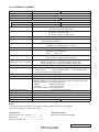
• Accessories
Volume control cover YA-920 .................... 4
Blank panel ................................................ 7
Machine screw M3 x 8 ............................. 14
• Optional product
Rack mounting bracket: MB-25B
11.2. A-906MK2, A-912MK2
Model No. A-906MK2 A-912MK2
Type 8-channel mixer power amplier
Power Source 120 V AC, 60 Hz
Rated Output 60 W RMS 120 W RMS
Power Consumption
Rated output 100 W 180 W
Based on cUL standards 70 W 105 W
Power Bandwidth (D): 20 Hz – 20 kHz, 0.5% THD
(T): 50 Hz – 20 kHz, 0.5% THD
Frequency Response (D): 20 Hz – 20 kHz, ±1 dB
(T): 20 Hz – 15 kHz, ±1 dB
(T): 20 Hz – 20 kHz, +1 dB, –3 dB
Total Harmonic Distortion 0.02% at 1 kHz, rated output
Input Eight input ports: each port accepts any input module.
One bridging input/output
Input Sensitivity/Impedance Input port #1 to #8: 100 mV / 10 kΩ
Bridging input/output: 100 mV / 3.3 kΩ
Preamp OUT/Power amp IN 1000 mV into 600 Ω / 1000 mV, 10 kΩ
Output Main (T): 8 Ω, 25 V and 70 V, balanced
Main (D): 4 Ω, unbalanced
AUX: 10 kΩ, 1 V
Output Regulation (1 kHz) (D): Less than 0.5 dB, no load to full load
(T): Less than 1.0 dB, no load to full load
Signal to Noise Ratio
(Band pass: 20 Hz – 20 kHz)
Master volume min.: 90 dB (Tone defeat switch: ON)
Master volume max.: 77 dB (Tone defeat switch: ON)
Power amplier only: 105 dB (Tone defeat switch: ON)
Tone Control Bass: ±10 dB at 100 Hz, Treble: ±10 dB at 10 kHz
Control 8 Input gain control 1 Master gain control 1 Bass control
1 Treble control 1 Power ON/OFF switch 1 Tone defeat switch
1 Low-cut switch (60 Hz, 6 dB/octave)
Indicator 1 Power LED, 1 Protect LED, 1 Signal LED, 1 Normal LED, 1 Peak LED
Protection Self-protection, with AC fuse (inside)
Connector Input 1 to 8: card-edge connector
Bridging, Mixer preamp. output, Power amp. input, Aux output: RCA jack
Mute, Remote VR: screw terminal strip
Output: screw terminal strip
AC outlet: 3-pin grounding type
AC power cord/plug: SJT, 3-prong type
Operating Temperature –10 to +60 °C (12 to 140 °F)
Other Feature Output disconnected for approx. 5 seconds after switching power on.
Color Black
Dimensions 420 (w) x 99.1 (h) x 358 (d) mm (16.54" x 3.9" x 14.09")
Weight 9.6 kg (21.16 lb) 12.7 kg (28 lb)
Notes
• The design and specications are subject to change without notice for improvement.
• (D): Direct output, (T): Transformer output
-
 1
1
-
 2
2
-
 3
3
-
 4
4
-
 5
5
-
 6
6
-
 7
7
-
 8
8
-
 9
9
-
 10
10
-
 11
11
-
 12
12
-
 13
13
-
 14
14
-
 15
15
-
 16
16


TOA A-906MK2 Manuel utilisateur
- Catégorie
- Amplificateurs audio
- Taper
- Manuel utilisateur
- Ce manuel convient également à
dans d''autres langues
- English: TOA A-906MK2 User manual
Documents connexes
-
TOA P-924MK2 UL Manuel utilisateur
-
-
TOA A-912MK2 HH Manuel utilisateur
-
-
TOA DA-250D CU Manuel utilisateur
-
Optimus A-5006 Manuel utilisateur
-
-
Optimus A-2060CE Fiche technique
-
-
TOA BG-2480D Manuel utilisateur