STIEBEL ELTRON CWM 500-3000 P | CWM 500-3000 U Operation Instruction
- Taper
- Operation Instruction

OPERATION AND INSTALLATION
UTILISATION ET INSTALLATION
BEDIENING EN INSTALLATIE
OBSLUHA A INSTALACE
OBSLUHA A INŠTALÁCIA
OBSŁUGA I INSTALACJA
KEZELÉS ÉS TELEPÍTÉS
ЭКСПЛУАТАЦИЯ И УСТАНОВКА
Wall mounted convector heater | Convecteur mural | Wandconvector | Nástěnný
konvektor | Nástenný konvektor | Konwektor wiszący | Fali konvektor | Настенный
конвектор
» CWM 500 P
» CWM 750 P
» CWM 1000 P
» CWM 1500 P
» CWM 2000 P
» CWM 2500 P
» CWM 3000 P
» CWM 500 U
» CWM 750 U
» CWM 1000 U
» CWM 1500 U
» CWM 2000 U
» CWM 2500 U
» CWM 3000 U

2 | CWM P | CWM U www.stiebel-eltron.com
CONTENTS | SPECIAL INFORMATION
SPECIAL INFORMATION
- Keep children under the age of3 away from
the appliance if constant supervision cannot
be guaranteed.
- Children from the age of 3 to 7 may switch
the appliance on and off, provided they are
supervised or have been instructed in the safe
operation of the appliance and understand
any risks that may result. This is subject to the
appliance having been installed as described.
Children from the age of 3 to 7 must not plug
the power cable into its socket or regulate the
appliance.
- The appliance may be used by children aged8
and older and persons with reduced physical,
sensory or mental capabilities or a lack of ex-
perience and know-how, provided that they
are supervised or they have been instructed
on how to use the appliance safely and have
understood the potential risks.
- Children must never play with the appliance.
Children must never clean the appliance or
perform user maintenance unless they are
supervised.
- Parts of the appliance can get very hot and
may cause burns. Particular caution is ad-
vised when children or vulnerable persons are
present.
- In order to avoid overheating, do not cover
the heater.
- Never install the appliance directly below a
wall socket.
- In the case of a permanent connection, the
appliance must be able to be separated from
the power supply by an isolator that discon-
nects all poles with at least 3mm contact
separation.
SPECIAL INFORMATION
OPERATION
1. General information �����������������������������������������3
1.1 Safety instructions ����������������������������������������������� 3
1.2 Other symbols in this documentation ����������������������� 3
1.3 Information on the appliance ��������������������������������� 3
1.4 Units of measurement ������������������������������������������ 3
2. Safety ���������������������������������������������������������� 3
2.1 Intended use ������������������������������������������������������ 3
2.2 General safety instructions ������������������������������������ 4
2.3 Test symbols ������������������������������������������������������ 4
3. Appliance description ���������������������������������������4
4. Operation �����������������������������������������������������4
4.1 Programming unit ����������������������������������������������� 5
4.2 Switching the appliance on and off �������������������������� 5
4.3 Standby mode ���������������������������������������������������� 5
5. Settings �������������������������������������������������������6
5.1 Standard display ������������������������������������������������� 6
5.2 Standard menu ��������������������������������������������������� 6
5.3 Configuration menu ��������������������������������������������� 6
6. Cleaning, care and maintenance ���������������������������8
7. Troubleshooting ����������������������������������������������8
INSTALLATION
8. Safety ���������������������������������������������������������� 8
8.1 General safety instructions ������������������������������������ 8
8.2 Instructions, standards and regulations �������������������� 8
9. Appliance description ���������������������������������������8
9.1 Standard delivery ������������������������������������������������ 8
10. Installation ����������������������������������������������������9
10.1 Minimum clearances �������������������������������������������� 9
10.2 Installing the wall mounting bracket ������������������������ 9
10.3 Appliance installation ������������������������������������������� 9
10.4 Removing the appliance ���������������������������������������10
10.5 Electrical connection ������������������������������������������� 10
11. Commissioning ��������������������������������������������� 10
12. Troubleshooting �������������������������������������������� 10
13. Appliance handover ���������������������������������������� 10
14. Specification ������������������������������������������������ 11
14.1 Dimensions and connections ��������������������������������� 11
14.2 Energy consumption data ������������������������������������� 11
14.3 Data table �������������������������������������������������������� 12
GUARANTEE
ENVIRONMENT AND RECYCLING

OPERATION
General information
ENGLISH
www.stiebel-eltron.com CWM P | CWM U | 3
- The power cable must only be replaced (for
example if damaged) by a qualified contrac-
tor authorised by the manufacturer, using an
original spare part.
- Secure the appliance as described in chapter
"Installation/ Installation".
OPERATION
1. General information
The chapters "Special information" and "Operation" are intended
for both users and qualified contractors.
The chapter "Installation" is intended for qualified contractors.
Note
Read these instructions carefully before using the appli-
ance and retain them for future reference.
Pass on the instructions to a new user if required.
1.1 Safety instructions
1.1.1 Structure of safety instructions
KEYWORD Type of risk
Here, possible consequences are listed that may result
from failure to observe the safety instructions.
Steps to prevent the risk are listed.
1.1.2 Symbols, type of risk
Symbol Type of risk
Injury
Electrocution
Burns
(burns, scalding)
1.1.3 Keywords
KEYWORD Meaning
DANGER Failure to observe this information will result in serious
injury or death.
WARNING Failure to observe this information may result in serious
injury or death.
CAUTION Failure to observe this information may result in non-seri-
ous or minor injury.
1.2 Other symbols in this documentation
Note
General information is identified by the adjacent symbol.
Read these texts carefully.
Symbol Meaning
Material losses
(appliance damage, consequential losses and environmen-
tal pollution)
Appliance disposal
This symbol indicates that you have to do something. The ac-
tion you need to take is described step by step.
1.3 Information on the appliance
Symbol Meaning
Never cover the appliance
1.4 Units of measurement
Note
All measurements are given in mm unless stated oth-
erwise.
2. Safety
2.1 Intended use
This appliance is designed to heat living areas.
The appliance is intended for domestic use. It can be used safely
by untrained persons. The appliance can also be used in a non-do-
mestic environment, e.g. in a small business, as long as it is used
in the same way.
Any other use beyond that described shall be deemed inappro-
priate. Observation of these instructions and of the instructions
for any accessories used is also part of the correct use of this
appliance.

OPERATION
Appliance description
4 | CWM P | CWM U www.stiebel-eltron.com
2.2 General safety instructions
!
WARNING Injury
- Keep children under the age of3 away from the
appliance if constant supervision cannot be guar-
anteed.
- Children from the age of 3 to 7 may switch the ap-
pliance on and off, provided they are supervised
or have been instructed in the safe operation of
the appliance and understand any risks that may
result. This is subject to the appliance having been
installed as described. Children from the age of 3 to
7 must not plug the power cable into its socket or
regulate the appliance.
- The appliance may be used by children aged8 and
older and persons with reduced physical, sensory
or mental capabilities or a lack of experience and
know-how, provided that they are supervised or
they have been instructed on how to use the appli-
ance safely and have understood the potential risks.
- Children must never play with the appliance. Chil-
dren must never clean the appliance or perform
user maintenance unless they are supervised.
!
WARNING Injury
In closed rooms, temperatures can rapidly reach high
values. Ensure constant supervision if the appliance is
operated in a small room and the persons within that
room cannot regulate the appliance or leave the room
on their own.
WARNING Burns
Never operate this appliance...
- if the distance from adjacent objects or other flam-
mable materials would be less than the minimum
permissible distance.
- in rooms where it is at risk of fire or explosion as a
result of chemicals, dust, gases or vapours. Venti-
late the room sufficiently before heating.
- in the direct proximity of pipes or receptacles that
carry or contain flammable or explosive materials.
- if an appliance component is damaged, the appli-
ance has fallen over or there is a fault.
WARNING Burns
- Never place any flammable, combustible or insulat-
ing objects or materials on the appliance or in direct
proximity to it.
- Ensure that the air intake and discharge are never
blocked.
- Never place any objects between the appliance and
the wall.
WARNING Burns
The appliance is unsuitable for use as a floorstanding
appliance. Only ever operate this appliance when mount-
ed on the wall mounting bracket supplied (see chapter
"Installation/ Installation").
CAUTION Burns
Parts of the appliance can get very hot and may cause
burns. Particular caution is advised when children or
vulnerable persons are present.
WARNING Overheating
In order to avoid overheating, do not cover the heater.
!
Material losses
- Ensure that the power cable is not touching the ap-
pliance.
- Never stand on the appliance.
- Never operate the appliance in the open air.
2.3 Test symbols
See type plate on the appliance.
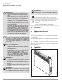
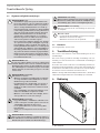
3. Appliance description
The appliance is a wall mounted electric direct heater.
The appliance is suitable for use as a standalone heating system,
or can be used in spring and autumn and as a booster heater in
smaller rooms.
The air inside the appliance is heated by a heating element and
expelled via natural convection through the air discharge at the
top. Cool indoor air is drawn in through the air intake on the
underside of the appliance.
When the set room temperature is reached, it is maintained by
periodic heating.
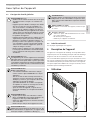
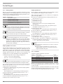
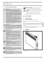
4. Operation
D0000068097
1
2
1 Programming unit
2 ON/OFF switch

OPERATION
Operation
ENGLISH
www.stiebel-eltron.com CWM P | CWM U | 5
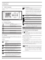
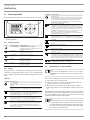
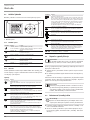
4.1 Programming unit
The programming unit is located at the top right of the appliance.
D0000068106
2
1
1 Display
2 User interface
4.1.1 User interface
Button Designation Description
"Standby" key
Switch on the programming unit;
Put programming unit and heating appliance
into standby mode
"OK" button
Selection;
Confirm settings
"Menu" key
Call up and exit menu
"+" key
Call up menu items;
Change settings
"–" key Call up menu items;
Change settings
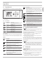
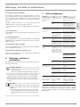
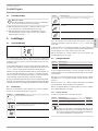
4.1.2 Display
If no user action occurs for 20seconds, the backlight switches
off. Press any button to switch the background lighting on again.
Symbols
Symbol Description
Time display:
Indication of the current time or a programmed start time
Timer mode:
The appliance heats in accordance with the enabled time pro-
gram.
Comfort mode:
The appliance maintains the set comfort temperature.
Standard setting: 21.0°C. Use this setting for comfortable room
temperatures when someone is present.
Setback mode:
The appliance maintains the set setback temperature.
Standard setting: 18.0°C. Use this setting e.g. at night or when
absent for several hours.
Frost protection:
The frost protection symbol is displayed if the set room tempera-
ture is set to 7.0°C.
Use this setting to protect an unused room from frost damage.
Adaptive start:
In timer mode, the heating appliance switching times are adjust-
ed to ensure that, at the programmed start time, the respective
set room temperature is already reached.
Conditions: The "adaptive start" function is enabled (see chapter
"Settings/ Standard menu").
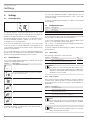
Symbol Description
Window open detection:
To avoid unnecessary energy consumption while venting, the
appliance automatically switches to frost protection mode for one
hour when a window is open. The "window open detection" sym-
bol flashes. After venting, frost protection mode can be terminat-
ed manually by pressing "+", "–" or "OK". The appliance then heats
to the set room temperature again.
Conditions: Window open detection is enabled (see chapter "Set-
tings/ Standard menu").
User interface lock:
To lock or unlock the user interface, press and hold "+" and "–"
simultaneously for 5seconds.
Heating enabled:
The appliance is heating to maintain the set room temperature.
Room temperature display
Editable parameter:
The parameter shown can be changed using "+" and "–".
External input (FP):
CWMU series appliances can be connected to an external control
unit. Depending on the control unit settings, the appliance heats
at specific times of the day in comfort, setback or frost protection
mode, or does not heat at all.
Days of the week:
1=Monday, 2=Tuesday … 7=Sunday
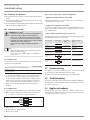
4.2 Switching the appliance on and off
Note
For a short time after initial start-up and after longer
breaks in use, a smell may develop.
The appliance is ready for operation as soon as it has been fixed
to the wall and plugged into the mains.
Switch the appliance on or off using the ON/OFF switch on
the right-hand side of the appliance.
Switch the appliance off when not in use for longer periods
(e.g. during the summer months).
All settings remain intact after switching off or after an interrup-
tion to the power supply. This appliance is equipped with a power
reserve that ensures the day of the week and the time are saved
for several hours.
Note
If the appliance was in timer mode before being switched
off for a longer period of time, you will be prompted to set
the day and time after switching it on. Until this setting
is made, the appliance will operate in comfort mode.
4.3 Standby mode
!
Material losses
In standby mode, the appliance will not switch on heating
under any circumstances. There will be no frost protec-
tion.
To switch on the programming unit, press "Standby". The
standard display appears.
To put the programming unit and the heating appliance into
standby mode, press "Standby". The display shows "- - - -".

OPERATION
Settings
6 | CWM P | CWM U www.stiebel-eltron.com
5. Settings
5.1 Standard display
D0000072134
The default display is continuously displayed. If no user action
is performed for longer than 20seconds while in the menu, the
appliance automatically switches to the default display.
The default display shows the current set room temperature as
well as the "Editable parameter" symbol. You can use "+" and "–"
to change the set room temperature.
If the set room temperature corresponds to one of the values
set for the comfort or setback temperature, the symbol for the
corresponding operating mode (comfort mode, setback mode)
appears in the menu bar.
The set room temperature can also be changed manually when
in timer mode. The changed set room temperature is maintained
until the next programmed switching point is reached.
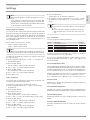
5.2 Standard menu
To access the standard menu, briefly press "Menu". You can now
call up the following menu items:
Display Description
Select day of the week and time
Select comfort temperature
The comfort temperature must be set at least 0.5°C higher
than the setback temperature.
Select setback temperature
Switch "Window open detection" function on and off
Select time program (Pro1, Pro2, Pro3, off) or external input
(FP)
Switch "Adaptive start" function on and off
To change the setting of a menu item, call it up by pressing "+"
and "–". Press the "OK" button.
As soon as the "Editable parameter" symbol appears, you can
change the setting of the menu item with "+" and "–". Press "OK"
to save the setting.
To exit the standard menu, briefly press "Menu". The standard
display appears.
5.3 Configuration menu
Display Description
I1-I2 Actual values
Pro1-Pro3 Time programs
P1-P5 Parameters
In the configuration menu, you can call up actual values, program
time programs for timer mode and set parameters.
To access the configuration menu, press and hold "Menu". After
approx.3seconds, actual valueI1 is displayed.
Use "+" and "–" to switch between the individual actual values,
time programs and parameters.
To exit the configuration menu, briefly press "Menu". The standard
display appears.
5.3.1 Actual values
The following actual values can be called up:
Display Description Unit
I1 Actual room temperature [°C] | [°F]
I2 Relative heating time
(The counter can be reset via parameter P5.)
[h]
Note
The counter for relative heating time(I2) counts in com-
plete hours how long the appliance heats for. When the
appliance is switched off, any heating phase of less than
60minutes is not recorded.
5.3.2 Time programs
There are three time programs available for using the appliance
in timer mode. Time programs Pro1 and Pro2 are factory-set.
Time program Pro3 can be set according to your individual re-
quirements.
Display Description
Pro1 Time program "Daily"
- Repeated: Monday to Sunday
Pro2 Time program "Weekdays"
- Repeated: Monday to Friday
Pro3 Time program "User defined"
- up to 14comfort phases, freely configurable
Note
To use timer mode, select the required time program
in the standard menu (see chapter "Settings/ Standard
menu").
Note
Ensure the day of the week and the time are set correctly
when setting the time programs.

OPERATION
Settings
ENGLISH
www.stiebel-eltron.com CWM P | CWM U | 7
Note
The following applies to all time programs (Pro1, Pro2,
Pro3):
If the end time is later than 23:59h, the end time will
automatically be moved to the next day of the week. The
comfort phase is maintained past midnight and will end
on the next day at the set end time.
Time programs Pro1 and Pro2
You can specify the comfort mode start and end times with time
programsPro1 and Pro2. During this time period, the appliance
heats to the set comfort temperature. Outside this specified time
period, the appliance operates in setback mode. This results in
a comfort and a setback phase that are repeated daily(Pro1) or
every weekday(Pro2).
Theses phases are factory-set as follows:
- 08:00 h - 22:00 h: Comfort mode
- 22:00 h - 08:00 h: Setback mode
Note
When time programPro2 is enabled, the appliance op-
erates exclusively in setback mode during the weekend.
To adapt time programsPro1 and Pro2 according to your needs,
proceed as follows:
In the configuration menu, use "+" and "–" to call up the re-
quired time program.
Press the "OK" button.
The start time for comfort mode is displayed.
Use "+" and "–" to set the required start time.
Press the "OK" button.
The end time for comfort mode is displayed.
Use "+" and "–" to set the required end time.
Press "OK" to save.
Time program Pro3
You can use time programPro3 to specify up to 14 separate com-
fort phases which are repeated weekly.
To configure a comfort phase in time programPro3:
In the configuration menu, use "+" and "–" to call up time
programPro3.
Press the "OK" button.
The display shows "3---".
Press the "OK" button.
A day of the week or a group of days is displayed.
Use "+" and "–" to select the required day or group of days.
Press the "OK" button.
The start time for comfort mode is displayed.
Use "+" and "–" to set the required start time.
Press the "OK" button.
The end time for comfort mode is displayed.
Use "+" and "–" to set the required end time.
Press the "OK" button.
Comfort phase "3-01" has been configured.
To configure a further comfort phase, use "+" and "–" in time
programPro3 to select display"3---". Proceed as describe
above.
Note
To reset the selected comfort phases, activate parame-
terP4.
Please note that activating parameterP4 resets all
time programs (Pro1, Pro2, Pro3) to the factory set-
ting.
5.3.3 Parameters
You can call up the following parameters:
Display Description Options
P1 Room temperature offset ±3°C | ±5°F
P2 Time format 12h | 24h
P3 Temperature display units °C | °F
P4 Reset time programs (timer mode). on | off
P5 Reset relative heating time on | off
To change the value of a parameter, use "+" and "–" to call up the
relevant parameter. Press the "OK" button.
As soon as the "Editable parameter" symbol appears, you can
change the parameter value with "+" and "–". Press "OK" to save
the selected value.
P1: Room temperature offset
Uneven temperature distribution in the room can result in a differ-
ence between displayed actual temperatureI1 and the room tem-
perature you measure yourself. To compensate for this difference,
a room temperature offset of ±3°C can be set via parameterP1.
Example: The appliance indicates I1=21.0°C. You have measured
a room temperature of 20.0°C. There is a difference of 1.0°C.
To compensate for the difference, select an offset of P1=-1.0.
P2: Time format
ParameterP2 is used to specify whether to display the time in 12
hour or 24 hour format.
P3: Temperature display units
ParameterP3 is used to specify whether the room temperature is
displayed in degrees Centigrade [°C] or in degrees Fahrenheit [°F].
P4: Reset time programs
Activating parameterP4 resets all time programs to the factory
setting.
P5: Reset relative heating time
Activating parameterP5 resets the counter for relative heating
time (I2).

8 | CWM P | CWM U www.stiebel-eltron.com
OPERATION | INSTALLATION
Cleaning, care and maintenance
6. Cleaning, care and maintenance
The appliance contains no user serviceable parts.
Material losses
- Never spray cleaning spray into the air slot.
- Ensure that no moisture can enter the appliance.
- If a pale brownish discolouration appears on the appliance
casing, wipe it off with a damp cloth.
- Clean the appliance when cold with ordinary cleaning prod-
ucts. Avoid abrasive or corrosive cleaning products.
Note
We recommend having the control components checked
as part of regular maintenance.
Have a qualified contractor check the safety and
control components no more than 10years after
commissioning.
7. Troubleshooting
Problem Cause Remedy
Room does not get
warm enough. Ap-
pliance does not get
hot.
Temperature set too low
on the appliance.
Check the selected room
temperature. Adjust if nec-
essary.
No power supply.
Check position of the ON/OFF
switch, RCD and fuse/MCB in
your fuse box.
Room does not get
warm enough al-
though the appliance
is hot.
Overheating. High limit
safety cut-out limits
heating output.
Eliminate the cause (dirt or
obstructions at the air inlet
or outlet). Observe minimum
clearances.
The heat demand of the
room is higher than ap-
pliance output.
Remove heat losses (Close
windows and doors. Avoid
constant venting.)
Room gets too hot.
Temperature set too high
on the appliance.
Check the selected room
temperature. Adjust if nec-
essary.
Detected room tempera-
ture does not match actu-
al room temperature.
Avoid obstructions to air
change between appliance
and indoor air.
Window open de-
tection does not
respond.
Appliance does not detect
a pronounced tempera-
ture drop due to venting.
(Window open detection
requires previously sta-
ble room temperature.)
Wait a while after making
settings on the appliance,
until the room temperature
has fully stabilised.
Avoid obstructions to air
change between appliance
and indoor air.
Manually switch the appli-
ance into standby mode for
the duration of venting.
Window open detection
is not enabled.
Switch on window open
detection in the standard
menu.
"Adaptive start" func-
tion does not work as
required.
This function is only ef-
fective in timer mode.
Use the timer mode for opti-
mised heating convenience.
Severely fluctuating room
temperature or the appli-
ance learning procedure
has not been completed.
Wait a few days for behav-
iour to stabilise.
“Adaptive start” function
is not enabled.
Switch on the "Adaptive
start" function in the stand-
ard menu.
Problem Cause Remedy
Appliance is in "FP"
program but does not
respond to external
input.
When the appliance does
not detect a signal at the
external input, it heats in
comfort mode.
Check external control unit
and its settings. Wiring must
be installed correctly and
with correct polarity.
"Err" or "E..." is dis-
played.
Internal fault detected. Notify the qualified con-
tractor.
If you cannot remedy the fault, contact your qualified contractor.
To facilitate and speed up your request, provide the number from
the type plate (000000-0000-000000).
INSTALLATION
8. Safety
Only a qualified contractor should carry out installation, commis-
sioning, maintenance and repair of the appliance.
8.1 General safety instructions
We guarantee trouble-free function and operational reliability only
if original accessories and spare parts intended for the appliance
are used.
CAUTION Burns
- Only mount the appliance on a vertical wall that is
temperature-resistant to at least 85°C.
- Maintain the minimum clearances to adjacent ob-
jects.
!
Material losses
- Never install the appliance directly below a wall
socket.
- Ensure that the power cable is not in contact with
any appliance components.
8.2 Instructions, standards and regulations
Note
Observe all applicable national and regional regulations
and instructions.
9. Appliance description
9.1 Standard delivery
The following are delivered with the appliance:
- Wall mounting bracket (hooked into the appliance)

INSTALLATION
Installation
ENGLISH
www.stiebel-eltron.com CWM P | CWM U | 9
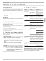
10. Installation
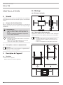
10.1 Minimum clearances
≥150≥100
≥100 ≥100 ≥500
≥20
D0000068096
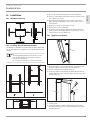
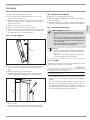
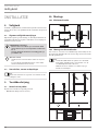
10.2 Installing the wall mounting bracket
The appliance is intended for wall mounting using the wall mount-
ing bracket supplied. The appliance may only be installed hori-
zontally.
Note
- The wall mounting bracket can be used as a tem-
plate for wall mounting. This ensures sufficient
clearance from the floor.
- Use a spirit level if the floor is uneven or sloping.
aaa
D0000072159
1
3
2
4
≥224 ≥224
D0000072312
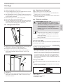
Unhook the wall mounting bracket from the appliance.
Place the centred wall mounting bracket horizontally on the
floor. Mark holes1 and 2.
Lift up the wall mounting bracket so that its lower holes
match up with the markings you have just made on the in-
stallation wall.
Mark holes3 and 4 on the installation wall.
Drill the holes at the 4markings.
Secure the wall mounting bracket with suitable fixing ma-
terials (screws, rawl plugs). With the vertical slots, you can
compensate for an offset fixing hole.
10.3 Appliance installation
D0000072157
1
1 Wall mounting bracket
Hook the appliance onto the bottom tabs of the wall mount-
ing bracket by the slots in the back of the appliance.
Place the appliance in an upright position.
Secure the appliance by pushing it towards the wall until it
audibly snaps into place in the two upper springs on the wall
mounting bracket.
D0000072158
1
2
1 Appliance
2 Locking screw
Secure the appliance against unintentional release using
the supplied locking screw on the left-hand side of the wall
mounting bracket.

INSTALLATION
Commissioning
10 | CWM P | CWM U www.stiebel-eltron.com
10.4 Removing the appliance
Undo and remove the locking screw from the wall mounting
bracket.
To release the appliance, push down the springs at the top of
the wall mounting bracket.
Tilt the appliance away from the wall and lift it off the bottom
tabs on the wall mounting bracket.
10.5 Electrical connection
WARNING Electrocution
- Carry out all electrical connection and installation
work in accordance with relevant regulations.
- In the case of a permanent connection, the appli-
ance must be able to be separated from the power
supply by an isolator that disconnects all poles with
at least 3mm contact separation.
- Do not install the appliance with a fixed power
cable.
Note
- Observe the type plate. The specified voltage must
match the mains voltage.
- Ensure the on-site supply cable has an adequate
cross-section.
10.5.1 CWM P series
The appliance is delivered fully wired. The following electrical
connections are permissible:
CWM 500-3000 P
Connection to a freely accessible standard socket
with matching plug
X
Permanent connection to an appliance junction box
with earth conductor
X
- If connecting the appliance via a socket, ensure that this is
easily accessible once the appliance has been installed.
- If connecting the appliance permanently, trim the power
cable so that it leads directly to the appliance connection
socket. Ensure that, after trimming the power cable, the
appliance can still be removed from the wall without a
problem.
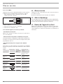
10.5.2 CWM U series
The appliance is delivered with a power cable without a plug.
When wiring the appliance in permanently, connect the
4-core cable to a connection socket as illustrated:
1
2
3
4
1
2
3
4
D0000068123
1 Neutral conductor = blue
2 Live = brown
3 Earth conductor = green/yellow
4 Control cable = black
There are 3 possible ways to connect the appliance:
- Appliance connection without control cable
Unregulated appliance. The control cable is not connected. In this
case, insulate the control cable.
- Temperature setback via control cable
To reduce the temperature to the set setback temperature, the
black control cable is activated via an external electronic contact
(e.g. a time switch).
- Control cable connected to external control unit
The appliance can be connected to any control unit that issues the
following waveforms as control signals.
Instruction Oscilloscope Operating
mode
Heating temper-
ature
No electrical
power
Comfort mode Subject to set comfort
temperature
Complete oscil-
lation 230 V
Setback mode Subject to set setback
temperature
Semi-oscillation
negative -115V
Frost protection Frost protection tem-
perature
Semi-oscillation
positive +115V
Stop None
Full oscillation
230V for 3sec-
onds
Comfort mode
-1°C
1°C less than the set
comfort temperature
Full oscillation
230V for 7sec-
onds
Comfort mode
-2°C
2°C less than the set
comfort temperature
11. Commissioning
The appliance is ready for operation as soon as it has been fixed
to the installation wall and plugged into the mains.
Remove the protective film from the programming unit.
12. Troubleshooting
The power cable must only be replaced (for example if damaged)
by a qualified contractor authorised by the manufacturer, using
an original spare part.
13. Appliance handover
Explain the functions of the appliance to the user. Draw special
attention to the safety instructions. Hand over the operating and
installation instructions to the user.

INSTALLATION
ENGLISH
www.stiebel-eltron.com CWM P | CWM U | 11
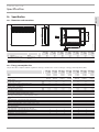
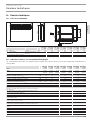
14. Specification
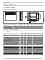
14.1 Dimensions and connections
b01
a20
450
100
256
i13
D0000068095
CWM 500
P/U
CWM 750
P/U
CWM 1000
P/U
CWM 1500
P/U
CWM 2000
P/U
CWM 2500
P/U
CWM 3000
P/U
a20 Appliance Width mm 348 426 426 582 738 894 1050
i13 Wall mounting bracket Horizontal hole
spacing
mm 101 179 179 335 491 647 803
b01 Entry electrical cables
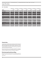
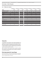
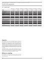
14.2 Energy consumption data
The product data complies with EU regulations relating to the Directive on the ecodesign of energy related products (ErP).
CWM 500
P/U
CWM 750
P/U
CWM 1000
P/U
CWM 1500
P/U
CWM 2000
P/U
CWM 2500
P/U
CWM 3000
P/U
CWM P
CWM U
200254
200261
200255
200262
200256
200263
200257
200264
200258
200265
200259
200266
200260
200267
Manufacturer STIEBEL
ELTRON
STIEBEL
ELTRON
STIEBEL
ELTRON
STIEBEL
ELTRON
STIEBEL
ELTRON
STIEBEL
ELTRON
STIEBEL
ELTRON
Heating output
Rated heating output P
nom
kW 0,5 0,8 1,0 1,5 2,0 2,5 3,0
Minimum heating output (standard value) P
min
kW 0,0 0,0 0,0 0,0 0,0 0,0 0,0
Maximum continuous heating output P
max,c
kW 0,5 0,8 1,0 1,5 2,0 2,5 3,0
Auxiliary power consumption
At rated heating output el
max
kW 0.000 0.000 0.000 0.000 0.000 0.000 0.000
At minimum heating output el
min
kW 0.000 0.000 0.000 0.000 0.000 0.000 0.000
In standby el
SB
kW 0.000 0.000 0.000 0.000 0.000 0.000 0.000
Type of heating output/room temperature control
Single stage heating output, no room temperature control - - - - - - -
Two or more manually selectable stages, no room temperature
control
- - - - - - -
Room temperature control with mechanical thermostat - - - - - - -
With electronic room temperature control - - - - - - -
Electronic room temperature control and time of day control - - - - - - -
Electronic room temperature control and day of week control x x x x x x x
Other control options
Room temperature control with presence detection - - - - - - -
Room temperature control with window open detection x x x x x x x
With remote control option - - - - - - -
With adaptive control of heating start x x x x x x x
With operating time limitation - - - - - - -
With black bulb sensor - - - - - - -

12 | CWM P | CWM U www.stiebel-eltron.com
INSTALLATION | GUARANTEE | ENVIRONMENT AND RECYCLING
Guarantee
The guarantee conditions of our German companies do not
apply to appliances acquired outside of Germany. In countries
where our subsidiaries sell our products a guarantee can only
be issued by those subsidiaries. Such guarantee is only grant-
ed if the subsidiary has issued its own terms of guarantee. No
other guarantee will be granted.
We shall not provide any guarantee for appliances acquired in
countries where we have no subsidiary to sell our products.
This will not aect warranties issued by any importers.
Environment and recycling
We would ask you to help protect the environment. After use,
dispose of the various materials in accordance with national
regulations.
GUARANTEE
ENVIRONMENT AND RECYCLING
14.3 Data table
CWM 500 P/U CWM 750 P/U CWM 1000 P/U CWM 1500 P/U CWM 2000 P/U CWM 2500 P/U CWM 3000 P/U
CWM P
CWM U
200254
200261
200255
200262
200256
200263
200257
200264
200258
200265
200259
200266
200260
200267
Electrical data
Connected load W 500 750 1000 1500 2000 2500 3000
Power supply 1/N/PE ~ 230 V 1/N/PE ~ 230 V 1/N/PE ~ 230 V 1/N/PE ~ 230 V 1/N/PE ~ 230 V 1/N/PE ~ 230 V 1/N/PE ~ 230 V
Rated current A 2.2 3.3 4.3 6.5 8.7 10.9 13.0
Frequency Hz 50/- 50/- 50/- 50/- 50/- 50/- 50/-
Dimensions
Height mm 450 450 450 450 450 450 450
Width mm 348 426 426 582 738 894 1050
Depth mm 100 100 100 100 100 100 100
Weights
Weight kg 4.0 4.6 4.6 6.0 7.7 9.2 10.9
Versions
Frost protection setting °C 7 7 7 7 7 7 7
Version
Wall mounted
appliance
Wall mounted
appliance
Wall mounted
appliance
Wall mounted
appliance
Wall mounted
appliance
Wall mounted
appliance
Wall mounted
appliance
IP rating IP24 IP24 IP24 IP24 IP24 IP24 IP24
Protection class I I I I I I I
Colour Alpine white Alpine white Alpine white Alpine white Alpine white Alpine white Alpine white
Values
Setting range °C 5-30 5-30 5-30 5-30 5-30 5-30 5-30

www.stiebel-eltron.com CWM P | CWM U | 13
FRANÇAIS
TABLE DES MATIÈRES | REMARQUES PARTICULIÈRES
REMARQUES
PARTICULIÈRES
- Veuillez tenir les enfants de moins de 3ans
éloignés de l’appareil s’ils ne sont pas sous
constante surveillance.
- L’appareil peut être allumé et éteint par des
enfants âgés de 3 à 7 ans s’ils sont sous sur-
veillance ou s’ils ont été formés à son utilisa-
tion en toute sécurité et qu’ils ont compris les
dangers encourus. La condition préalable est
que l’appareil ait été monté comme décrit. Il
est interdit aux enfants de 3 à 7 ans de bran-
cher la prise électrique ou d’intervenir sur la
régulation de l’appareil.
- L’appareil peut être utilisé par des enfants de
8ans et plus ainsi que par des personnes aux
facultés physiques, sensorielles ou mentales
réduites, ou par des personnes sans expé-
rience, lorsqu’ils sont sous surveillance ou
qu’ils ont été formés à l’utilisation en toute
sécurité de l’appareil et qu’ils ont compris les
dangers encourus.
- Ne laissez pas les enfants jouer avec l’appa-
reil. Ni le nettoyage ni la maintenance rele-
vant de l’utilisateur ne doivent être effectués
par des enfants sans surveillance.
- Certaines parties de l’appareil peuvent être
à très haute température et causer des
brûlures. La présence d’enfants ou de per-
sonnes vulnérables requiert une attention
particulière.
- Afin d’éviter la surchauffe de l’appareil, veuil-
lez ne pas le couvrir.
- N’installez pas l’appareil directement sous
une prise électrique murale.
- En cas de raccordement fixe, l’appareil doit
pouvoir être séparé du raccordement secteur
par un dispositif de coupure omnipolaire
ayant une ouverture minimale des contacts de
3mm.
REMARQUES PARTICULIÈRES
UTILISATION
1. Remarques générales ������������������������������������� 14
1.1 Consignes de sécurité ������������������������������������������ 14
1.2 Autres symboles utilisés dans cette documentation ����� 14
1.3 Remarques apposées sur l’appareil ������������������������ 14
1.4 Unités de mesure ����������������������������������������������� 14
2. Sécurité ����������������������������������������������������� 14
2.1 Utilisation conforme ������������������������������������������� 14
2.2 Consignes de sécurité générales ���������������������������� 15
2.3 Label de conformité �������������������������������������������� 15
3. Description de l’appareil ���������������������������������� 15
4. Utilisation ��������������������������������������������������� 15
4.1 Unité de commande �������������������������������������������� 16
4.2 Mise en marche et arrêt de l’appareil ���������������������� 16
4.3 Mode veille ������������������������������������������������������� 17
5. Réglages ���������������������������������������������������� 17
5.1 Affichage standard ��������������������������������������������� 17
5.2 Menu principal �������������������������������������������������� 17
5.3 Menu de paramétrage ����������������������������������������� 17
6. Nettoyage, entretien et maintenance �������������������� 19
7. Aide au dépannage ���������������������������������������� 19
INSTALLATION
8. Sécurité ����������������������������������������������������� 20
8.1 Consignes de sécurité générales ����������������������������20
8.2 Prescriptions, normes et réglementations����������������� 20
9. Description de l’appareil ���������������������������������� 20
9.1 Fourniture �������������������������������������������������������� 20
10. Montage ����������������������������������������������������� 20
10.1 Distances minimales �������������������������������������������20
10.2 Montage de la fixation murale �������������������������������20
10.3 Pose de l’appareil ����������������������������������������������� 21
10.4 Démontage de l’appareil �������������������������������������� 21
10.5 Raccordement électrique ������������������������������������� 21
11. Mise en service ��������������������������������������������� 22
12. Aide au dépannage ���������������������������������������� 22
13. Remise de l’appareil au client ���������������������������� 22
14. Données techniques ��������������������������������������� 23
14.1 Cotes et raccordements ���������������������������������������� 23
14.2 Indications relatives à la consommation énergétique ��� 23
14.3 Tableau des données ������������������������������������������� 24
GARANTIE
ENVIRONNEMENT ET RECYCLAGE

UTILISATION
Remarques générales
14 | CWM P | CWM U www.stiebel-eltron.com
- En cas de détérioration ou de changement du
câble d’alimentation, celui-ci doit uniquement
être remplacé par une pièce de rechange
d’origine, par un installateur agréé par le
fabricant.
- Fixez l’appareil comme indiqué dans le cha-
pitre «Installation/ Montage».
UTILISATION
1. Remarques générales
Les chapitres «Remarques particulières» et «Utilisation»
s’adressent à l’utilisateur de l’appareil et à l’installateur.
Le chapitre «Installation» s’adresse à l’installateur.
Remarque
Lisez attentivement cette notice avant utilisation et
conservez-la.
Remettez cette notice à tout nouvel utilisateur le cas
échéant.
1.1 Consignes de sécurité
1.1.1 Structure des consignes de sécurité
MENTION D’AVERTISSEMENT Nature du danger
Sont indiqués ici les risques éventuellement encourus en
cas de non-respect de la consigne de sécurité.
Indique les mesures permettant d’éviter le danger.
1.1.2 Symboles, nature du danger
Symbole Nature du danger
Blessure
Électrocution
Brûlure
(brûlure, ébouillantement)
1.1.3 Mentions d’avertissement
MENTION
D’AVERTISSE-
MENT
Signification
DANGER Les consignes de sécurité dont le non-respect entraîne de
graves lésions, voire la mort.
AVERTISSEMENT Les consignes de sécurité dont le non-respect peut entraî-
ner de graves lésions, voire la mort.
ATTENTION Les consignes de sécurité dont le non-respect peut entraî-
ner des lésions légères ou moyennement graves.
1.2 Autres symboles utilisés dans cette
documentation
Remarque
Le symbole ci-contre caractérise des remarques géné-
rales.
Lisez attentivement les remarques.
Symbole Signification
Dommages matériels
(Dégats induits, dommages causés à l’appareil, à l’envi-
ronnement)
Recyclage de l’appareil
Ce symbole indique que vous devez intervenir. Les actions
nécessaires sont décrites étape par étape.
1.3 Remarques apposées sur l’appareil
Symbole Signification
Ne pas couvrir l’appareil
1.4 Unités de mesure
Remarque
Sauf indication contraire, toutes les cotes sont indiquées
en millimètres.
2. Sécurité
2.1 Utilisation conforme
Cet appareil est conçu pour le chauffage de locaux d’habitation.
L’appareil est destiné à une utilisation domestique. Il peut être
utilisé sans risque par des personnes qui ne disposent pas de
connaissances techniques particulières. L’appareil peut également
être utilisé dans un environnement non domestique, par exemple
dans de petites entreprises, à condition que son utilisation soit
du même ordre.
Tout autre emploi est considéré comme non conforme. Une uti-
lisation conforme de l’appareil implique également le respect de
cette notice et de celles des accessoires utilisés.

UTILISATION
Description de l’appareil
www.stiebel-eltron.com CWM P | CWM U | 15
FRANÇAIS
2.2 Consignes de sécurité générales
!
AVERTISSEMENT Blessure
- Veuillez tenir les enfants de moins de 3ans éloignés
de l’appareil s’ils ne sont pas sous constante sur-
veillance.
- L’appareil peut être allumé et éteint par des enfants
âgés de 3 à 7 ans s’ils sont sous surveillance ou
s’ils ont été formés à son utilisation en toute sécu-
rité et qu’ils ont compris les dangers encourus. La
condition préalable est que l’appareil ait été monté
comme décrit. Il est interdit aux enfants de 3 à 7 ans
de brancher la prise électrique ou d’intervenir sur
la régulation de l’appareil.
- L’appareil peut être utilisé par des enfants de 8ans
et plus ainsi que par des personnes aux facultés
physiques, sensorielles ou mentales réduites, ou
par des personnes sans expérience, lorsqu’ils sont
sous surveillance ou qu’ils ont été formés à l’utili-
sation en toute sécurité de l’appareil et qu’ils ont
compris les dangers encourus.
- Ne laissez pas les enfants jouer avec l’appareil. Ni
le nettoyage ni la maintenance relevant de l’utilisa-
teur ne doivent être effectués par des enfants sans
surveillance.
!
AVERTISSEMENT Blessure
La température peut s’élever rapidement et de manière
importante dans les locaux fermés. Si l’appareil est uti-
lisé dans un local de petite taille et que les personnes
s’y trouvant ne peuvent pas procéder à la régulation par
elles-mêmes ou quitter le local, il convient d’assurer une
surveillance permanente.
AVERTISSEMENT Brûlure
N’utilisez pas l’appareil...
- si les distances minimales aux surfaces d’objets
voisins ou autres objets inflammables ne sont pas
suffisantes.
- dans les locaux où existe un risque d’incendie ou
d’explosion en raison de la présence de produits
chimiques, poussières, gaz ou vapeurs. Aérez suffi-
samment le local avant de chauffer.
- à proximité immédiate de conduites ou récipients
susceptibles de contenir ou de transporter des ma-
tériaux inflammables ou explosibles.
- après une chute de l’appareil, ou après un fonc-
tionnement défaillant, ou si un dysfonctionnement
survient.
AVERTISSEMENT Brûlure
- Ne placez pas d’objets ou de substances combus-
tibles ou inflammables ni d’isolants thermiques sur
l’appareil ou dans sa proximité immédiate.
- Veillez à ne jamais bloquer les ouvertures d’arrivée
et de sortie d’air.
- N’intercalez pas d’objet entre l’appareil et le mur.
AVERTISSEMENT Brûlure
L’appareil n’est pas prévu pour être utilisé sur socle. Uti-
lisez exclusivement cet appareil avec le support mural
fourni (voir chapitre «Installation/ Montage»).
ATTENTION Brûlure
Certaines parties de l’appareil peuvent être à très haute
température et causer des brûlures. La présence d’en-
fants ou de personnes vulnérables requiert une attention
particulière.
AVERTISSEMENT Surchauffe
Afin d’éviter la surchauffe de l’appareil, veuillez ne pas
le couvrir.
!
Dommages matériels
- Veillez à ce que le câble d’alimentation ne se trouve
pas contre l’appareil.
- Ne montez pas sur l’appareil.
- N’utilisez pas l’appareil à l’extérieur.
2.3 Label de conformité
Voir la plaque signalétique sur l’appareil.
3. Description de l’appareil
Cet appareil est un appareil de chauffage électrique mural direct.
L’appareil peut servir de chauffage principal ou bien de chauffage
d’appoint ou de mi-saison dans les locaux de taille réduite.
L’air est chauffé dans l’appareil par un corps de chauffe et ressort
par convection naturelle par la grille supérieure. Parallèlement, de
l’air ambiant frais pénètre par l’entrée d’air située sous l’appareil.
Lorsque la température ambiante de consigne est atteinte, elle est
maintenue par un chauffage intermittent.
4. Utilisation
D0000068097
1
2
1 Unité de commande
2 Interrupteur principal

UTILISATION
Utilisation
16 | CWM P | CWM U www.stiebel-eltron.com
4.1 Unité de commande
L’unité de commande se situe dans la partie supérieure droite de
l’appareil.
D0000068106
2
1
1 Affichage
2 Module de commande
4.1.1 Module de commande
Touche Dénomination Description
Touche «veille»
Allumer l’unité de commande;
Mise en position veille de l’unité de com-
mande et du convecteur
Touche «OK»
Sélection;
Confirmation des réglages
Touche «Menu»
Appeler et quitter les menus
Touche «+»
Accès aux rubriques des menus;
Modification des réglages
Touche «–» Accès aux rubriques des menus;
Modification des réglages
4.1.2 Affichage
En l’absence d’action de l’utilisateur pendant 20 secondes, le ré-
tro-éclairage s’éteint. Appuyez sur une touche quelconque pour
réactiver le rétro éclairage.
Symboles
Symbole Description
Horloge:
affichage de l’heure courante ou d’une heure de démarrage pro-
grammée
Mode programmateur:
L’appareil chauffe en fonction du programme en cours.
Mode confort:
L’appareil régule à la température de confort préréglée.
Par défaut: 21°C. Conserver ce réglage pour une température
ambiante de confort en présence des occupants.
Mode réduit:
l’appareil régule à la température réduite préréglée.
Par défaut: 18°C. Utilisez ce réglage la nuit ou en cas d’absence
des occupants pendant quelques heures.
Protection hors gel:
Lorsque la température ambiante de consigne est réglée sur
7,0°C, le symbole de protection hors gel est affiché.
Utilisez ce réglage pour la protection hors gel d’un local inutilisé.
Démarrage adapté:
En mode programmateur, l’heure de démarrage du convecteur
est adaptée en fonction de la durée nécessaire pour atteindre la
température ambiante de consigne à l’heure programmée.
Condition requise: la fonction «démarrage adapté» est activée
(voir chapitre «Réglages/ Menu principal»).
Symbole Description
Détection de fenêtre ouverte:
Pour éviter les consommations inutiles d’énergie lors de l’aé-
ration des locaux, l’appareil passe automatiquement en mode
protection hors gel pendant une heure lorsqu’une fenêtre est
ouverte. L’icône «Fenêtre ouverte» clignote. Vous pouvez quitter
le mode protection hors gel après l’aération en activant manuel-
lement une des touches «+», «–» ou «OK». L’appareil chauffe
de nouveau le local à la température ambiante de consigne pré-
réglée.
Condition requise: La détection de fenêtre ouverte est activée
(voir chapitre «Réglages/ Menu principal»).
Verrouillage des commandes:
pour verrouiller ou déverrouiller l’unité de commande, mainte-
nez les touches «+» et «–» appuyées simultanément pendant
5secondes.
Chauffage actif:
l’appareil chauffe pour maintenir la température ambiante de
consigne préréglée.
Affichage de la température ambiante
Paramètre modifiable:
le paramètre affiché peut être modifié à l’aide des touches «+»
ou «–».
Entrée externe (FP):
Les appareils de type CWMU peuvent être raccordés à une unité
de commande externe. L’appareil chauffe en mode confort, réduit
ou protection hors gel selon les horaires paramétrés sur l’appa-
reil de commande, ou il ne chauffe pas du tout.
Jours de la semaine:
1=lundi, 2=mardi… 7=dimanche
4.2 Mise en marche et arrêt de l’appareil
Remarque
Lors de la première mise en service ou suite à un arrêt de
fonctionnement prolongé, des odeurs peuvent se dégager
temporairement.
L’appareil est prêt à fonctionner dès qu’il a été fixé au mur et
branché sur une prise secteur.
Allumez ou éteignez l’appareil en actionnant l’interrupteur
situé sur le côté droit.
En cas d’inutilisation prolongée, (pendant l’été par exemple),
éteignez l’appareil.
Les paramétrages restent conservés lorsque l’appareil est éteint
ou lors d’une coupure de courant. Cet appareil possède une cer-
taine autonomie permettant de conserver le jour de la semaine
et l’heure courants pendant plusieurs heures.
Remarque
Lors d’une remise en marche après un arrêt prolongé
alors que l’appareil était en mode programmateur, il
vous sera demandé de procéder à un nouveau réglage
de l’heure et du jour de la semaine courants. L’appareil
fonctionnera en mode confort jusqu’à ce que ce réglage
soit effectué.

UTILISATION
Réglages
www.stiebel-eltron.com CWM P | CWM U | 17
FRANÇAIS
4.3 Mode veille
!
Dommages matériels
En mode veille le chauffage n’est jamais mis en marche.
La protection hors gel n’est pas assurée.
Pour allumer l’unité de commande, appuyez sur la touche
«Veille». L’affichage standard apparaît.
Pour que l’unité de commande et le convecteur passent en
mode veille, appuyez sur la touche «Veille». L’écran affiche
«- - - -».
5. Réglages
5.1 Affichage standard
D0000072134
L’écran par défaut reste affiché en permanence. Si vous vous
trouvez dans le menu et n’effectuez aucune commande pendant
20secondes, l’appareil repasse automatiquement à l’affichage
par défaut.
Celui-ci indique la température ambiante de consigne en cours
ainsi que l’icône «Paramètre modifiable». Vous pouvez modifier
cette température de consigne à l’aide des touches «+» et «–».
Lorsque la température ambiante de consigne correspond à la
valeur préréglée pour la température de confort ou réduite, l’icône
correspondant au mode de fonctionnement s’affiche dans la barre
de menu (confort ou réduit).
La température ambiante de consigne peut également être mo-
difiée en mode programmateur. La température ambiante de
consigne reste maintenue jusqu’à la fin de la plage horaire pro-
grammée.
5.2 Menu principal
Pour accéder au menu principal, appuyez brièvement sur la touche
«Menu». Vous pouvez alors accéder aux rubriques suivantes:
Affichage Description
Réglage du jour de la semaine et de l’heure
Réglage de la température de confort
La température de confort doit être supérieure d’au moins
0,5°C à la température réduite.
Réglage de la température réduite
Affichage Description
Activation/désactivation de la fonction «Détection de fenêtre
ouverte»
Sélection du programme de temporisation (Pro1, Pro2, Pro3,
off) ou de l’entrée externe (FP)
Activation/ désactivation de la fonction «Démarrage adapté»
Si vous souhaitez modifier les valeurs d’une rubrique de menu,
appelez celle-ci à l’aide des touches «+» et «–». Appuyez sur
la touche «OK».
La modification par les touches «+» et «–» est possible si l’icône
«Paramètre modifiable» est affichée. Appuyez sur la touche
«OK» pour enregistrer le réglage.
Pour quitter le menu principal, appuyez sur la touche «Menu».
L’affichage standard apparaît.
5.3 Menu de paramétrage
Affi-
chage
Description
I1-I2 Valeurs réelles
Pro1-Pro3 Programmes de temporisation
P1-P5 Paramètre
Dans le menu de paramétrage, vous pouvez accéder aux valeurs
réelles régissant la programmation et définir divers paramètres.
Pour accéder au menu de paramétrage, maintenez la touche
«Menu» appuyée. La valeur réelleI1 s’affiche après 3secondes
env.
Vous pouvez naviguer entre les différentes valeurs réelles et entre
les différents programmes et paramètres à l’aide des touches
«+» et «–».
Pour quitter le menu de paramétrage, appuyez sur la touche
«Menu». L’affichage standard apparaît.
5.3.1 Valeurs réelles
Vous pouvez accéder aux valeurs réelles suivantes:
Affi-
chage
Description Unité
I1 Valeur réelle de la température ambiante [°C] | [°F]
I2
Temps de chauffe relatif
(le paramètre P5 permet de réinitialiser ce comp-
teur)
[h]
Remarque
Le compteur du temps de chauffe relatif(l2) additionne
le temps pendant lequel le convecteur a effectivement
chauffé, en heures pleines. Lorsque l’appareil est éteint,
les phases de chauffe inférieures à 60minutes ne sont
pas comptées.

UTILISATION
Réglages
18 | CWM P | CWM U www.stiebel-eltron.com
5.3.2 Programmes de temporisation
Vous disposez de 3 programmes pour le fonctionnement en mode
programmateur. Les programmes Pro1 et Pro2 sont préconfigu-
rés en usine. Vous pouvez définir le programme Pro3 selon vos
besoins personnels.
Affi-
chage
Description
Pro1 Programme «tous les jours»
- répétition: du lundi au dimanche
Pro2 Programme «jours ouvrables»
- répétition: du lundi au vendredi
Pro3 Programme «personnalisé»
- jusqu’à 14 phases de confort en configuration libre
Remarque
Si vous désirez utiliser le programmateur, vous devez
choisir le programme qui vous convient dans le menu
principal (voir chapitre «Réglages/ Menu principal»).
Remarque
Lors de la programmation, assurez-vous que l’heure et
le jour de la semaine courants sont corrects.
Remarque
La remarque suivante est valable pour chacun des pro-
grammes (Pro1, Pro2, Pro3):
si la plage programmée se termine après 23 h 59, l’ho-
raire de fin sera automatiquement reporté sur le jour
suivant. La plage de confort sera maintenue après minuit
et se terminera le lendemain à l’heure programmée.
Programmes Pro1 et Pro2
Les programmes Pro1 et Pro2 permettent de définir les horaires
de démarrage et de fin du fonctionnement en mode confort. Du-
rant cette période, l’appareil chauffe à la température de confort
préréglée. En dehors de cette plage, il fonctionne en mode réduit.
Vous pouvez ainsi programmer une phase confort et une phase
de fonctionnement à température réduite pour tous les jours de
la semaine (Pro1) ou différente pour chaque jour (Pro2).
La configuration usine est la suivante:
- de 08 h 00 à 22 h 00: Mode CONFORT
- de 22 h 00 à 08 h 00: Mode réduit
Remarque
Si le programme Pro2 est activé, l’appareil fonctionne
exclusivement en mode réduit pendant le weekend.
Procédez comme suit pour adapter les programmesPro1 et Pro2
à vos besoins:
dans le menu de paramétrage, appelez le programme sou-
haité à l’aide des touches «+» et «–».
Appuyez sur la touche «OK».
L’heure de départ du mode confort s’affiche.
Programmez l’heure de départ souhaitée à l’aide des touches
«+» et «–».
Appuyez sur la touche «OK».
L’heure de fin du mode confort s’affiche.
Programmez l’heure de fin souhaitée à l’aide des touches
«+» et «–».
Appuyez sur la touche «OK» pour enregistrer ces horaires.
Programme Pro3
Avec le programme Pro3, vous pouvez définir jusqu’à 14 plages
horaires de mode confort séparées, celles-ci se répétant à l’iden-
tique d’une semaine sur l’autre.
Procédez comme suit pour paramétrer une plage horaire du pro-
gramme Pro3:
dans le menu de paramétrage, appelez le programme Pro3 à
l’aide des touches «+» et «–».
Appuyez sur la touche «OK».
L’écran affiche «3---».
Appuyez sur la touche «OK».
L’écran affiche un jour / un groupe de jours de la semaine.
Définissez le jour / le groupe de jours de la semaine souhaité
à l’aide des touches «+» et «–».
Appuyez sur la touche «OK».
L’heure de départ du mode confort s’affiche.
Programmez l’heure de départ souhaitée à l’aide des touches
«+» et «–».
Appuyez sur la touche «OK».
L’heure de fin du mode confort s’affiche.
Programmez l’heure de fin souhaitée à l’aide des touches
«+» et «–».
Appuyez sur la touche «OK».
La plage de confort «3-01» est paramétrée.
Pour paramétrer une plage horaire confort supplémentaire,
choisissez l’affichage «3---» à l’aide des touches «+» et
«–» dans le programme Pro3. Procédez ensuite comme dé-
crit plus haut.
Remarque
Activez le paramètreP4 pour réinitialiser les phases
confort programmées.
À noter que tous les programmes de temporisation
(Pro1, Pro2, Pro3) sont réinitialisés à leur configura-
tion d’origine par l’activation du paramètreP4.
5.3.3 Paramètre
Vous pouvez accéder aux paramètres suivants pour modification:
Affi-
chage
Description Options
P1 Décalage température ambiante ±3°C | ±5°F
P2 Format de l’heure 12h | 24h
P3 Unité de température °C | °F
P4 Réinitialisation des programmes (mode program-
mateur).
on | off
P5 Réinitialisation du temps de chauffe relatif on | off
Si vous souhaitez modifier la valeur d’un paramètre, appelez ce-
lui-ci à l’aide des touches «+» et «–». Appuyez sur la touche
«OK».
La modification de la valeur à l’aide des touches «+» et «–» n’est
possible que si l’icône «Paramètre modifiable» est affichée. Ap-
puyez sur la touche «OK» pour enregistrer la valeur paramétrée.

UTILISATION
Nettoyage, entretien et maintenance
www.stiebel-eltron.com CWM P | CWM U | 19
FRANÇAIS
P1: Décalage température ambiante
Une répartition irrégulière de la température dans le local peut
être à l’origine d’un écart entre la température réellel1 et celle
que vous mesurez. Pour compenser cet écart, le paramètre P1
vous permet de définir un décalage de la température ambiante
de ±3°C.
Exemple: L’appareil affiche I1=21°C. Vous avez mesuré une
température de 20°C. L’écart constaté est de 1°C.
Pour compenser cet écart, vous devez définir un décalage de
P1=-1.
P2: Format de l’heure
Le paramètreP2 vous permet de définir le format horaire sur 12
ou 24 heures.
P3: Unité de température
Avec le paramètre P3, il est possible de définir si la température
ambiante doit être exprimée en degrés Celsius [°C] ou en degrés
Fahrenheit [°F].
P4: Réinitialisation des programmes
En activant le paramètreP4, vous réinitialisez tous les programmes
à leur configuration d’origine.
P5: Réinitialisation du temps de chauffe relatif
En activant le paramètreP5, vous réinitialisez le compteur du
temps de chauffe relatif (l2).
6. Nettoyage, entretien et
maintenance
Cet appareil ne contient aucune pièce nécessitant une mainte-
nance par l’utilisateur.
!
Dommages matériels
- Ne vaporisez pas de nettoyant en spray dans la fente
de passage d’air.
- Évitez toute pénétration d’humidité dans l’appareil.
- Si une légère coloration brune apparait sur l’enveloppe de
l’appareil, éliminez-la en frottant avec un chiffon humide.
- Nettoyez l’appareil, lorsqu’il a refroidi, avec des produits
d’entretien usuels. Évitez les produits d’entretien abrasifs et
corrosifs.
Remarque
Nous recommandons de faire vérifier les dispositifs de
contrôle et de régulation lors des visites de maintenance
régulières.
Faites appel à un professionnel au plus tard 10 ans
après la première mise en service pour qu’il vérifie
les dispositifs de sécurité, de contrôle et de régula-
tion.
7. Aide au dépannage
Problème Cause Remède
Le local n’est pas suf-
fisamment chauffé.
L’appareil n’est pas
chaud.
La température réglée
sur l’appareil est trop
basse.
Contrôlez le réglage de tem-
pérature ambiante. Adaptez
le réglage si nécessaire.
Pas d’alimentation élec-
trique.
Contrôlez la position de
l’interrupteur principal,
ainsi que le disjoncteur dif-
férentiel et la protection au
tableau de répartition.
Le local n’est pas
suffisamment chauffé
bien que l’appareil
soit chaud.
Surchauffe. Le limiteur
de sécurité limite la puis-
sance calorifique.
Éliminez la cause (encrasse-
ment ou obstacles à l’entrée
ou à la sortie d’air). Respec-
tez les distances minimales!
La puissance de l’appa-
reil ne permet pas de
couvrir les besoins de
chaleur du local.
Éliminez les pertes calori-
fiques (fermez les fenêtres
et les portes. Évitez les aéra-
tions permanentes.)
Le local est trop
chaud.
La température réglée
sur l’appareil est trop
élevée.
Contrôlez le réglage de tem-
pérature ambiante. Adaptez
le réglage si nécessaire.
La température détectée
par l’appareil diffère de
la température ambiante
effective.
Évitez la présence d’obstacles
entravant la circulation d’air
entre l’appareil et le local.
La détection de
fenêtre ouverte ne
réagit pas.
L’appareil ne détecte pas
clairement la chute de
température provoquée
par l’aération. (La détec-
tion de fenêtre ouverte
présuppose une tempé-
rature ambiante stable.)
Après réglage de l’appareil,
attendez que la température
ambiante se soit stabilisée.
Évitez la présence d’obstacles
entravant la circulation d’air
entre l’appareil et le local.
Mettez manuellement l’ap-
pareil en mode veille tout le
temps de l’aération.
La détection de fenêtre
ouverte n’est pas activée.
Activez la détection de fe-
nêtre ouverte dans le menu
principal.
La fonction «Démar-
rage adapté» n’agit
pas comme prévu.
Cette fonction n’a d’effet
qu’en mode program-
mateur.
Utilisez le mode programma-
teur pour obtenir un confort
optimal.
La température ambiante
fluctue fortement/ la
procédure d’apprentis-
sage n’est pas finalisée.
Attendez quelques jours
que le comportement se soit
stabilisé.
La fonction «Démar-
rage adapté» n’est pas
activée.
Activez la fonction «Démar-
rage adapté» dans le menu
principal.
Le programme «FP»
est activé mais l’ap-
pareil ne réagit pas à
l’entrée externe.
Si l’appareil ne détecte
pas de signal à l’entrée
externe, le chauffage
fonctionne en mode
confort.
Vérifiez l’appareil de
commande externe et ses
réglages. Le câblage doit
être correctement réalisé en
respectant les polarités.
L’écran affiche «Err»
ou «E...».
Une erreur interne a été
détectée.
Veuillez en informer votre
installateur.
Appelez votre installateur si vous ne réussissez pas à résoudre
le problème. Pour obtenir une aide efficace et rapide, communi-
quez-lui le numéro indiqué sur la plaque signalétique (000000-
0000-000000).

INSTALLATION
Sécurité
20 | CWM P | CWM U www.stiebel-eltron.com
INSTALLATION
8. Sécurité
L’installation, la mise en service, la maintenance et les réparations
de cet appareil ne doivent être effectuées que par un installateur
qualifié.
8.1 Consignes de sécurité générales
Nous ne garantissons le bon fonctionnement et la sécurité de
l’appareil que si des accessoires et pièces de rechange d’origine
sont utilisés.
ATTENTION Brûlure
- Ne fixez l’appareil que sur une paroi verticale ca-
pable de résister au moins à une température de
85°C.
- Respectez les distances minimales d’espacement
avec les objets avoisinants.
!
Dommages matériels
- N’installez pas l’appareil directement sous une prise
électrique murale.
- Veillez à ce que le câble d’alimentation ne soit en
contact avec aucune pièce de l’appareil.
8.2 Prescriptions, normes et réglementations
Remarque
Respectez toutes les prescriptions et réglementations
nationales et locales en vigueur.
9. Description de l’appareil
9.1 Fourniture
Sont fournis avec l’appareil:
- Fixation murale (accrochée à l’appareil)
10. Montage
10.1 Distances minimales
≥150≥100
≥100 ≥100 ≥500
≥20
D0000068096
10.2 Montage de la fixation murale
L’appareil est prévu pour une pose murale à l’aide du support
fourni. L’appareil doit être impérativement posé horizontalement.
Remarque
- Le support mural peut servir de gabarit de pose. Il
permet de respecter la distance nécessaire par rap-
port au sol.
- Si le sol est irrégulier ou incliné, utilisez un niveau.
aaa
D0000072159
1
3
2
4
≥224 ≥224
D0000072312
La page est en cours de chargement...
La page est en cours de chargement...
La page est en cours de chargement...
La page est en cours de chargement...
La page est en cours de chargement...
La page est en cours de chargement...
La page est en cours de chargement...
La page est en cours de chargement...
La page est en cours de chargement...
La page est en cours de chargement...
La page est en cours de chargement...
La page est en cours de chargement...
La page est en cours de chargement...
La page est en cours de chargement...
La page est en cours de chargement...
La page est en cours de chargement...
La page est en cours de chargement...
La page est en cours de chargement...
La page est en cours de chargement...
La page est en cours de chargement...
La page est en cours de chargement...
La page est en cours de chargement...
La page est en cours de chargement...
La page est en cours de chargement...
La page est en cours de chargement...
La page est en cours de chargement...
La page est en cours de chargement...
La page est en cours de chargement...
La page est en cours de chargement...
La page est en cours de chargement...
La page est en cours de chargement...
La page est en cours de chargement...
La page est en cours de chargement...
La page est en cours de chargement...
La page est en cours de chargement...
La page est en cours de chargement...
La page est en cours de chargement...
La page est en cours de chargement...
La page est en cours de chargement...
La page est en cours de chargement...
La page est en cours de chargement...
La page est en cours de chargement...
La page est en cours de chargement...
La page est en cours de chargement...
La page est en cours de chargement...
La page est en cours de chargement...
La page est en cours de chargement...
La page est en cours de chargement...
La page est en cours de chargement...
La page est en cours de chargement...
La page est en cours de chargement...
La page est en cours de chargement...
La page est en cours de chargement...
La page est en cours de chargement...
La page est en cours de chargement...
La page est en cours de chargement...
La page est en cours de chargement...
La page est en cours de chargement...
La page est en cours de chargement...
La page est en cours de chargement...
La page est en cours de chargement...
La page est en cours de chargement...
La page est en cours de chargement...
La page est en cours de chargement...
La page est en cours de chargement...
La page est en cours de chargement...
La page est en cours de chargement...
La page est en cours de chargement...
La page est en cours de chargement...
La page est en cours de chargement...
La page est en cours de chargement...
La page est en cours de chargement...
La page est en cours de chargement...
La page est en cours de chargement...
La page est en cours de chargement...
La page est en cours de chargement...
-
 1
1
-
 2
2
-
 3
3
-
 4
4
-
 5
5
-
 6
6
-
 7
7
-
 8
8
-
 9
9
-
 10
10
-
 11
11
-
 12
12
-
 13
13
-
 14
14
-
 15
15
-
 16
16
-
 17
17
-
 18
18
-
 19
19
-
 20
20
-
 21
21
-
 22
22
-
 23
23
-
 24
24
-
 25
25
-
 26
26
-
 27
27
-
 28
28
-
 29
29
-
 30
30
-
 31
31
-
 32
32
-
 33
33
-
 34
34
-
 35
35
-
 36
36
-
 37
37
-
 38
38
-
 39
39
-
 40
40
-
 41
41
-
 42
42
-
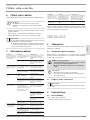 43
43
-
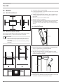 44
44
-
 45
45
-
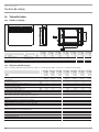 46
46
-
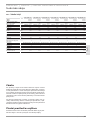 47
47
-
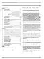 48
48
-
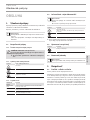 49
49
-
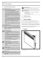 50
50
-
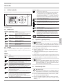 51
51
-
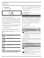 52
52
-
 53
53
-
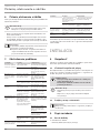 54
54
-
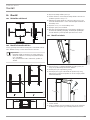 55
55
-
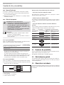 56
56
-
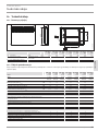 57
57
-
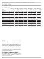 58
58
-
 59
59
-
 60
60
-
 61
61
-
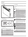 62
62
-
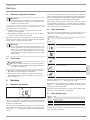 63
63
-
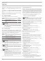 64
64
-
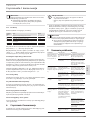 65
65
-
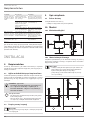 66
66
-
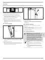 67
67
-
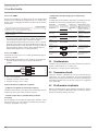 68
68
-
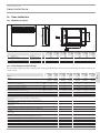 69
69
-
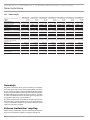 70
70
-
 71
71
-
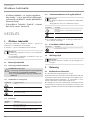 72
72
-
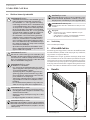 73
73
-
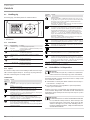 74
74
-
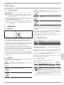 75
75
-
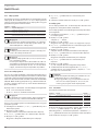 76
76
-
 77
77
-
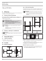 78
78
-
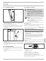 79
79
-
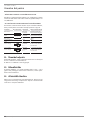 80
80
-
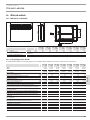 81
81
-
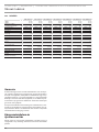 82
82
-
 83
83
-
 84
84
-
 85
85
-
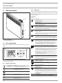 86
86
-
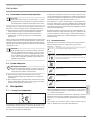 87
87
-
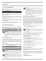 88
88
-
 89
89
-
 90
90
-
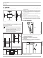 91
91
-
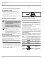 92
92
-
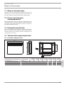 93
93
-
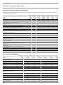 94
94
-
 95
95
-
 96
96


STIEBEL ELTRON CWM 500-3000 P | CWM 500-3000 U Operation Instruction
- Taper
- Operation Instruction
dans d''autres langues
Documents connexes
-
STIEBEL ELTRON CON 100-300 Manuel utilisateur
-
STIEBEL ELTRON CON 5 Premium Operation Instruction
-
-
-
-
-
-
-
-
